Article

Numerical Simulation of Cutting Performance of Coated Tools for Nickel-Based Superalloys

School of Mechanical and Materials Engineering, North China University of Technology, Beijing 100043, China
*
Author to whom correspondence should be addressed.
Coatings 2025, 15(11), 1275; https://doi.org/10.3390/coatings15111275
Submission received: 17 September 2025 / Revised: 10 October 2025 / Accepted: 28 October 2025 / Published: 3 November 2025
(This article belongs to the Section Surface Characterization, Deposition and Modification)

Abstract

During the machining of nickel-based superalloys using coated tools, a significant amount of cutting heat is generated. This study employs ABAQUS finite element analysis software to establish two-dimensional orthogonal cutting simulation models for three types of coated tools: single-layer AlTiN, double-layer AlTiN/AlCrN, and AlCrN/AlTiN. The research focuses on simulating the cutting temperature and cutting stress of carbide tools with these three different coating types and thicknesses when machining nickel-based superalloy GH4169. The simulation results indicate that the double-layer AlCrN/AlTiN-coated tool exhibits lower maximum cutting temperature and cutting stress on the tool rake face and tool substrate during the cutting process. Compared to the other two coated tools, the cutting temperature and cutting stress on the rake face are reduced by up to 13.2% and 13.3%, respectively. When the AlCrN/AlTiN coating thickness is 2.5 μm with a ratio of 1.5:1, the maximum cutting temperature and cutting stress are minimized. During the cutting process with coated tools, the cutting speed, coating type, and coating thickness significantly influence the maximum cutting temperature and cutting stress. Therefore, investigating the effects of cutting speed, coating type, and coating thickness on carbide-coated tools can reduce tool wear, extend tool life, and thereby improve machining efficiency.

1. Introduction

Nickel-based superalloys, as a class of outstanding heat-resistant special materials, can maintain stable performance under extreme working conditions ranging from 600 to 1100 °C. They not only resist corrosion from oxidizing media but also withstand complex stress loads. Currently, they have become the core material for manufacturing hot-section components of aero-engines, such as turbine blades and combustion chambers [1]. Due to its unique alloy composition, the GH4169 nickel-based superalloy exhibits excellent fatigue, oxidation, radiation, creep, and corrosion resistance. It not only demonstrates high strength but also maintains outstanding performance during machining [2], meaning that it is widely used in the manufacturing of various components for aerospace engines. However, despite its exceptional performance in application, GH4169 is often considered a difficult-to-machine material due to its low thermal conductivity, low elastic modulus, high strength, and high chemical reactivity. Specifically, during the cutting process, challenges such as high cutting forces, elevated cutting temperatures, and significant tool wear are prominent. With the increasing demands of modern high-speed machining on tool performance, traditional materials like carbide and high-speed steel are increasingly inadequate to meet the evolving requirements. Tool coating technology, as a key method to enhance tool performance, serves as an ideal wear-resistant, protective layer on the tool surface. It not only offers high hardness, low friction, wear resistance, high-temperature resistance, and oxidation resistance but also significantly extends the service life of carbide cutting tools. As a result, it has found extensive application in modern machining processes [3].
Currently, extensive research has been conducted both domestically and internationally on the high-speed machining of nickel-based superalloy GH4169. With the advancement of simulation software technology, finite element simulation has been widely applied in the field of carbide tool machining. Song Xinhua et al. [4] conducted simulation experiments using DEFORM-3D v6.1 software and concluded that cutting speed has the most significant impact on cutting temperature. Other scholars have utilized finite element simulation to investigate changes in cutting temperature, cutting stress, and chip formation mechanisms during machining processes [5]. Lu Tao et al. [6] simulated high-speed milling of Ti6Al4V titanium alloy, analyzing the distribution of and variation in stress, strain, temperature field, and cutting forces on both the tool and workpiece during machining. Gao Dongqiang et al. [7] performed cutting simulations on nickel-based superalloys to study the influence of different tool rake angles on chip morphology and cutting force patterns. They found that when the tool rake angle ranges from 3° to 5°, the chip morphology remains continuous, and cutting forces are relatively low. Sun Huilai et al. [8] conducted both two-dimensional cutting simulations and experimental tests on 7050 aluminum alloy, obtaining simulated and experimental values of cutting force, cutting temperature, stress, and strain during the machining process. The results demonstrated that the simulation values align well with theoretical values from actual machining. Wang Zhe et al. [9] simulated cutting forces and temperatures during turning of Inconel 718 nickel-based superalloy, revealing that cutting speed has the greatest impact on cutting temperature, while depth of cut most significantly affects cutting force. Lü Na [10] conducted a finite element simulation study on carbide tool wear, and the numerical results from experiments and simulations were largely consistent, validating the accuracy and feasibility of finite element cutting simulation technology. Grzesik et al. [11] investigated the heat generation and temperature distribution between coated tools and chips during machining using tools with different coating types through finite element simulation technology. Sadeghifar et al. [12] studied the influence of tool geometry factors and cutting parameters on surface residual stress, cutting force, and cutting temperature during the machining of 300 M steel with carbide tools. They employed a multi-objective optimization method to systematically analyze the coupling relationship between process parameters (such as cutting speed and feed rate) and geometric factors (such as tool rake angle and edge bluntness), achieving global optimization of parameter combinations under multiple constraints. This approach provides a solution combining theoretical rigor and engineering applicability for high-precision machining of nickel-based superalloy GH4169. Qin et al. [13] investigated the effect of coating thickness on diamond-coated tools. Using the finite element method, they simulated the influence of coating thickness on residual stress and quantitatively calculated its impact on the interfacial stress of the tools. The study revealed that coating thickness increases residual stress at the coating–substrate interface, thereby enhancing the coating’s crack resistance and delamination resistance. Kumar et al. [14] studied the influence of thickness and the microstructure of nitride coatings such as AlCrN and AlTiN on machining performance. The study found that thinner coatings (<2 μm) are prone to coating peeling, while thicker coatings (>3 μm) may lead to crack propagation due to residual stress accumulation. For AlTiN-coated tools, the adhesion of the coating to the substrate increases with thickness, whereas for AlCrN coatings, a 3 μm coating exhibited the best substrate adhesion. Wang et al. [15] used finite element analysis to construct a coupled model of coating and ceramic substrate, considering the thermophysical parameters and interfacial bonding characteristics of coating materials (e.g., Al2O3, TiAlN) and ceramic substrates (e.g., Al2O3/TiCN).
The use of finite element simulation software for simulating metal cutting processes enables the quick and accurate prediction of the values and distribution of maximum cutting stress and peak cutting temperature on both the tool and workpiece during actual machining. Based on this, this study employs numerical simulation technology, leveraging the high hardness and excellent high-temperature oxidation resistance of AlCrN coatings, as well as the strong adhesion of AlTiN coatings to carbide tool substrates. Using Abaqus CAE2020 finite element simulation software, a two-dimensional orthogonal cutting finite element model was established for the nickel-based superalloy GH4169. The cutting stress and cutting temperature of three coating tool materials—single-layer AlTiN, double-layer AlTiN/AlCrN, and AlCrN/AlTiN—were analyzed under different cutting speeds. The findings provide valuable insights for practical machining processes and can serve as a reference for the development of high-speed cutting simulation models.

2. Establish a Two-Dimensional Cutting Finite Element Model

2.1. Constitutive Models for Superalloys and Physical Parameters of Coating Materials

During the actual cutting process, significant cutting heat is generated due to friction between the tool and the workpiece. As a result, the GH4169 nickel-based superalloy often undergoes elastoplastic strain. When selecting a constitutive model for the material, the influence of strain on the workpiece during machining should be considered. The classical Johnson–Cook (J-C) constitutive model can describe the strain hardening and thermal softening behaviors of materials under high strain rate conditions [16]. It is generally applicable to the failure analysis of metals under large strain, high strain rates, and elevated temperatures. This model is derived from extensive stress–strain data simulations. Therefore, the J-C constitutive relation model is selected, and its expression [17] is as follows:
δ = A + B ε n [ 1 + C ln ( ε ˙ ε ˙ 0 ) ] [ 1 ( T T 0 T m e l t T 0 ) m ]
In the formula δ represents the equivalent plastic stress; A, B, C, m, and n are the relevant parameters of the constitutive equation; ε is the equivalent plastic strain; ε ˙ is the equivalent plastic strain rate; ε ˙ 0 is the reference strain rate; Tmelt is the melting temperature of the material; and T0 is the initial temperature (taken as 20 °C). The first term of the expression represents the strain hardening effect of the material, the second term represents the strain rate hardening effect, and the third term represents the thermal softening effect. The parameters of the constitutive model equation for the GH4169 nickel-based superalloy material [18] are listed in Table 1.
The simulation utilized experimental data from the relevant literature, and the specific physical parameters of the tool coating materials employed [19] are shown in Table 2.

2.2. Material Damage and Chip Separation Criterion

To better align with the actual conditions of the machining process, this study adopts a physical chip separation criterion, which determines whether chip separation occurs based on whether relevant physical quantities reach a threshold value. The Johnson–Cook (J-C) damage evolution model is a cumulative damage model whose key parameters encompass strain rate, thermal softening, and strain hardening. It is also an instantaneous failure model, where each element integration point fails once the damage parameter reaches a certain value. This model effectively reflects the damage behavior of metallic materials. Its failure parameter model is expressed as follows:
w = j = 1 n ε p l ¯ ε f p l ¯
In the formula,   w   represents the ratio of the equivalent plastic strain at the element integration point to the critical equivalent plastic strain. When the damage parameter w > 1 , fracture occurs in the workpiece material, resulting in a complete loss of stiffness in the localized material. The corresponding element mesh is deleted, and the chip gradually forms; ε p l ¯ denotes the increment of equivalent plastic strain rate and  ε f p l ¯ represents the equivalent plastic strain at material failure. The parameters of the failure model for the GH4169 nickel-based superalloy [20] are listed in Table 3.

2.3. Finite Element Model

A two-dimensional cutting simulation experiment was conducted using the ABAQUS finite element simulation software. Figure 1 illustrates the constructed orthogonal cutting finite element model. The geometric dimensions of the workpiece were set to a length of 1.3 mm and a width of 0.3 mm, and it was defined as a deformable body. Mesh generation is crucial for the efficiency and accuracy of finite element simulations. Selecting appropriate mesh types and quantities while ensuring reasonable mesh distribution not only guarantees the accuracy of finite element analysis but also improves computational efficiency. To enhance both model runtime efficiency and simulation precision, the workpiece model was divided into two regions: the cutting zone and the non-cutting zone. The non-cutting zone utilized rectangular elements, while the cutting zone employed square elements with localized refinement. The geometric dimensions of the tool model were as follows: tool tip length of 0.30 mm, tool height of 0.35 mm, tool rake angle of 5°, tool relief angle of 5°, and tool tip radius of 0.02 mm. The three coating materials applied to the tool surface were all set to a thickness of 3 μm. The workpiece was meshed using a structured grid, while the tool was meshed using a free grid. Both the tool and workpiece employed CPE4RT element types. To prevent distortion during the cutting simulation, a rigid body constraint was applied to the tool relative to the reference point RF. A cutting speed along the X-axis was imposed at this point to achieve transverse cutting. Node P is the boundary point between the coating and the tool substrate on the rake face. This point was designated to output the cutting temperature and cutting stress of the tool substrate during post-processing analysis.

3. Cutting Simulation Results and Analysis

3.1. Effect of Coating Types on Cutting Temperature of Tools

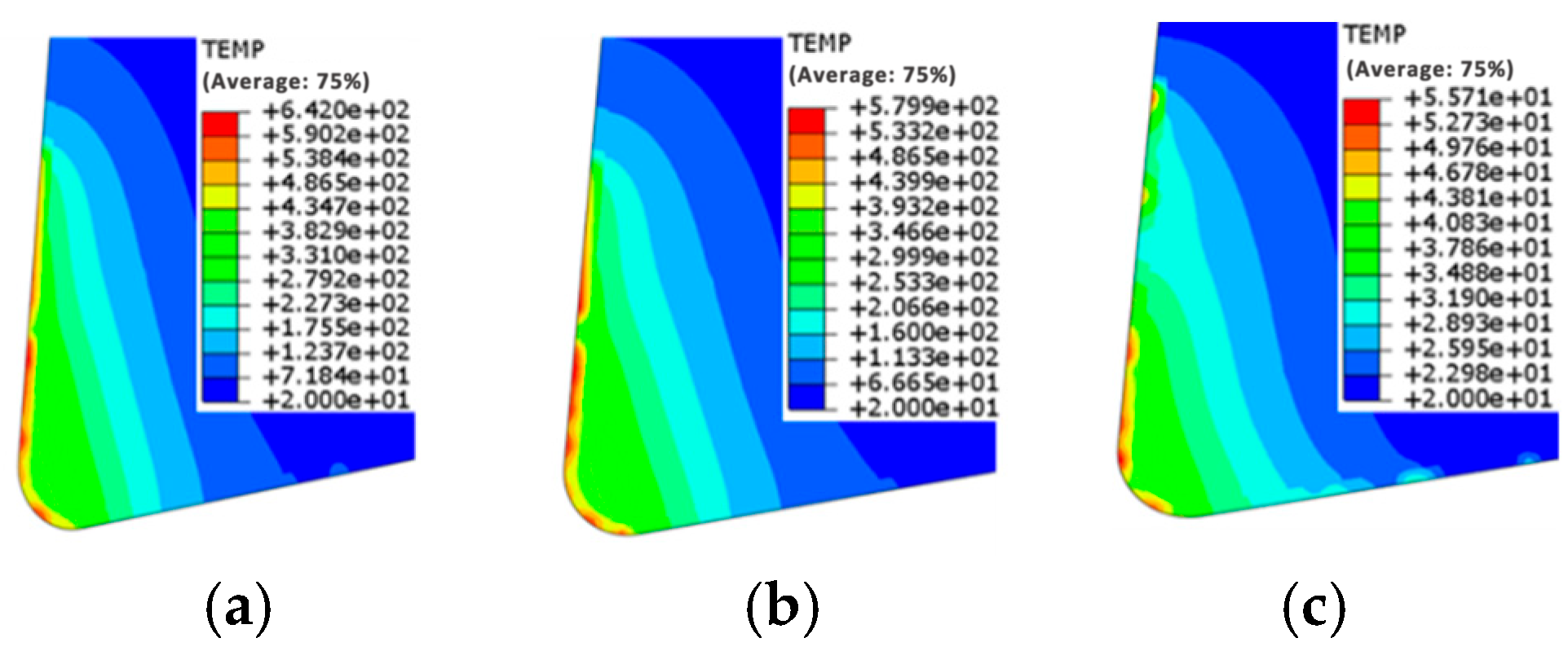
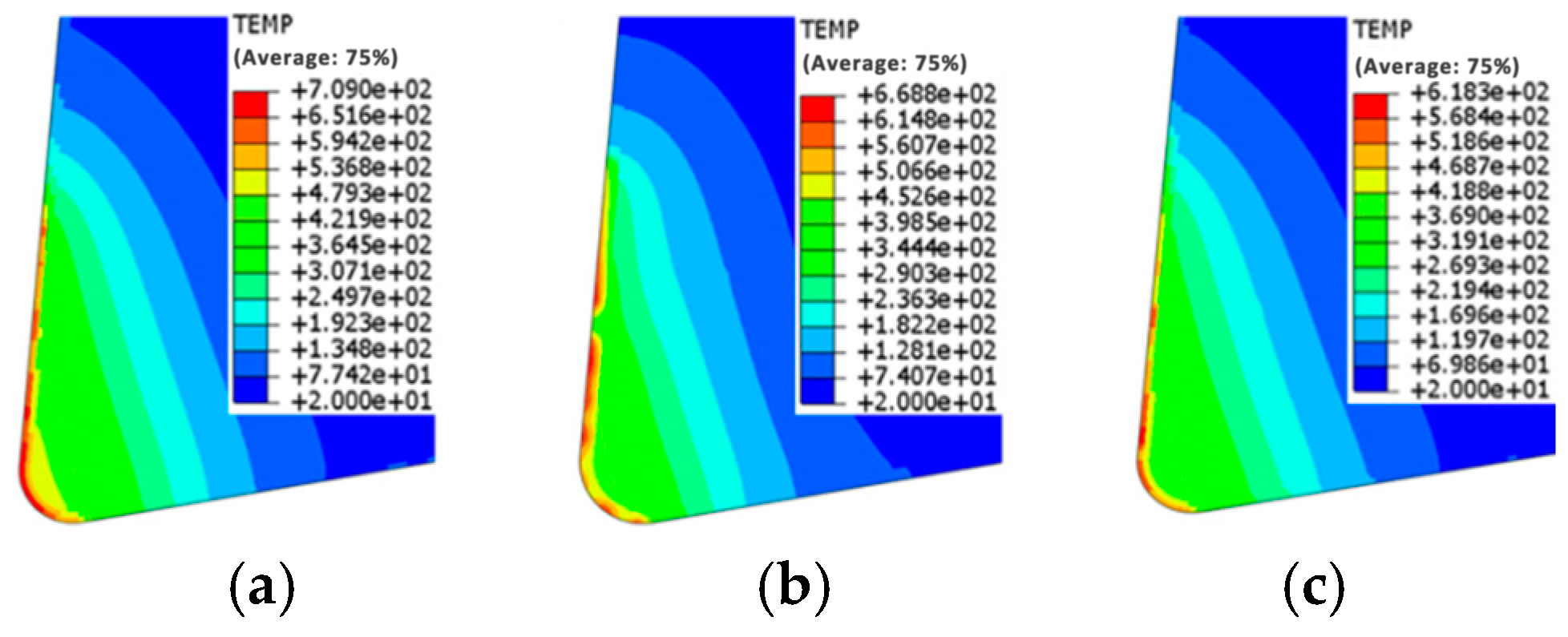
Figure 2, Figure 3 and Figure 4 present the distribution of maximum cutting temperature on the rake face of three types of coated tools at cutting speeds ranging from 60 to 180 m/min.
From Figure 2, Figure 3 and Figure 4, the distribution of the maximum cutting temperature on the rake face of the three types of coated tools can be clearly observed. Based on the temperature contour maps of the rake face for these three coated tools, it is possible to not only determine the peak temperature and its location on the rake face but also to observe that the temperature gradient in the region of the rake face in contact with the chip is very steep. According to the temperature contour maps, when the cutting speed increases from 60 m/min to 180 m/min, the maximum cutting temperature on the rake face of the double-layer AlCrN/AlTiN-coated tool decreases by approximately 13.2% compared to that of the single-layer AlTiN-coated tool and by about 7.6% compared to that of the double-layer AlTiN/AlCrN-coated tool. Additionally, the area of the high-temperature region on the rake face of the double-layer AlCrN/AlTiN-coated tool is the smallest. Therefore, the double-layer coated tool significantly reduces the cutting temperature during the machining process. Under different cutting speeds ranging from 60 to 180 m/min, the three tool coating materials exhibit significant differences in their influence on the temperature of the tool rake face. As the cutting speed increases, the maximum temperature on the rake face rises considerably for all three coating materials. This is because higher cutting speeds result in faster chip flow, increased material removal per unit time, and greater power consumption during cutting. Simultaneously, intense friction between the chip and the coated tool rake face generates a substantial amount of heat. On the other hand, the increased cutting speed causes the heat generated by friction to accumulate rapidly, leaving insufficient time for it to dissipate into the chip interior. As a result, the chip cannot carry away the excessive cutting heat in time, leading to a rise in the temperature of the tool rake face. Furthermore, the temperature contour maps of the tool rake face indicate that as the cutting speed increases, the high-temperature region on the rake face gradually shifts away from the tooltip arc area and moves toward the rake face. This shift is related to the decrease in chip sliding velocity at lower cutting speeds. However, excessively high rake face temperatures can promote adhesion between the workpiece material and the tool, as well as cause softening of the tool surface material, accelerating tool wear and failure. This phenomenon primarily manifests as crater wear on the rake face of the coated tool.
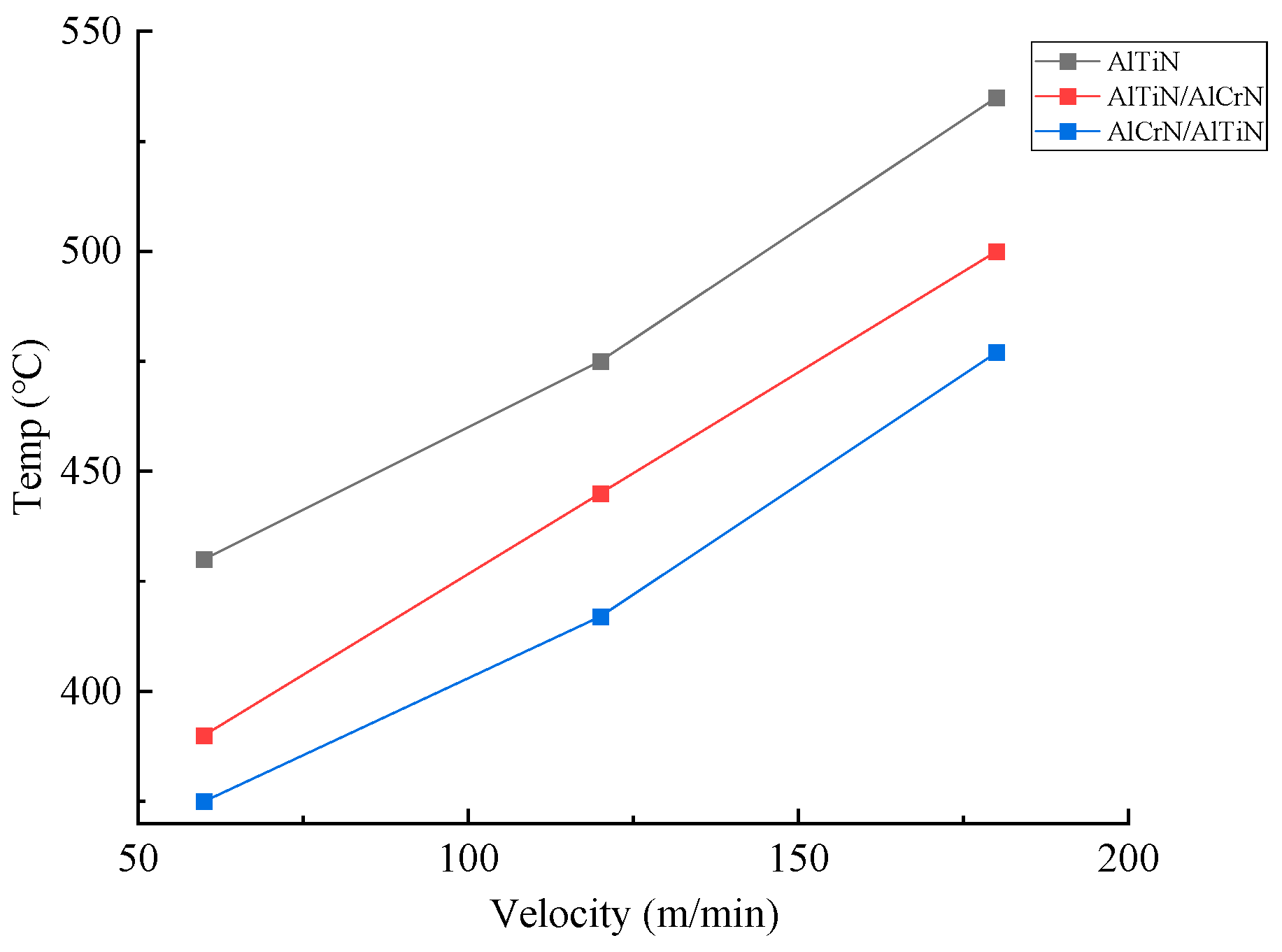
To further understand the variations in the substrate temperature of different coated tools during the cutting process, a line chart of the maximum substrate temperature for the three types of coated tools under different cutting speeds is plotted, as shown in Figure 5. Compared to the AlTiN- and AlTiN/AlCrN-coated tools, the AlCrN/AlTiN-coated tool exhibits lower temperatures on both the rake face and the tool substrate during cutting. This is primarily because the AlCrN/AlTiN composite coating, on the one hand, features an interlayer structure that acts as a thermal barrier and buffer. The presence of such a temperature gradient allows each layer to bear different thermal loads. On the other hand, the outer AlCrN layer of the composite coating has a lower coefficient of friction, which reduces friction between the tool rake face and the chip. This decrease in frictional work at the rake face–workpiece interface minimizes heat transfer to the tool substrate, resulting in less heat generation during tool–workpiece cutting compared to AlTiN- and AlTiN/AlCrN-coated tools. Moreover, when AlCrN serves as the outer layer, its strong oxidation resistance and low thermal conductivity create a thermal barrier that further reduces heat transfer into the tool interior and substrate, thereby providing better protection for the tool substrate material.

3.2. Effect of Coating Types on Cutting Stress of Tools

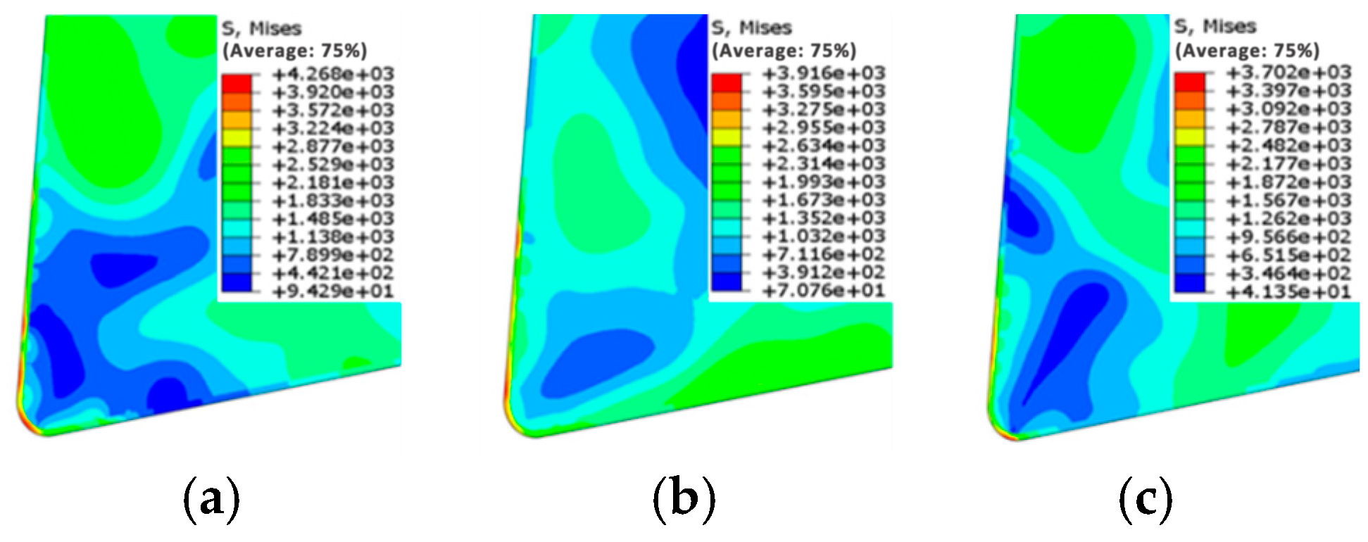
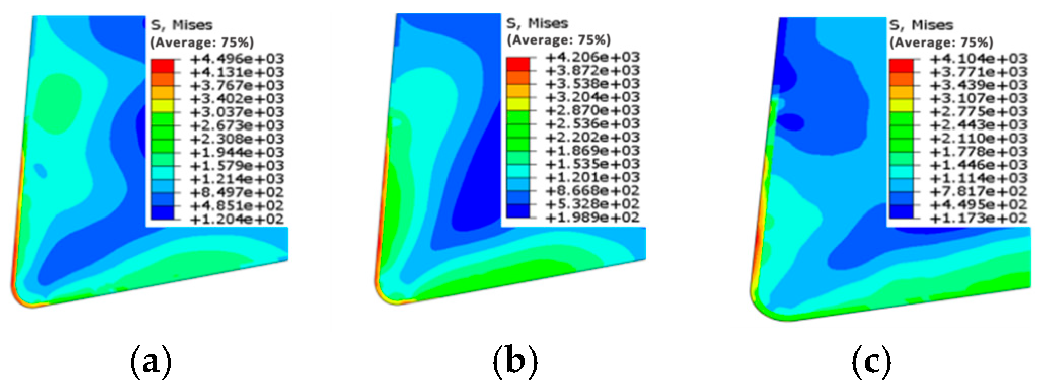
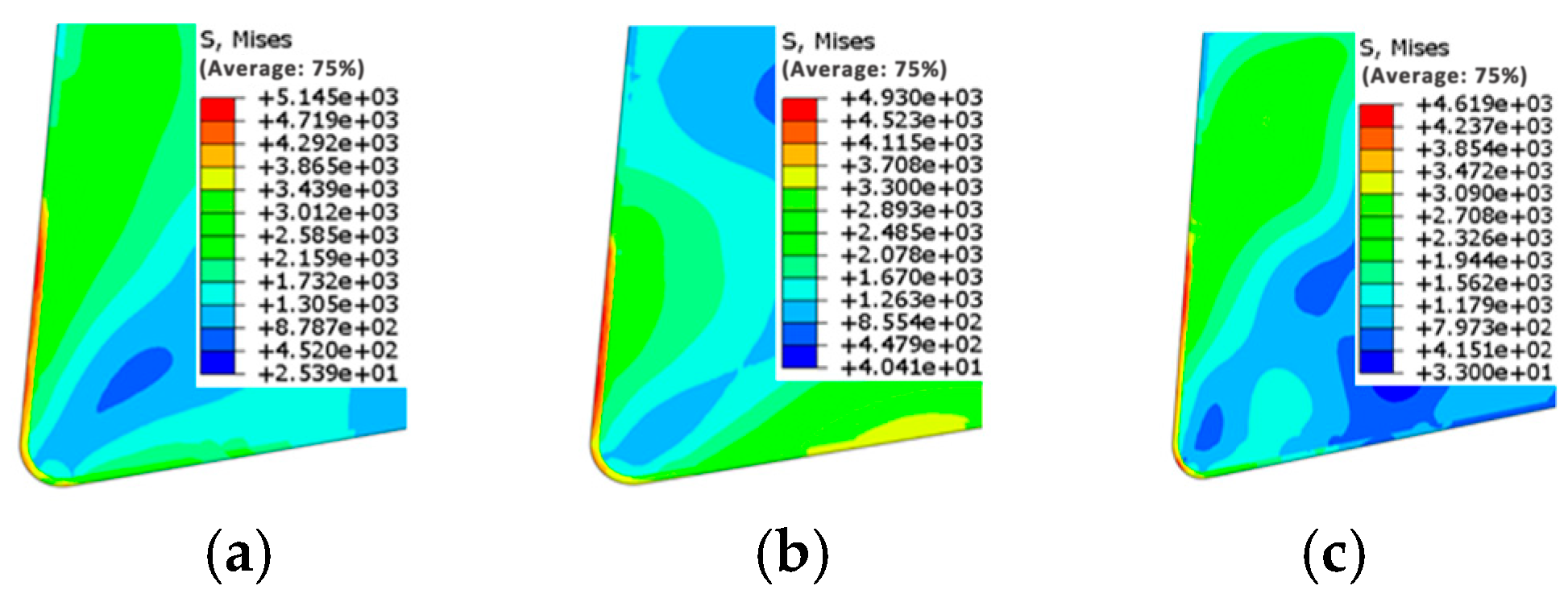
Figure 6, Figure 7 and Figure 8 illustrate the distribution of maximum cutting stress on the rake face of three types of coated tools at cutting speeds ranging from 60 to 180 m/min.
The maximum cutting stress generated during the tool cutting process and its distribution can reflect the wear condition and location of coated tools, thereby significantly affecting their service life. The maximum cutting stress values and their distribution on the rake face of the three types of coated tools under different cutting speeds are shown in Figure 6, Figure 7 and Figure 8. As the cutting speed increased, the maximum cutting stress on the rake face of all three coated tools continuously rose. When the speed increased from 120 m/min to 180 m/min, a significant increase in the maximum cutting stress was observed for the AlTiN-coated and AlTiN/AlCrN-coated tools. In contrast, when the speed increased from 60 m/min to 120 m/min, the stress increase for these two tools was relatively modest. The AlCrN/AlTiN-coated tool exhibited the smallest increase in stress values compared to the other two coated tools. When the cutting speed was raised from 60 m/min to 180 m/min, the maximum stress on the rake face of the AlCrN/AlTiN-coated tool was reduced by approximately 13.3% compared to the single-layer AlTiN-coated tool and by about 6.3% compared to the AlTiN/AlCrN-coated tool. Therefore, based on the changes observed in the simulation contour maps, it can be concluded that the double-layer AlCrN/AlTiN-coated tool significantly reduces cutting stress and minimizes tool wear during the machining process.
To further investigate the variation in the maximum cutting stress values of the substrate for the three types of coated tools, a line chart illustrating the maximum stress experienced by the tool substrate under different cutting speeds is plotted, as shown in Figure 9. Combined with the contour maps of the maximum stress on the rake face of the coated tools, it is observed that the trend of the maximum stress on the tool substrate with increasing cutting speed is generally consistent with that on the rake face. This phenomenon may be attributed to the enhanced friction and extrusion effects between the coated tool and the workpiece material as the cutting speed increases. However, the multilayer structure of the composite coating disperses thermal loads through the synergistic action of each layer, reduces interfacial thermal stress, and minimizes stress concentration, thereby significantly lowering the tool wear rate, substantially extending tool life, and stabilizing cutting stress. Additionally, the outer AlCrN layer of the AlCrN/AlTiN composite coated tool exhibits excellent high-temperature stability, high-temperature red hardness, and a low coefficient of friction, which reduces cutting heat and tool–workpiece adhesive wear, consequently lowering cutting stress. It is noteworthy that the high-stress area on the coated tool at 180 m/min shows a slight shift from the tooltip toward the rake face. This indicates severe wear near this location on the coated tool, suggesting that the stress distribution in coated tools can predict the primary wear regions of cutting tools.

3.3. Effect of Coating Thickness Ratio on Cutting Temperature of Tools

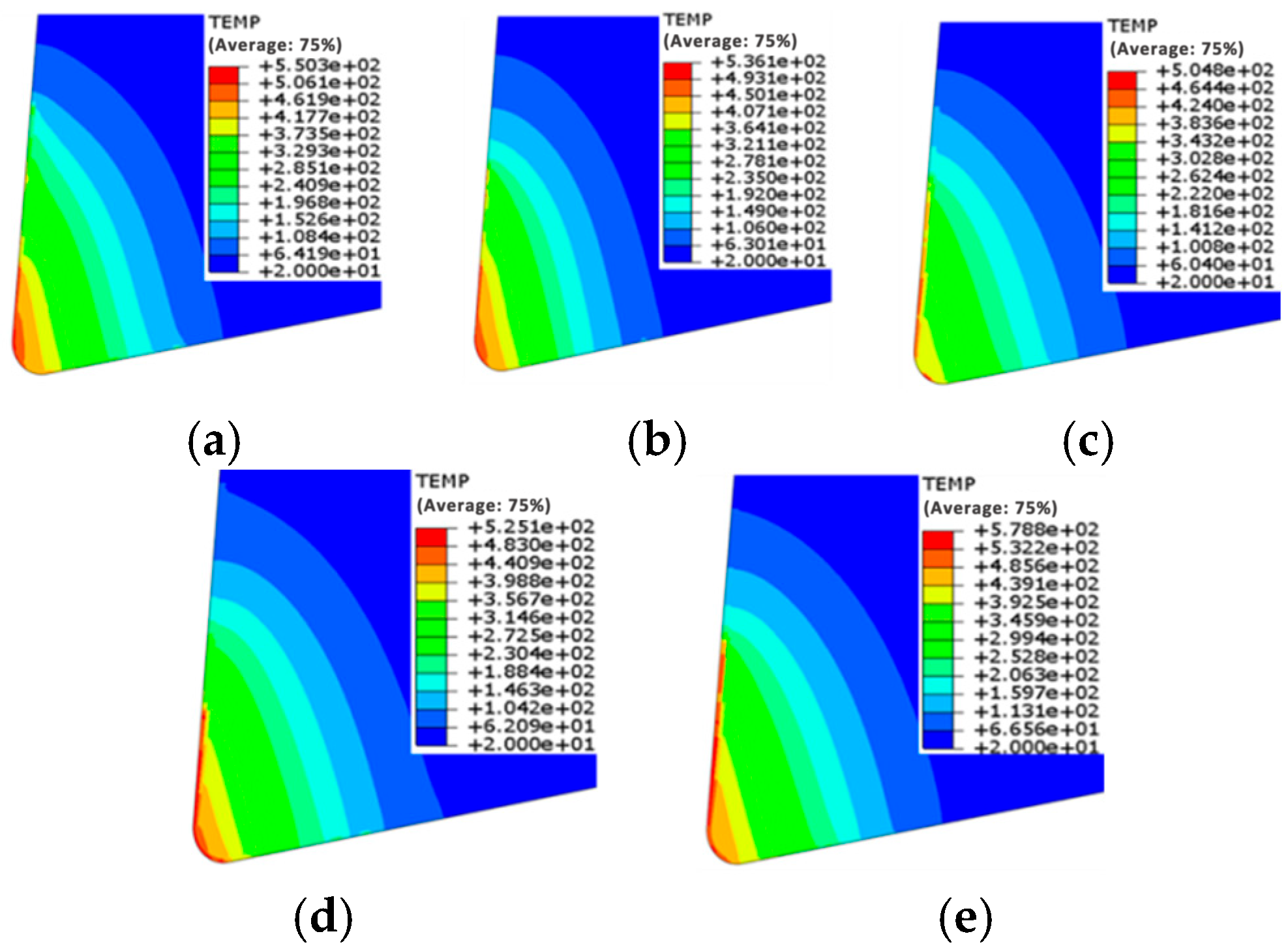
Figure 10 displays the distribution of the maximum cutting temperature on the rake face of double-layer AlCrN/AlTiN-coated tools with different thickness ratios at a cutting speed of 60 m/min.
Figure 10 shows the variation in contour maps of the maximum cutting temperature under five different coating thickness ratios. It can be observed that as the thickness of the AlCrN coating increases, the maximum temperature on the rake face of the double-layer AlCrN/AlTiN-coated tool first decreases and then increases. When the coating thickness ratio is 1.5:1, the maximum cutting temperature on the rake face of the coated tool is the lowest. At this point, the highest temperature point on the rake face is located closer to the tool tip. The simulation results indicate that an appropriate AlCrN coating thickness contributes more effectively to improving the cutting performance of the tool.

3.4. Effect of Coating Thickness on Cutting Stress of Tools

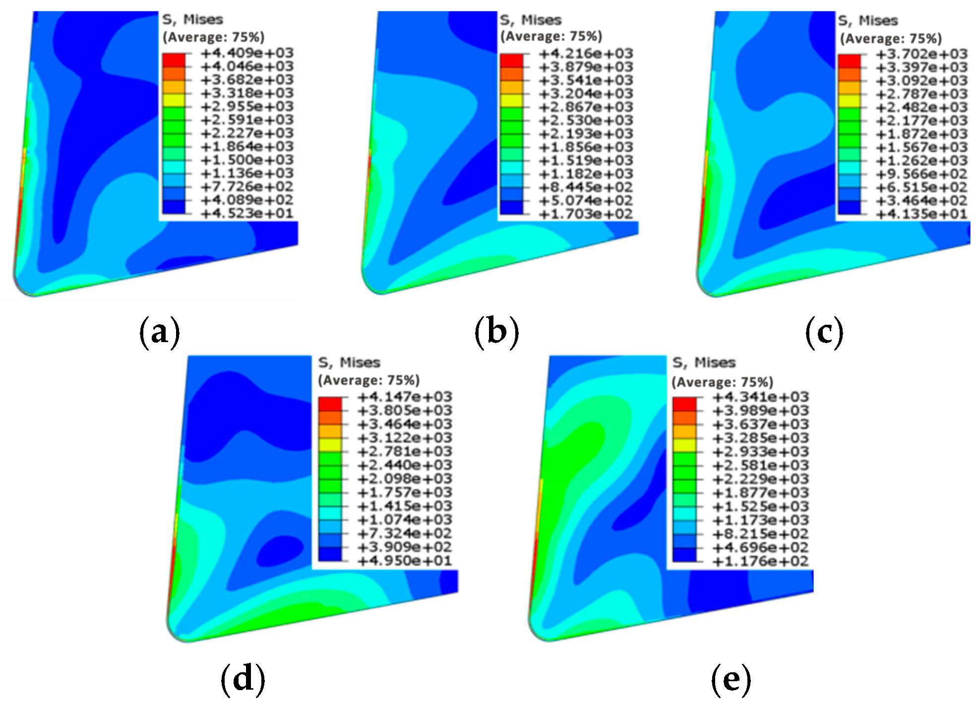
Figure 11 shows the variation in contour maps of the maximum cutting stress under five different coating thicknesses. It can be observed that when the coating thickness ranges from 1.5 μm to 2.5 μm, the maximum stress decreases with increasing coating thickness. However, when the coating thickness increases from 2.5 μm to 3.5 μm, the maximum stress exhibits an upward trend. The lowest maximum stress value on the rake face of the coated tool occurs at a coating thickness of 2.5 μm.

4. Conclusions

This study utilized Abaqus CAE2020 simulation software to establish a finite element model of coated tools machining nickel-based superalloy GH4169, systematically analyzing the cutting performance of single-layer AlTiN coating, double-layer AlTiN/AlCrN coating, and double-layer AlCrN/AlTiN coating. The research simulated the process of machining GH4169 superalloy using these three types of coated tools, investigating the effects of cutting speed, coating type, and coating thickness on the cutting performance of the tools from the perspectives of maximum cutting temperature and maximum cutting stress. Furthermore, the influence of different coating materials on the temperature and stress of the tool substrate under varying cutting speeds was analyzed. The simulation results are summarized as follows:
(1)
During the cutting process, the maximum cutting temperature and maximum cutting stress experienced by the three types of coated tools are primarily distributed at the tooltip and on the rake face. As the cutting speed increases, both the maximum temperature and maximum stress of the three coated tools show a significant upward trend. Additionally, the high-temperature and high-stress areas exhibit a slight shift from the tooltip toward the rake face. It can be predicted that the wear region of the coated tools will primarily manifest as crater wear on the rake face.
(2)
The double-layer AlCrN/AlTiN-coated tool exhibits the lowest maximum cutting temperature and cutting stress on both its rake face and tool substrate during machining compared to the other two types of coated tools (AlTiN and AlTiN/AlCrN).
(3)
When the AlCrN/AlTiN coating thickness ratio is 1.5:1 with a total thickness of 2.5 μm, the minimum values of maximum cutting temperature and maximum cutting stress are achieved, indicating the optimal cutting performance of the coated tool.

Author Contributions

Conceptualization, Z.D. and L.Z.; methodology, Z.D. and L.Z.; validation, Z.D.; writing—original draft preparation, Z.D. and L.Z.; writing—review and editing, all authors; supervision, Z.D. All authors have read and agreed to the published version of the manuscript.

Funding

This research was funded by [Special Project for the Construction of an Organized Research Quality Management System] grant Number [110051360024XN148-38].

Institutional Review Board Statement

Not applicable.

Informed Consent Statement

Not applicable.

Data Availability Statement

The raw data supporting the conclusions of this article will be made available by the corresponding authors upon request.

Acknowledgments

The research was supported by all authors.

Conflicts of Interest

The authors declare no conflicts of interest.

References

  1. Fu, Q.F.; Yang, X.L.; Liu, K.M. Current Status of Research and Prospect of High Temperature Materials for Aeroengine. Heat Treat. Technol. Equip. 2018, 39, 69–73. [Google Scholar]
  2. Xu, X.W.; Li, L.C.; Wu, A.J.; Chen, C.; Cui, J.B.; Xiong, J.; Liu, J.B. Research on Cutting Performance of High Performance Coated Tools for Cutting GH4169 High Temperature Alloy. Tool Eng. 2024. [Google Scholar]
  3. Zhang, E.G.; Zhu, Z.; Zhang, T.B. Research Progress and Application of Superhard Nano-Micron PVD Coating Technology in the Cutting Manufacturing Area. Surf. Technol. 2015, 44, 89–96+108. [Google Scholar]
  4. Song, X.H.; Gao, H.W.; Tian, Z.F.; Song, B. Numerical Simulation of Titanium Alloy Ti6Al4V in Cutting Proce. Tool Eng. 2020, 54, 40–43. [Google Scholar]
  5. Zhang, S.; Li, B.X.; Li, Q.H.; Man, J. Advances in Finite Element Simulation of the Cutting Process. Aeronaut. Manuf. Technol. 2019, 62, 14–28. [Google Scholar]
  6. Lu, T.; Xiang, G.Q.; Zhang, J.D. Analysis and Simulation of High—Speed Milling of Titanium Alloy Ti6Al4V. Modul. Mach. Tool Autom. Manuf. Tech. 2015, 149–151+160. [Google Scholar]
  7. Gao, D.Q.; Wang, J.J.; Wang, X.Y. Study on Cutting Process and Tool Parameter Finite Element Simulation of Nickel based Superalloy. Tool Eng. 2017, 51, 80–83. [Google Scholar]
  8. Sun, H.L.; Li, D.; Zhao, F.F.; Yu, X.X. Two-dimensional simulation on cutting process of aviation 7075 aluminum alloy based on ABAQUS. J. Tianjin Polytech. Univ. 2017, 36, 83–88. [Google Scholar]
  9. Wang, Z.; Li, L.; Shen, X.H. Analysis of Cutting Force and Cutting Temperature of Nickel-based Superalloy Inconel 718 Based on Grey Relational Analysis. Tool Eng. 2019, 53, 51–54. [Google Scholar]
  10. Lv, N. Research on Wear Mechanism of Cemented Carbide Tool Based on ABAQUS Finite Element Simulation. Mach. Tool Hydraul. 2021, 49, 164–168. [Google Scholar]
  11. Grzesik, W.; Bartoszuk, M.; Nieslony, P. Finite element modelling of temperature distribution in the cutting zone in turning processes with differently coated tools. J. Mater. Process. Technol. 2005, 164–165, 1204–1211. [Google Scholar] [CrossRef]
  12. Sadeghifar, M.; Sedaghati, R.; Jomaa, W. Finite element analysis and response surface method for robust multi performance optimization of radial turning of hard 300 M steel. Int. J. Adv. Manuf. Technol. 2018, 94, 2457–2474. [Google Scholar] [CrossRef]
  13. Qin, F.; Chou, Y.; Nolen, D. Coating thickness effects on diamond coated cutting tools. Surf. Coat. Technol. 2009, 204, 1056–1060. [Google Scholar] [CrossRef]
  14. Kumar, S.C.; Patel, K.S. Investigations on the effect of thickness and structure of AlCr and AlTi based nitride coatings during hard machining process. J. Manuf. Process. 2018, 31, 336–347. [Google Scholar] [CrossRef]
  15. Wang, H.; Zhang, J.; Yi, M. Simulation study on influence of coating thickness on cutting performance of coated ceramic cutting tools. J. Phys. Conf. Ser. 2020, 1549, 032140. [Google Scholar] [CrossRef]
  16. Zhang, Y.; Mabrouki, T.; Nelias, D. Chip formation in orthogonal cutting considering interface limiting shear stress and damage evolution based on fracture energy approach. Finite Elem. Anal. Des. 2011, 47, 850–863. [Google Scholar] [CrossRef]
  17. He, Y.; Xu, Z.C.; Li, P.; Liu, M.; Gao, X.J.; Fan, L. Simulation Study on Cutting Titanium Alloy with Micro-Texture Tool Based on ABAQUS. J. Liaoning Petrochem. Univ. 2024, 44, 61–69. [Google Scholar]
  18. Kobayashi, T.; Simons, J.W.; Brown, C.S.; Shockey, D.A. Plastic flow behavior of Inconel 718 under dynamic shear loads. Int. J. Impact Eng. 2008, 35, 389–396. [Google Scholar] [CrossRef]
  19. Zhang, H.D.; Zhang, L.; Chen, Y.; Luo, G.K.; Xiao, Q.P.; Zhong, Z.Q. Failure modes of AlTiN coated alloys during scratch test and the related mechanism by finite element analysis. Powder Metall. Mater. Sci. Eng. 2018, 23, 445–453. [Google Scholar] [CrossRef] [PubMed]
  20. Bu, J.A.; Huang, S.T.; Yu, X.L.; Xu, L.F. Simulation of Residual Deformation and Cutting Force in High Speed Cutting of GH4169 Nickel-Based Superalloy. J. Aerosp. Mater. Technol. 2019, 49, 27–34. [Google Scholar]
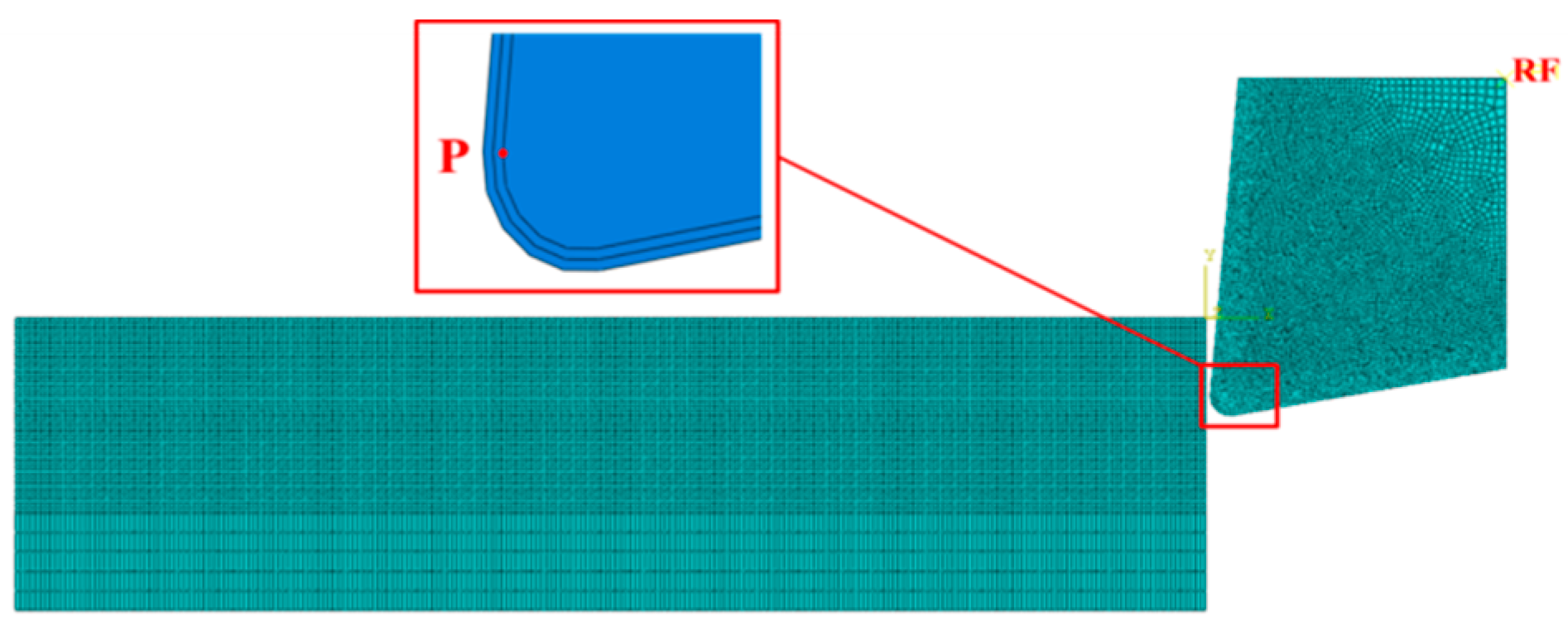
Figure 1. Finite element model of orthogonal cutting.
Coatings 15 01275 g001
Figure 2. Maximum temperature distribution of tools: (a) AlTiN coating; (b) AlTiN/AlCrN coating; (c) AlCrN/AlTiN coating. Cutting conditions: cutting speed v = 60 m/min; feed rate f = 0.1 mm/rev.
Coatings 15 01275 g002
Figure 3. Maximum temperature distribution of tools: (a) AlTiN coating; (b) AlTiN/AlCrN coating; (c) AlCrN/AlTiN coating. Cutting conditions: cutting speed v = 120 m/min; feed rate f = 0.1 mm/rev.
Coatings 15 01275 g003
Figure 4. Maximum temperature distribution of tools: (a) AlTiN coating; (b) AlTiN/AlCrN coating; (c) AlCrN/AlTiN coating. Cutting conditions: cutting speed v = 180 m/min; feed rate f = 0.1 mm/rev.
Coatings 15 01275 g004
Figure 5. Maximum temperature of substrate in the rake face of coated tools at different cutting speeds.
Coatings 15 01275 g005
Figure 6. Maximum stress distribution of tools: (a) AlTiN coating; (b) AlTiN/AlCrN coating; (c) AlCrN/AlTiN coating. Cutting conditions: cutting speed v = 60 m/min; feed rate f = 0.1 mm/rev.
Coatings 15 01275 g006
Figure 7. Maximum stress distribution of tools: (a) AlTiN coating; (b) AlTiN/AlCrN coating; (c) AlCrN/AlTiN coating. Cutting conditions: cutting speed v = 120 m/min; feed rate f = 0.1 mm/rev.
Coatings 15 01275 g007
Figure 8. Maximum stress distribution of tools: (a) AlTiN coating; (b) AlTiN/AlCrN coating; (c) AlCrN/AlTiN coating. Cutting conditions: cutting speed v = 180 m/min; feed rate f = 0.1 mm/rev.
Coatings 15 01275 g008
Figure 9. Maximum stress of substrate on the rake face of coated tools at different cutting speeds.
Coatings 15 01275 g009
Figure 10. Temperature distribution of tools: (a) 1:1; (b) 1.2:1; (c) 1.5:1; (d) 2:1; (e) 2.5:1. Cutting conditions: cutting speed v = 60 m/min; feed rate f = 0.1 mm/rev.
Coatings 15 01275 g010
Figure 11. Stress distribution of tools: (a) 1.5 μm; (b) 2.0 μm; (c) 2.5 μm; (d) 3.0 μm; (e) 3.5 μm. Cutting conditions: cutting speed v = 60 m/min; feed rate f = 0.1 mm/rev.
Coatings 15 01275 g011
Table 1. Constitutive model equation parameters of GH4169 nickel-based superalloy.
Yield Strength
A
Strain Hardening Coefficient
B
Strain Rate Hardening
Coefficient C
Strain Hardening Exponent
n
Coefficient of Thermal Softening m
9801370170.02 1.03
Table 2. Physical parameters of coating materials.
Coating TypeDensity t/mm3Elasticity Modulus MPaPoisson RateConduction w/m·°C
AlCrN4.8 × 10−9500,000 0.255
AlTiN2.1 × 10−9446,0000.216
Table 3. Failure parameters of GH4169 nickel-based superalloy.
d1d2d3d4d5
0.2390.456 −0.3 0.072.5
Disclaimer/Publisher’s Note: The statements, opinions and data contained in all publications are solely those of the individual author(s) and contributor(s) and not of MDPI and/or the editor(s). MDPI and/or the editor(s) disclaim responsibility for any injury to people or property resulting from any ideas, methods, instructions or products referred to in the content.