Abstract
This work presents a study on the fabrication of polymethyl methacrylate (PMMA) coatings on NiTi alloys using the spin-coating technique, combining numerical simulation with COMSOL Multiphysics 6.3 and experimental validation. This study provides a numerical framework and parametric study of a COMSOL-based simulation framework for estimating the PMMA coating thickness during the spin-coating process. We present an axisymmetric numerical framework, consistent with classical analytical trends; we provide parametric maps (viscosity, rpm, volume) to delimit thickness ranges (e.g., 100–300 μm). Limitations with no experimental validation are included and evaporation is not modeled; therefore, the figures are indicative estimates. The spin-coating parameters, such as the rotation speed, internal pressure, viscosity of the PMMA solution, and initial volume of the polymer solution, are considered important factors for the simulation process. The coating parameters determine the thickness of the coating layer achieved during the process of spin coating. The 2D axisymmetric flow considers internal factors of a surface tension of 0.07 N·m, a contact angle of 90°, and a density of 1150 kg/m3 for the coating process without evaporation effects. The moving mesh (coating layer) is considered a free surface without any slip boundary with the substrate surface. The coating thickness was determined by various rotations and dynamic viscosities, using a simulation method. The experimental findings and simulation output of the coating thickness as a function of various dynamic viscosities and rotations match well. The final coating thickness ranged from 100 to 300 μm, depending on a viscosity of 11 mPa·s and 100, 500 rpm.
1. Introduction
There are various methods for the deposition of a polymer coating on a substrate surface. The most common ones include sol–gel techniques, such as the dip-coating, roll-coating, blade-coating, spin-coating, and spray-coating methods [1,2,3,4,5]. Moreover, some other film deposition methods are physical vapor deposition (PVD), chemical vapor deposition (CVD), and electropolymerization [6,7]. Table 1 presents the various coating processes and their application stages [6,7,8,9,10,11,12,13,14,15,16,17].

Table 1.
Various coating processes and a comparison of studies.
However, the spin-coating method stands against all because it produces a more uniform coating thickness, it has a low processing temperature, and it provides simplicity in fabrication [18,19]. The most important reason that the substrate NiTi is crucial is due to the presence of the shape memory effect. Any external stimulus, such as force or temperature, could alter the behavior of the shape memory effect. Spin coating is the most suitable method for the deposition of polymer film at a uniform size, with varying thickness from the nm to micron size without affecting the behavior of the shape memory property of the substrate [20]. The spin-coating process is widely applied in thin-film fabrication due to its simplicity and ability to produce uniform coatings. In particular, the thin film on a NiTi substrate plays a critical role in enhancing the performance of the NiTi–PMMA composite. Thin-film composites based on NiTi alloys have attracted significant attention in the biomedical field due to their unique properties, including their shape memory effect, superelasticity, deformation capability, and damping capacity. PMMA is considered a promising material in shape memory composites, offering the advantages of low density, a lightweight nature, and excellent shape recovery [21]. The heating response of polymers above their glass transition temperature (Tg) facilitates deformation, as the material transitions into a rubbery state. Upon unloading, the polymer retains much of the distorted shape due to constrained molecular mobility. Because NiTi and PMMA share key properties, including shape memory behavior, deformability, and biocompatibility, they are strong candidates for use in thin-film composites. Several research efforts have focused on integrating NiTi–polymer composites for applications in robotics, microfluidics, and pneumatic systems [1,22]. To harness the complementary behaviors of both the alloy and the polymer in a unified structure, we sought to optimize the fabrication of NiTi–PMMA composites using the spin-coating method [23,24]. The spin-coating method is widely employed as a simple, rapid, and controllable technique for producing high-quality PMMA films [25]. The process enables precise control over the coating thickness and surface morphology on NiTi shape memory alloy (SMA) substrates, particularly when combined with appropriate curing conditions. In spin coating, a liquid polymer solution is deposited onto a solid substrate, which is then rotated at a controlled speed [26]. Centrifugal forces generated during spinning spread the liquid uniformly across the substrate, while viscous forces within the solution govern film uniformity [1,27]. A schematic representation of the spin-coating process is shown in Figure 1, outlining four main stages: (i) deposition of the coating solution, (ii) acceleration of spinning, (iii) sustained spinning at a constant speed, and (iv) solvent evaporation leading to final film formation [28]. The corresponding spin profile is illustrated in Figure 2, where the rotation speed versus time highlights three key intervals. The initial ramp time (T1) corresponds to the acceleration from rest to the target speed, followed by a plateau region representing steady spinning at constant angular velocity. Finally, the ramp-down time (T3) denotes deceleration to zero, stabilizing the film without further rotation [29].
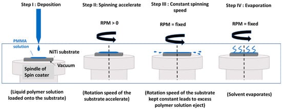
Figure 1.
Various stages of spinning process: (I) deposition; (II) spinning process; (III) constant spinning speed; (IV) evaporation.
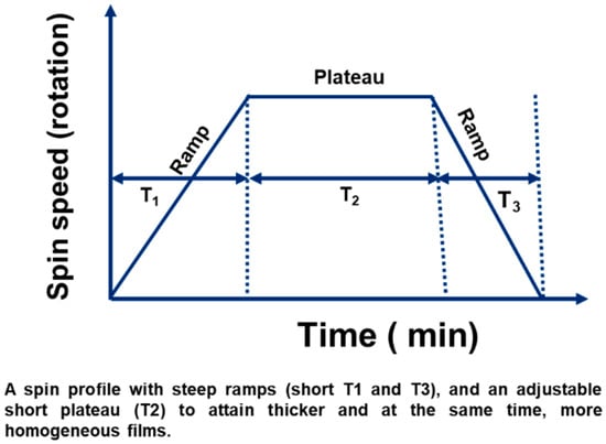
Figure 2.
Spin-coating profile of time versus rotation speed as a function of ramp and plateau. T3 is steeper compared to T1 to maintain a coating thickness that is thicker with fewer surface defects. The transient, time-integration scheme, Δt, and tolerances; 30 s total and rpm plateaus are correlated with this figure.
Spin coating is a widely used technique for depositing films of uniform thickness on planar substrates. In this process, a liquid melt or solution is applied to a rotating substrate, and during the transient stage, the combined action of radial and hydrodynamic (viscous) forces flattens the deposited liquid into a thin planar film [30]. With continued rotation, the film gradually becomes thinner, while the concentration of the PMMA solution and the rotation speed govern the uniformity and final thickness of the film on the NiTi surface. Under these conditions, a uniform liquid film rapidly forms and subsequently solidifies through solvent evaporation (or cooling, in the case of molten materials) [31]. The spin-coating process generally consists of two main stages: (i) the spin-off phase and (ii) the evaporation phase [32]. In the early spin-off phase, the angular velocity and rotation speed strongly influence how the polymer film spreads across the substrate. During the plateau stage of this phase, the film thickness stabilizes under constant spinning. In the latter evaporation phase, solvent removal dominates, causing further thinning of the film and enrichment of the nonvolatile solute, such as PMMA, as volatile solvents (e.g., toluene) evaporate. The final film thickness for Newtonian fluids can be expressed as a function of five parameters: the spin-coating duration, viscosity, density, angular velocity (or rotation per minute), and initial thickness of the deposited liquid layer [33,34]. In practice, however, spin coating is most often controlled by adjusting only the angular velocity and coating time. As a result, discrepancies frequently arise between the measured coating thickness and the theoretical predictions derived from Newtonian fluid models [35].
For a Newtonian, the equation for a volatile liquid film of thickness h on a rotating substrate is as follows [26]:
dh/dt = −2Kh3 − E
After inputting the expression, Equation (1) changes into
where the first term describes (−) hydrodynamic thinning due to centrifugal forces.
The second term (−E) accounts for thickness reduction due to the evaporation of volatile solvents.
If evaporation is negligible (E ≈ 0), the simplified (2) equation is as follows:
According to Emslie, Bonner, and Peck, the thickness of a Newtonian liquid on a rotating disk was calculated by differential equations in cylindrical polar coordinates.
For a nonvolatile viscous fluid on an infinite rotating disk, Emslie’s model was used as in [1].
Here, t is the time since the start of the process, ω is the angular velocity, r is the distance from the center of rotation, ρ is the density, η is the dynamic viscosity, and h is the thickness of the fluid layer, rather than of the dry thin film. Here, ∂h/∂t represents the rate of change of the thickness, and ∂h/∂r is the rate of spreading. If the film is considered initially uniform, this leads to a description of the fluid film thickness [19]. The integration of Equation (3) yields
Here, h0 represents the uniform thickness of the film at the start of the process (i.e., t = 0). As this model does not account for evaporation, it cannot be used to calculate the thickness of the final dry film. An approximate dry thickness can be calculated from the fluid film thickness by using the concentration of the solute and solution density. The various stages of the spin casting process are described in schematic diagram Figure 3a in early and latter stages. The rotational coordinate system of degree of rotation along Z axis is shown in Figure 3b and dimensions of substrate and coating layer along axis system is in Figure 3c. An effective model of Meyerhofer with the parameters and sensitivity (f) (η, rpm) can be produced showing the error after the evaporation effect and the applicability.
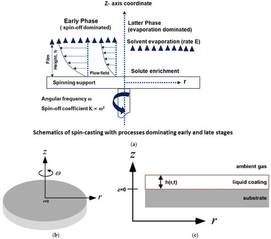
Figure 3.
(a) Schematic diagram of spin casting with process showing early and latter stages of coating process. (b) Schematic diagram of rotational coordinate system of degree of rotation along Z axis and (c) dimensions of substrate and coating layer along axis system.
To quantitatively estimate the thickness of the coating layer on a NiTi substrate, both simulation and experimental methods were employed to investigate the spin-coating process.
2. Simulation Method and Initial Parameters
2.1. Simulation Method
This study used COMSOL 6.3 Software Multiphysics to simulate the spin-coating process with a 2D axisymmetric laminar flow model with the moving mesh of a free surface without any swirl movement. The initial parameters were considered while evaporation effects were ignored. The dynamic viscosity is presented in Figure 4. The PMMA solution was prepared with toluene in the ratio of PMMA powder to toluene (1 gm/12 mL) that corresponded to 8.3 mol% and (1 gm/24 mL) that corresponded to the dynamic viscosity (mPa·s). The rpm–viscosity–volume had a significant effect on the estimated predicted coating thickness of the polymer. The parameters of the rotation of the spin coating were 100, 500, 2000, and 3200 rpm and the dynamic viscosities were 2, 6, and 11 mPa·s with a fixed dispense volume of 500 µL. The values of ρ, η = 2/6/11 mPa·s, γ, T, and RH were constants during the spin-coating process as the function of time (duration of the spin-coating process).
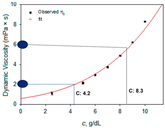
Figure 4.
Concentration versus dynamic viscosity that corresponds to specific dynamic viscosity.
Both the Emslie, Bonner, and Peck model and Meyerhofer model were used to describe the film thinning and final thickness. The initial volume of the polymer solution was taken into consideration as h0. Upon rotation, the solution started to spread along the substrate, which led to thinning to form the final polymer layer deposited on the surface. The moving mesh was of a free surface, with a contact angle of 90° with the substrate. This was a laminar flow with no swirl, with no slip in the boundary condition. Figure 5a–c displays the sketch profile of substrate with coating layer and its corresponding mesh pattern. Table 2 displays the input parameters such as various rotation speed and dynamic viscosities consider for this study.
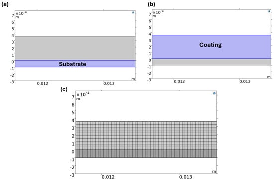
Figure 5.
(a–c) Sketch diagram of substrate and coating with meshing between substrate and coating.

Table 2.
Initial parameters of the spin-coating process at various dynamic viscosities and various rotation speeds and initial volume of the polymer solution.
2.2. Experimental Method
The polymer solution of PMMA with toluene dissolved in two ratios, 1:12 and 1:24 g/mL, for the selected concentrations of 8.3 and 4.2 g/mL. The solution was allowed to mix at 100 rpm for 12 h with a magnetic stirrer inside the beaker that was placed inside the glass chamber in an air medium. The concentration solution was added for the spin-coating method for the deposition of the film according to optimized parameters. The holder for the substrate was positioned using a vacuum chuck (400 Pennbrook Pkwy, Lansdale, PA, USA), and the motor allowed for the rotation of the substrate after the polymer solution was added. The experiments were repeated at least 2–3 times to calculate the statistical distribution of the coating thickness. The statistical deviation is within the range of ±0.001 µm thickness, which is considered negligible. The thickness was measured at various points both using a microcaliper as well as by cross-sectional image using a Keyence microscope. The Conventional PMMA powder was obtained from Sigma Aldrich (St. Louis, MO, USA) and had a molecular weight of 102,000 gmol−1. The solvent of toluene was purchased from Sigma Aldrich. Then, the solution was placed on the stirrer using a magnetic stirrer for miscibility for the formation of a clear solution. The solution was stirred for 24 h at 2 rpm for the concentrated solution. The spin coating was performed by the Laurell WS-400-6NPP spin coater with 650 series controller program software (Version 2), a digital micrometer with accuracy ± 0.0002 (Sigma Aldrich), and a microscope (Keyence). The process parameters were the acceleration profile and plateaus (Figure 3), actual rpm (500 and dispensed volume 500 µL; total time: 30 s; drying/curing protocol; post-curing at RT and 60 °C in a vacuum chamber), and environmental conditions (RT and RH; 99.87%).
3. Results and Discussion
Figure 6a,b represent the distribution of the velocity (m/s) along the surface from the center to the edge area. The spin-coating process was carried out for 30 s; the color bar shows the values of the velocity throughout the surface. The color bar shows the gradient of the velocity from the center of the rotating disc, 0.2 m/s at the center, to 1.5 m/s at the edge. At the edge, a higher velocity of the rotation speed is observed, which matches well with Figure 6b with the arrow volume velocity. The PMMA layer becomes thinner with the increased rotational speed.

Figure 6.
(a,b) Velocity magnitude and velocity field throughout the rotating disc on the surface of the substrate from the edge to the center displaying the path of rotation of the COMSOL simulation.
Figure 7a–c represent the pressure distribution along the substrate towards the coating layer at a fixed rpm of 2000, with a duration of the coating process of 30 s, for various viscosities at 2, 6, and 11 mPa·s. The color bar values show that there is a negligible difference in the pressure values despite the various viscosities. The pressure distribution remains the same along the configuration of the system from the substrate towards the coating layers. This result signifies that the pressure distribution remained the same along the assembly of the substrate towards the coating layers despite the various dynamic viscosities. Figure 8A represents the final layer of polymer deposited with time at a viscosity of 2 mPa·s. At various rpm values, it was observed that at a lower rotation of 100 rpm, the coating thickness predicted by COMSOL and the points were marked by the Emslie, Bonner, and Pec model using Equation (7), and a match was plotted. It was observed that at lower rpm, there was a slight deviation in matching; however, at higher rpm, there was complete agreement on the matching of the coating thickness and model values. The model was observed for two different viscosities at 6 and 11 mPa·s, which show similar trends of slight deviation at lower rpm but are well matched at higher rpm. The curve of the thickness slope decreases with the duration of the coating process.
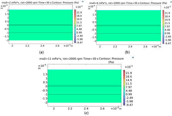
Figure 7.
(a–c). Pressure distribution along substrate and coating system at different viscosities with constant rpm for fixed duration of time of COMSOL simulation.
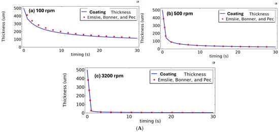
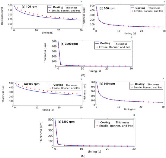
Figure 8.
(A) Coating thicknesses at various rpm values for dynamic viscosity at 2 mPa·s using COMSOL simulation. The line shows the coating thickness, and the point shows the estimation from the Emslie, Bonner, and Peck model. (B) Coating thicknesses at various rpm values for dynamic viscosity at 6 mPa·s using COMSOL simulation. The line shows the coating thickness, and the point shows the estimation from the Emslie, Bonner, and Peck model. (C) Coating thicknesses at various rpm values for dynamic viscosity at 11 mPa·s using COMSOL simulation. The line shows the coating thickness, and the point shows the estimation from the Emslie, Bonner, and Peck model.
Combining the above rotation process, Figure 9c represents the thicknesses of the coating layer at various viscosities at a fixed time of the coating process. It was observed that at a lower rpm value of 100, the final thickness after 30 s of rotation at 2 mPa·s reached 125 µm; however, at an increase in viscosity to 6 mPa·s, the final thickness at 100 rpm reached the value of 200 µm. At a higher dynamic viscosity of 11 mPa·s, the final thickness reached up to 250 µm at a lower rotation per minute of 100 rpm.

Figure 9.
(a–c) Thickness as a function of time at various rpm values for three different viscosities using COMSOL simulation.
However, upon increasing the rpm, the final coating thickness was effectively reduced. At higher rpm values of 2000 and 3200 rpm, despite the various viscosities, the final thickness of the coating reaches a minimum value. However, at 500 rpm, the final coating thickness varies depending on the viscosity. At lower viscosity, the final value of the coating is lower than that at higher viscosity towards lower speed, which may be due to the higher concentration of the polymer solution. A combined plot of the variation in the coating thickness is shown in Figure 10. At a higher concentration, the final coating thickness reaches 250 µm, with the thickness reducing with the varying viscosity. The trend is also visible at 500 rpm for various viscosities. However, at higher rpm values of 2000, 3200, the layer reaches ultra-thin coating thickness despite the various viscosities.
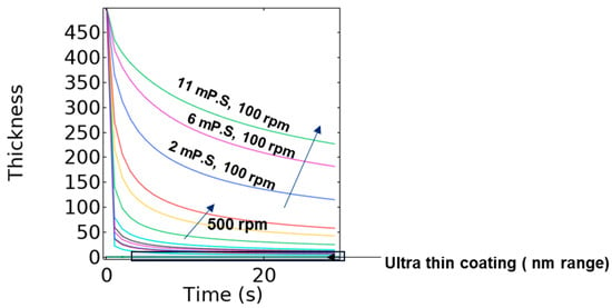
Figure 10.
Thickness versus time for various viscosities and rpm values from simulation output. The arrow indicates at different viscosities from lower dynamic viscosity ( 2 mPa·s) to higher viscosity (11 mPa·s).
Figure 11 represents the thicknesses of the PMMA layer achieved at various viscosities and rotations of the substrate in the coating process. The study findings reveal that the final thickness of the coating layer was achieved by considering the amount of polymer solution used in this study. Figure 11 displays the good match between the simulation findings and experimental approach at 500 rpm for 2 mPa·s for 150 µm thickness; however, a mismatch is observed at the higher speed. This may vary due to the ambiguity at the initial volume of the polymer solution taken into consideration at lower viscosity.
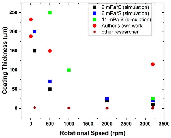
Figure 11.
Thickness versus rotation for various viscosities from simulation without error bars and experiments and other researchers [36,37,38,39] and authors own work [9,22,35].
In this work, a range of 100–300 µm for the thickness of the PMMA coating layer was achievable on a NiTi surface with reduction in the MAE ≤ 10% across the rpm–viscosity domain in the simulation and ≥10% reduction in the experimental iterations. This simulation approach estimating the coating thickness prior to the experimental approach could save material/time. The illustrative experimental datum (N = 1) was not used to validate the model, nor to estimate error or reproducibility.
The final thickness of the coating layer is displayed in Figure 12. It was observed that a PMMA coating thickness of 150 µm was achieved on the surface of a NiTi alloy. There is a slight deviation of 25 µm in the coating thickness as compared to the simulation prediction, which may be due to surface roughness. In the simulation process, we considered the smooth surface; however, in the experimental process, we considered the NiTi surface with laser lines for more adhesion of the PMMA layer to the surface. The laser line acts as a channel for the infiltration of the PMMA solution on the NiTi surface that may adhere as a mechanical lock and key pattern. This may lead to minor ambiguity.
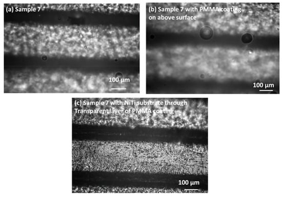
Figure 12.
(a–c) The PMMA coating thickness achieved at 500 rpm at a dynamic viscosity of 2 mPa·s on the NiTi surface.
The correlation between the simulation study of the spin-coating process is an important finding to estimate the coating thickness before the experimental approach. As the spin-coating process wastes a lot of solution during the spinning process, this simulation limits the material waste. The correlation between the simulation and experimental results from authors on previous results [8,11,25] and the ultra-thin coatings of other researchers [1,26,27,28] represents the match. A good match is exhibited at a higher 3200 rpm for ultra-thin coating; however, there is a lack of data on the thicker coating in the spin-coating process besides the author’s previous work. The simulation does not consider evaporation; however, in the experiment, the final coating thickness is measured after drying the coating layer on the substrate. So, at lower rpm, there is a slight deviation that may arise due to the evaporation effect.
4. Conclusions
The Spin-Coating Simulation of PMMA Solution on the Surface of SM NiTi presents a study on the fabrication of PMMA coatings on NiTi alloys using the spin-coating technique, combining numerical simulation with COMSOL Multiphysics and experimental validation. The topic is of interest due to the biomedical and technological applications of NiTi-PMMA composites, and the article shows consistency between simulated and observed trends. This study investigates the depletion of thin coating layers under the combined influence of the substrate configuration and coating process parameters. A simulation framework was developed (COMSOL Multiphysics) to suggest the surface-averaged thickness of films produced by spin coating. The model examines the effects of the initial surface profile, dispensed volume, solvent vapor pressure, relative humidity, initial viscosity, and substrate rotation speed on the coating geometry. Among these, the dispensed volume, solvent vapor pressure, initial viscosity, and wafer rotation speed emerge as the most effective parameters for controlling surface coverage; the average film thickness is derived directly from the model. Parametric analysis indicates that a higher dynamic viscosity of 11 mPa·s and 2000 rpm constitute the optimal conditions for achieving the desired coating thickness. There is a good match in ultra-thin coating resulting from 5–25 µm at a higher speed of 3200 rpm. Evaporation is not included in the simulation but is accounted for in the experimental study. Overall, the model provides a quantitative guide for the coating thickness as a function of the viscosity and rotation parameters, enabling practical implementation and process tuning in spin coating. NiTi-PMMA composites can be applied in the biomedical field as actuators.
Funding
This research was funded by the EU structural fund project FerrMion (CZ.02.01.01/00/22_008/0004591).
Institutional Review Board Statement
Not applicable.
Informed Consent Statement
Not applicable.
Data Availability Statement
Dataset of Spin Coating Simulation of PMMA Solution on the Surface of SM NiTi [Dataset]. Zenodo. https://doi.org/10.5281/zenodo.16752070 (accessed on 6 August 2025) and other data will be made available upon request.
Conflicts of Interest
The author declares no conflict of interest.
References
- Butt, M.A. Thin-Film Coating Methods: A Successful Marriage of High-Quality and Cost-Effectiveness—A Brief Exploration. Coatings 2022, 12, 1115. [Google Scholar] [CrossRef]
- Krebs, F.C. Fabrication and processing of polymer solar cells: A review of printing and coating techniques. Sol. Energy Mater. Sol. Cells 2009, 93, 394–412. [Google Scholar] [CrossRef]
- Lim, S.-L.; Chen, E.-C.; Chen, C.-Y.; Ong, K.-H.; Chen, Z.-K.; Meng, H.-F. High performance organic photovoltaic cells with blade-coated active layers. Sol. Energy Mater. Sol. Cells 2012, 107, 292–297. [Google Scholar] [CrossRef]
- Aziz, F.; Ismail, A. Spray coating methods for polymer solar cells fabrication: A review. Mater. Sci. Semicond. Process. 2015, 39, 416–425. [Google Scholar] [CrossRef]
- Hofacker, S.; Mechtel, M.; Mager, M.; Kraus, H. Sol–gel: A new tool for coatings chemistry. Prog. Org. Coatings 2002, 45, 159–164. [Google Scholar] [CrossRef]
- Chougule, M.; Sen, S.; Patil, V. Fabrication of nanostructured ZnO thin film sensor for NO2 monitoring. Ceram. Int. 2012, 38, 2685–2692. [Google Scholar] [CrossRef]
- Khuspe, G.; Sakhare, R.; Navale, S.; Chougule, M.; Kolekar, Y.; Mulik, R.N.; Pawar, R.; Lee, C.; Patil, V. Nanostructured SnO2 thin films for NO2 gas sensing applications. Ceram. Int. 2013, 39, 8673–8679. [Google Scholar] [CrossRef]
- Gohel, J.V. Effect of type of solvent on the sol-gel spin coated CZTS thin films. Phys. Astron. Int. J. 2017, 1, 126–129. [Google Scholar] [CrossRef][Green Version]
- Samal, S.; Kosjakova, O.; Vokoun, D.; Stachiv, I. Shape Memory Behaviour of PMMA-Coated NiTi Alloy under Thermal Cycle. Polymers 2022, 14, 2932. [Google Scholar] [CrossRef]
- Chaki, S.H.; Deshpande, M.; Tailor, J.P. Characterization of CuS nanocrystalline thin films synthesized by chemical bath deposition and dip coating techniques. Thin Solid. Films 2014, 550, 291–297. [Google Scholar] [CrossRef]
- Chaki, S.H.; Mahato, K.S.; Malek, T.J.; Deshpande, M. CuAlS 2 thin films—Dip coating deposition and characterization. J. Sci. Adv. Mater. Devices 2017, 2, 215–224. [Google Scholar] [CrossRef]
- Das, H.T.; Vinoth, S.; Thirumoorthi, M.; Alshahrani, T.; Hegazy, H.H.; Somaily, H.H.; Shkir, M.; Aifaify, S. Tuning the optical, electrical, and optoelectronic properties of CuO thin films fabricated by facile SILAR dip—Coating technique for photosensing applications. J. Inorg. Organomet. Polym. Mater. 2021, 31, 2606–2614. [Google Scholar] [CrossRef]
- Maldar, P.; Gaikwad, M.; Mane, A.; Nikam, S.; Desai, S.; Giri, S.; Sarkar, A.; Moholkar, A. Fabrication of Cu2CoSnS4 thin films by a facile spray pyrolysis for photovoltaic application. Sol. Energy 2017, 158, 89–99. [Google Scholar] [CrossRef]
- Srinivasulu, T.; Saritha, K.; Reddy, K.R. Synthesis and characterization of Fe-doped ZnO thin films deposited by chemical spray pyrolysis. Mod. Electron. Mater. 2017, 3, 76–85. [Google Scholar] [CrossRef]
- Moumen, A.; Hartiti, B.; Comini, E.; El Khalidi, Z.; Arachchige, H.M.M.; Fadili, S.; Thevenin, P. Preparation and characterization of nanostructured CuO thin films using spray pyrolysis technique. Superlattices Microstruct. 2019, 127, 2–10. [Google Scholar] [CrossRef]
- Huber, C.; Stein, B.; Kalt, H. Plasma-enhanced chemical vapor deposition of amorphous silicon carbonitride: Deposition temperature dependence of bonding structure, refractive index, mechanical stress and their aging under ambient air. Thin Solid. Films 2017, 634, 66–72. [Google Scholar] [CrossRef]
- Li, D.; Gautier, N.; Dey, B.; Bulou, S.; Richard-Plouet, M.; Ravisy, W.; Goullet, A.; Choquet, P.; Granier, A. TEM analysis of photocatalytic TiO2 thin films deposited on polymer substrates by low-temperature ICP-PECVD. Appl. Surf. Sci. 2019, 491, 116–122. [Google Scholar] [CrossRef]
- Rossnagel, S.M. Thin film deposition with physical vapor deposition and related technologies. J. Vac. Sci. Technol. A 2003, 21, S74–S87. [Google Scholar] [CrossRef]
- Konar, R.; Nessim, G.D. A mini-review focusing on ambient-pressure chemical vapor deposition (AP-CVD) based synthesis of layered transition metal selenides for energy storage applications. Mater. Adv. 2022, 3, 4471–4488. [Google Scholar] [CrossRef]
- Dewang, Y.; Sharma, V.; Baliyan, V.K.; Soundappan, T.; Singla, Y.K. Research Progress in Electroactive Polymers for Soft Robotics and Artificial Muscle Applications. Polymers 2025, 17, 746. [Google Scholar] [CrossRef]
- Nematollahi, M.; Baghbaderani, K.S.; Amerinatanzi, A.; Zamanian, H.; Elahinia, M. Application of NiTi in Assistive and Rehabilitation Devices: A Review. Bioengineering 2019, 6, 37. [Google Scholar] [CrossRef]
- Samal, S.; Kosjakova, O. Surface feature of PMMA films on NiTi alloy substrate by the spin coating method. Ceram. Int. 2022, 49, 24370–24378. [Google Scholar] [CrossRef]
- Semaltianos, N. Spin-coated PMMA films. Microelectron. J. 2007, 38, 754–761. [Google Scholar] [CrossRef]
- Na, J.Y.; Kang, B.; Sin, D.H.; Cho, K.; Park, Y.D. Understanding Solidification of Polythiophene Thin Films during Spin-Coating: Effects of Spin-Coating Time and Processing Additives. Sci. Rep. 2015, 5, srep13288. [Google Scholar] [CrossRef] [PubMed]
- Liu, W.; Chen, P.G.; Ouazzani, J.; Liu, Q. Thermocapillary flow transition in an evaporating liquid layer in a heated cylindrical cell. Int. J. Heat. Mass. Transf. 2020, 153, 119587. [Google Scholar] [CrossRef]
- Park, D.-S.; Park, K.-S. Optimal functional surface coating considering internal flow behavior of viscous-liquids driven by vertical ultrasonic waves. Results Phys. 2021, 25, 104255. [Google Scholar] [CrossRef]
- Chang, R.-C.; Chen, F.-Y.; Yang, P. Dynamic mechanical properties of photo resist thin films. J. Mech. Sci. Technol. 2007, 21, 1739–1744. [Google Scholar] [CrossRef]
- Danglad-Flores, J.; Eickelmann, S.; Riegler, H. Deposition of polymer films by spin casting: A quantitative analysis. Chem. Eng. Sci. 2018, 179, 257–264. [Google Scholar] [CrossRef]
- Mendhe, A.C. Spin Coating: Easy Technique for Thin Films. In Simple Chemical Methods for Thin Film Deposition; Sankapal, B.R., Ennaoui, A., Gupta, R.B., Lokhande, C.D., Eds.; Springer: Singapore, 2023. [Google Scholar] [CrossRef]
- Cregan, V.; O’Brien, S. A note on spin-coating with small evaporation. J. Colloid. Interface Sci. 2007, 314, 324–328. [Google Scholar] [CrossRef]
- Huang, Y.-Y.; Chou, K.-S. Studies on the spin coating process of silica films. Ceram. Int. 2003, 29, 485–493. [Google Scholar] [CrossRef]
- Schwartz, L.W.; Roy, R.V. Theoretical and numerical results for spin coating of viscous liquids. Phys. Fluids 2004, 16, 569–584. [Google Scholar] [CrossRef]
- Meyerhofer, D. Characteristics of resist films produced by spinning. J. Appl. Phys. 1978, 49, 3993–3997. [Google Scholar] [CrossRef]
- Emslie, A.G.; Bonner, F.T.; Peck, L.G. Flow of a viscous liquid on a rotating disk. J. Appl. Phys. 1958, 29, 858–862. [Google Scholar] [CrossRef]
- Samal, S.; Tyc, O.; Heller, L.; Šittner, P.; Malik, M.; Poddar, P.; Catauro, M.; Blanco, I. Study of Interfacial Adhesion between Nickel-Titanium Shape Memory Alloy and a Polymer Matrix by Laser Surface Pattern. Appl. Sci. 2020, 10, 2172. [Google Scholar] [CrossRef]
- Lee, U.G.; Kim, W.-B.; Han, D.H.; Chung, H.S. A Modified Equation for Thickness of the Film Fabricated by Spin Coating. Symmetry 2019, 11, 1183. [Google Scholar] [CrossRef]
- Tajima, K.; Kubota, T.; Jeong, C.Y. Preparation of electrochromic thin films by humidity-controlled spin coating. Thin Solid. Films 2022, 758, 139412. [Google Scholar] [CrossRef]
- Lawrence, C.J. The mechanics of spin coating of polymer films. Phys. Fluids 1988, 31, 2786–2795. [Google Scholar] [CrossRef]
- Danglad-Flores, J.; Eickelmann, S.; Riegler, H. Evaporation behavior of a thinning liquid film in a spin coating setup: Comparison between calculation and experiment. Eng. Rep. 2021, 3, e12390. [Google Scholar] [CrossRef]
Disclaimer/Publisher’s Note: The statements, opinions and data contained in all publications are solely those of the individual author(s) and contributor(s) and not of MDPI and/or the editor(s). MDPI and/or the editor(s) disclaim responsibility for any injury to people or property resulting from any ideas, methods, instructions or products referred to in the content. |
© 2025 by the author. Licensee MDPI, Basel, Switzerland. This article is an open access article distributed under the terms and conditions of the Creative Commons Attribution (CC BY) license (https://creativecommons.org/licenses/by/4.0/).