Abstract
This study proposed a new magnetic abrasive finishing (MAF) method, in which a 6-axis robot with a magnetic machining tool was used to polish the inner surfaces of curved tubes. We have also developed a magnetic machining tool jig, which can be fixed at the front of the 6-axis robot, rotating freely and suitable for polishing the inner surfaces of curved tubes. In this study, we focused on investigating the machining parameters in the initial machining stage and precision finishing stage. Based on the characteristics of machining parameters, a multi-stage MAF process was conducted to obtain an inner surface with high quality and high efficiency. The experimental results showed that both the roughness Ra and Rz of inner surface in the initial machining stage significantly decreased with the increase in the mixed magnetic abrasives, to as low as less than 20 nm Ra in the precision finishing stage when the machining parameters were appropriately adjusted. In addition, the roughness Ra of inner surface could be further reduced to less than 10 nm Ra in the multi-stage MAF process. Finally, the magnetic flux density cloud map and the magnetic field line distribution map were analyzed in Ansys Maxwell.
1. Introduction
There has been an increased demand for advanced cleaning technologies (ultra clean technologies) in various industries, such as semiconductors, nuclear energy, pharmaceuticals, and aerospace. One of the fields of ultra-clean technology is the manufacturing technology of pipes (clean pipes) for both the high-purity gases used in the semiconductor manufacturing process and the transportation of high-purity fluids used in the medical industry. When using the inner surface of pipelines with grid surface roughness, pollutants are easily attached to small pits on the inner surface. Accumulation of a large amount of pollutants can lead to corrosion. In some cases, cracks and fractures may even occur [1,2]. In the medical industry, the use of transportation pipelines with a lower surface quality may lead to the deterioration of drug solutions, bacterial infections, and even pose a threat to human life [3]. To avoid pollutants adhering or remaining on the inner surface of the conveying pipeline, it is usually necessary to perform nanoscale precision machining greater than 100nm Ra on the inner surface. In addition, the precision machining is also required on the inner surfaces of pipes with various shapes, such as irregular pipelines, bent pipes, etc.
Currently, the inner surface finishing of clean pipes is mainly achieved through the electrolytic process method. The inner surface finishing of the curved tubes and other tubes requires manual machining of the bent parts before the electrolytic process. However, this machining method has some defects, such as manual machining affecting the accuracy of the processing surface, and difficulty in handling harmful metals dissolved in the electrolyte after electrolytic process. Therefore, it is required to develop a new precision machining technology for inner surfaces, to replace existing machining methods. Magnetic abrasive finishing (MAF) is a precision machining method that is particularly suitable for polishing the inner surfaces of tubular workpieces [4,5,6,7,8]. However, due to its disadvantage of insufficient machining force, it is necessary to enhance the magnetic attraction from external sources during processing [9,10,11]. If the distance between the magnetic poles of the workpiece is reduced, it may cause unstable processing. In extreme cases, the use of magnetic particles for inner surface magnetic finishing in large-diameter curved tubes or thick-walled tubes can sometimes make magnetic particles trapped and unable to be processed properly, and even result in the differences in surface roughness between the inner and outer surfaces of the bent part. In order to solve the above problems, some researchers are committed to optimizing the machining parameters and improving the machining tools. Zhang et al. proposed using a “pressuring bag” to increase the finishing pressure in the finishing system [12]. Yamaguchi et al. suggested that using a multiple pole-tip system with a high speed (up to 30,000 min−1) polished the inner surface of a tube; the experimental results proved that finishing efficiency can be obviously improved by using this method [13,14]. Zou et al. developed an auxiliary magnetic jig to polish the inner surface of a thick-wall tube, the experimental results revealed that the combination of external magnetic poles and an internal auxiliary magnetic jig effectively improved the machining force [15,16]. Muhamad et al. developed a complex polishing method that combining magnetic abrasive finishing with an electrolytic process to polish the inner surface of AA6063-T1 tubes. The experimental results showed that both the inner surface quality and the finishing efficiency can be improved, with polishing efficiency increasing by over 80% [17,18,19]. Furthermore, Wang et al. reported that magnetic field-assisted polishing technology is also effective for polishing both the three-dimensional surfaces and freeform surfaces with nanometric surface finish [20,21]. Presently, there is relatively little research on the internal surface machining of complex shaped tubes, due to its shape limitation. Singh et al. proposed internal finishing of complex shaped tubes with sintered magnetic abrasive. He mainly studied the influence of rotational speed on the quality of internal surface finishing through a large number of experiments when sintered magnetic abrasive was used in a MAF process [22]. Han et al. conducted a lot of research on optimizing relevant machining parameters for a MAF process for curved tubes. They applied the orthogonal experimental method to conduct grinding experiments on the inner surface of titanium alloy bends, and combined the experimental data to analyze and optimize the process parameters. By comparing the surface roughness and morphology changes in titanium alloy bend pipes before and after finishing, the feasibility and reliability of using MAF technology to smooth the inner surfaces of the bend pipes were verified [23].
It has been proven that a magnetic machining jig can be used as an effective means of improving the machining force in the MAF process. Therefore, this study proposed a new magnetic abrasive finishing method, where the jig of a magnetic machining tool was used to polish the inner surfaces of curved tubes. In this study, the machining parameters of the initial processing stage and the finishing stage were investigated. According to the characteristics of polishing parameters, a multi-level MAF process was performed to obtain inner surface with a higher quality. Considering the service life of magnetic abrasive particles, they were replaced after each finishing stage (per 10 min). After each finishing stage, the changes in surface roughness Ra and Rz were evaluated using a contact surface roughness meter (SV-624-3D, Mitutoyo, Utsunomiya, Japan), and the inner surface was observed using a metallurgical microscope (Super View W1, CHOTEST, Shenzhen, China). Finally, the magnetic flux density cloud map and the magnetic field line distribution map were analyzed by using Ansys Maxwell 19.2 soft.
2. Machining Principle and Experimental Procedure
2.1. Machining Principle
Figure 1 shows the machining principle of magnetic abrasive finishing (MAF) for the inner surface finishing of a curved tube. The external magnetic poles are fixed to the jig of a magnetic machining tool on the outside of the workpiece, and the internal and external magnetic poles forms a closed magnetic circuit, which generates greater magnetic attraction, applying processing pressure to the inner surface of the workpiece. The internal magnetic pole follows the external magnetic pole, rotating and feeding along the axis direction of the curved tube, resulting in relative friction between the mixed magnetic abrasive particles and the inner surface of the curved tube. Thus, the inner surface finishing of the curved tube can be achieved. Although it looks like the machining principle of straight tube, the curved tube always remains stationary, and only external magnetic poles perform a rotational motion during the MAF process. Compared to polishing a straight tube, the relative rubbing speed between abrasive and inner surface is significantly smaller during the MAF process for a curved tube.

Figure 1.
Schematic diagram of the machining principle for the inner surfaces of curved tubes.
The mixed magnetic abrasive particles are absorbed on the ends of the internal magnetic poles. In the MAF process, in addition to magnetic force, gravity, and centrifugal force, mixed magnetic particles are also subjected to machining pressure from magnetic machining tools. Thus, the machining pressure Fr consists of the magnetic force generated between the magnetic poles, the centrifugal force, and gravity of the rotating magnetic machining tool.
2.2. Experimental Setup and Experimental Procedure
As shown in Figure 2, a 6 axis robot is the main part of the experimental device for polishing the inner surface of the curved tube fixed with a chuck. A magnetic machining fixture with an external magnetic pole is suspended at the front end of the 6-axis robot’s arm. The external magnetic poles perform the feeding motion along the axis direction of the curved tube through the 6-axis robot’s arm. In addition, they rotate synchronously through the transmission power from the external motor. The internal magnetic processing tool and external magnetic processing jig form an “N–S–N–S” closed magnetic field circuit, thereby increasing the strength of the magnetic field force.
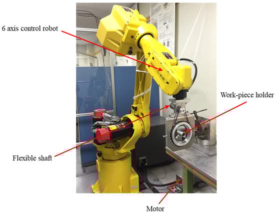
Figure 2.
External view of the experimental device.
A new type of external magnetic machining jig was developed in this study, based on the traditional MAF process, to improve the magnetic field strength in the polishing area. The external magnetic machining jig consists of a yoke, pulley and bearing, as shown in Figure 3a. The size and material of external magnetic poles are 10 to 10 × 10 Nd–Fe–B rare earth permanent magnets (N52), their magnetic field strength is 0.5 T, and they are disposed at 90° on the yoke by bolts and iron sleeves. The work-piece gap between external magnetic poles and internal surface of the curved tube is adjusted by rotating the sleeve.
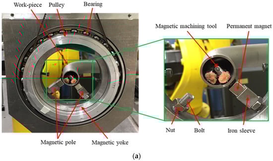
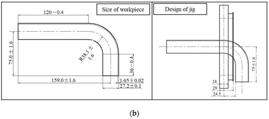
Figure 3.
External magnetic machining jig. (a) External view of the magnetic machining jig; (b) the basic size of the curved tube workpiece and design of the magnetic machining jig.
In addition, it was found through a simulation that the interference was most likely to occur at the position where the curved tube was 90°. During the MAF process, it is necessary to consider the interference between the external magnetic machining tool and the inner surface of the workpiece. Figure 3b shows the basic size of the curved tube work-piece, and the design of the magnetic machining jig. When the magnetic machining jig moved to the bending location of the workpiece, the motion trajectory changed from linear motion to an arc motion. The distance of the magnetic machining jig from the center of the yoke to the outer edge of the pulley flange should not exceed 24.5 mm, and the inner diameter of the yoke should reach more than 76.6 mm, when the magnetic machining jig runs to a sinuosity position. Therefore, in order to avoid the interference, the thickness of the yoke was set to 18 mm and the thickness of the pulley was set to 29 mm.
The internal magnetic machining tool is composed of a universal joint with high free movement. Permanent magnets with opposite poles are fixed on both ends of the universal joint. In order to avoid collisions between the inner surface of the curved tube and the magnetic machining tool, the magnetic poles of magnetic machining tool are wrapped with non-woven fabric, as shown in Figure 4. The mixed magnetic abrasive is adsorbed on the magnetic poles with the non-woven fabric.
Figure 4.
External view of the internal magnetic machining tool.
3. Experimental Results
The MAF process was divided into two machining stages: the initial machining stage and precision finishing stage. This study focused on investigating the total usage of mixed magnetic abrasives, working gaps, rotational speed and combinations of abrasives with different particle sizes in the initial machining stage. Moreover, the working gap and feeding speed were also investigated in the precision finishing stage.
3.1. Initial Machining Stage
3.1.1. Experimental Conditions
The experimental conditions of the constant machining parameters in the initial machining stage are shown in Table 1. The workpiece is an SUS304 stainless steel curved tube with a 90° right angle. The finishing length of the workpiece is limited to 70 mm in the curved area. The feeding speed of the external poles is set to 40 mm/min. The oil polishing fluid is used to mix the electrolytic iron particles with the KMX magnetic abrasive. The machining time is selected as 60 min in the initial machining stage, and each machining stage is 10 min. After each machining stage, the workpiece was cleaned, weight measured, and surface roughness measured.

Table 1.
Experimental conditions of the constant machining parameters in the initial machining stage.
- ♦
- The experimental conditions of experiment 1 are shown in Table 2. The working gap between the internal and external magnets is 4 mm, and the rotational speed is 360 rpm. To investigate the effect of the total usage of the mixed magnetic abrasive on the finishing characteristics, the total usage of the mixed magnetic abrasive as a variable parameter is 0.6 g (Cond. 1), 0.36 g (Cond. 2), and 0.84 g (Cond. 3), respectively, and the ratio of electrolytic iron particles to the KMX magnetic abrasive is 2:1.
Table 2. Experimental conditions with different total usage of mixed magnetic abrasive.
- ♦
- The experimental conditions of experiment 2 are shown in Table 3. The total usage of the mixed magnetic abrasive is 0.6 g, and the rotational speed is 360 rpm. To investigate the effect of the working gap on the finishing characteristics, the working gap as a variable parameter is 3 mm (Cond. 1), 4 mm (Cond. 2), and 5 mm (Cond. 3), respectively.
Table 3. Experimental conditions with different working gaps.
- ♦
- The experimental conditions of experiment 3 are shown in Table 4. The working gap between the internal and external magnets is 4 mm, and the total usage of the mixed magnetic abrasive is 0.6 g. To investigate the effect of the rotational speed on the finishing characteristics, the rotational speed as a variable parameter is 240 (Cond. 1), 360 (Cond. 2), and 480 rpm (Cond. 3), respectively.
Table 4. Experimental conditions with different rotational speeds.
- ♦
- The experimental conditions of experiment 4 are shown in Table 5. The working gap between the internal and external magnets is 4 mm, and the rotational speed is 360 rpm. To investigate the effect of the abrasive combinations with different particle sizes on the finishing characteristics, the detailed abrasives combinations are, respectively, described in Cond. 1, Cond. 2, Cond. 3.
Table 5. Experimental conditions of abrasive combinations with different particle sizes.
3.1.2. Experimental Results
The change in surface roughness Ra, Rz, and material removal M in the conditions with different total supply quantities of the mixed magnetic abrasive are shown in Figure 5. From the experimental results as shown in Figure 5a,b, it is seen that the roughness Ra and Rz of the inner surface in Cond. 1 were remarkably less than that in Cond. 2 and Cond. 3. Additionally, the maximum material removal M was obtained in Cond. 3. Increasing the supply of mixed magnetic abrasives may improve processing efficiency. However, when the supply quantity of the mixed magnetic abrasive exceeded 0.84 g, it was observed that the mixed magnetic abrasive particles adsorbed on the magnet tool with a spontaneous stirring phenomenon. Due to an excessive increase in the supply of the mixed magnetic abrasive, the attraction of the external mixed magnetic abrasive particles squeezed on the inner surface of the bend decreases. Moreover, an excessive reduction in the supply of the mixed magnetic abrasives results in very weak polishing effects of the abrasives. Thus, the optimal supply quantity of the mixed magnetic abrasive grains was 0.4 g electrolytic iron powder and 0.2 g KMX magnetic abrasive particles.
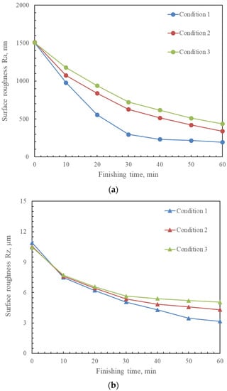
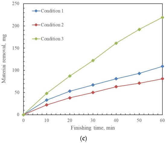
Figure 5.
Changes in surface roughness Ra, Rz and material removal M in the conditions, with different total supply quantities of mixed magnetic abrasive after 60 min MAF process. (a) Change in surface roughness Ra; (b) change in surface roughness Rz; (c) change in material removal M.
Figure 6 shows the change in surface roughness Ra, Rz, and material removal M in the conditions with different working gaps. It is recognized that the roughness Ra and Rz of inner surface in Cond. 1 and Cond. 2 were obviously less than that in Cond. 3. Moreover, the material removal M in Cond. 3 was clearly more than that in the other conditions. Focusing on the changes in the number of surfaces during the processing stage every 10 min, we found that the surface roughness of the inner tube significantly decreases with a decrease in the working gap between the magnetic poles of the workpiece. By reducing the working gap between the magnetic poles of the workpiece, the machining force was increased, and the machining efficiency was improved. Hence, the optimal working gap between the magnetic poles of the workpiece was considered as 3 mm in the initial machining stage.
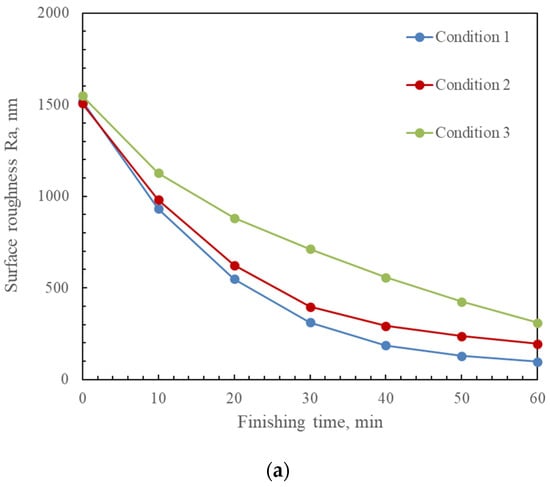

Figure 6.
Change in surface roughness Ra, Rz, and material removal M in the conditions with different working gaps after 60 min of MAF process. (a) Change in surface roughness Ra; (b) change in surface roughness Rz; (c) change in material removal M.
The change in surface roughness Ra, Rz, and material removal M in the conditions with different rotational speeds are shown in Figure 7. According to the experimental results shown in Figure 7a,b, it is regarded that the roughness Ra and Rz of the inner surface in Cond. 2 were evidently less than that in Cond. 1 and Cond. 3. However, the maximum material removal M was obtained in Cond. 3. As the rotational speed increased, the machining efficiency increased. On the other hand, the centrifugal force and the machining force also increased. However, an excessive increase in rotational speed led to an increase in centrifugal force, which caused the force to exceed the critical pressure. Furthermore, internal magnetic machining tools generated vibrations as the rotational speed increased, which also affected surface quality. Therefore, the optimum condition was obtained when the rotational speed was 360 min−1.
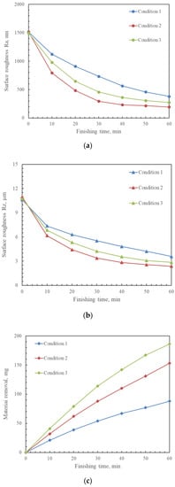
Figure 7.
Change in surface roughness Ra, Rz, and material removal M in different rotational speeds after 60 min of MAF process. (a) Change in surface roughness Ra; (b) change in surface roughness Rz; (c) change in material removal M.
Figure 8 shows the change in surface roughness Ra, Rz, and material removal M in the conditions of abrasive combinations with different particle sizes. It is indicated that the roughness Ra and Rz of inner surface in Cond. 3 were significantly less than that in Cond. 2 and Cond. 3. Furthermore, the maximum material removal M was obtained in Cond. 1. From the experimental results, the roughness Ra and Rz of the inner surface could be efficiently decreased by using the electrolytic iron powder with a large particle size in the first half of MAF process. Then, the roughness Ra and Rz of the inner surface could be further decreased by using the electrolytic iron powder with a 149 µm particle size in the second half of MAF process.
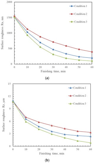
Figure 8.
Change in surface roughness Ra, Rz, and material removal M in the conditions of abrasive combinations with different particle sizes after 60 min of MAF process. (a) Change in surface roughness Ra; (b) change in surface roughness Rz; (c) change in material removal M.
3.2. Precision Finishing Stage
3.2.1. Experimental Conditions
Table 6 shows the experimental conditions of constant machining parameters in the precision finishing stage. The rotational speed of the external poles is 360 rpm. The total usage of the mixed magnetic abrasive is 0.6 g, and the ratio of electrolytic iron particles to KMX magnetic abrasive is 2:1. The other experimental conditions are the same as those in the initial machining stage.
Table 6.
Experimental conditions of constant machining parameters in the precision finishing stage.
- ♦
- Table 7 shows the experimental conditions of experiment 5. The feeding speed is 40 mm/min. To investigate the effect of the working gap on the finishing characteristics in the precision finishing stage, the working gap as a variable parameter is 3, 4, and 5 mm, respectively.
Table 7. Experimental conditions with different working gaps.
- ♦
- Table 8 shows the experimental conditions of experiment 6. The working gap is 4 mm. To investigate the effect of the feeding speed on the finishing characteristics in the precision finishing stage, the feeding speed as a variable parameter is 20, 40, and 80 mm/min, respectively.
Table 8. Experimental conditions with different working gap.
3.2.2. Experimental Results
The change in surface roughness Ra, Rz, and material removal M in the conditions with different working gaps in the precision finishing stage of the MAF process are shown in Figure 9. Experimental results implied that the roughness Ra and Rz of inner surface in Cond. 1 and Cond. 2 were obviously less than that in Cond. 3; the material removal M in Cond. 1 was significantly more than that in the other conditions. It is considered that the surface roughness of the inner tube significantly decreased with the decrease in the working gap between the magnetic poles of the workpiece. By reducing the working gap between the magnetic poles of the workpiece, the machining force was increased and the machining efficiency was improved. Hence, the optimal working gap between the magnetic poles of the workpiece was considered as 3 mm in the precision finishing stage of the MAF process.
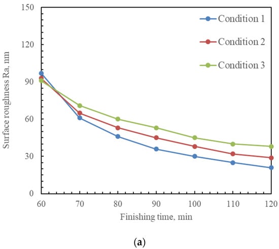
Figure 9.
Change in surface roughness Ra, Rz, and material removal M in the conditions with different working gaps after 60 min of precision finishing stage of MAF process. (a) Change in surface roughness Ra; (b) change in surface roughness Rz; (c) change in material removal M.
Figure 10 shows the change in surface roughness Ra, Rz, and material removal M in the conditions with different feeding speeds after 60 min of the precision finishing stage of the MAF process. With a slow feeding speed of the magnetic machining tool, there was enough machining time for the mixed magnetic abrasive particles detained on the inner surface of the curved tube. In other words, the polishing effect of the mixed magnetic abrasive particles was enough. Although the number of machining times was increased when the magnetic machining tool moved with a high feeding speed, the machining track of inner surface became sparse, probably causing the finishing quality of the inner surface to be uneven. Therefore, it is considered that the best surface quality was obtained in the condition of 20 mm/min feeding speed.
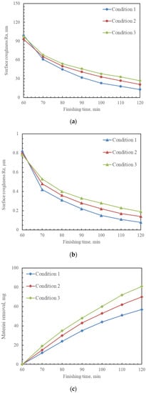
Figure 10.
Change in surface roughness Ra, Rz. and material removal M in the conditions with different feeding speeds after 60 min of precision finishing stage of MAF process. (a) Change in surface roughness Ra; (b) change in surface roughness Rz; (c) change in material removal M.
3.3. Multi-Stage MAF Process
3.3.1. Experimental Conditions
Finally, according to the above experimental investigations in two different machining stages, the experiments of the MAF process were performed in multiple stages with different combinations of the mixed magnetic abrasive. The detailed experimental conditions of multi-stage MAF process are shown in Table 9. The feeding speed of the external poles is set to 20 mm/min. The rotational speed of the external poles is 360 rpm. The working gap is 4 mm. The multi-stage MAF process is divided into four stages with different combinations of mixed magnetic abrasive. The total finishing time is 90 min, each finishing stage is 10 min. The total supply quantity of the mixed magnetic abrasive as shown in Table 10 is 0.4 g (Cond. 1), 0.6 g (Cond. 2), and 0.8 g (Cond. 3), respectively.
Table 9.
Experimental conditions of experiment 7 in multiple stages.
Table 10.
Experimental conditions of the mixed magnetic abrasive with different supply quantity.
3.3.2. Experimental Results
The change in surface roughness Ra and material removal M in the conditions of mixed magnetic abrasives with different supply quantities after 90 min of the multi-stage MAF process are shown in Figure 11. Experimental results showed that the surface roughness Ra and Rz in Cond. 2 was less than that in Cond. 1 and Cond. 3. The maximum material removal M was obtained in Cond. 1. It is considered that the mixed magnetic abrasive particles adsorbed on the magnet tool with a spontaneous stirring phenomenon when the supply quantity of the mixed magnetic abrasive was excessively injected into the curved tube. The excessive increase in the supply quantity of the mixed magnetic abrasives caused the decrease in the attraction of the external mixed magnetic abrasive particles pressed on the inner surface of the curved tube. Hence, the optimum supply quantity of the mixed magnetic abrasive grains was 0.4 g electrolytic iron powder and 0.2 g KMX magnetic abrasive particles in the multi-stage MAF process.
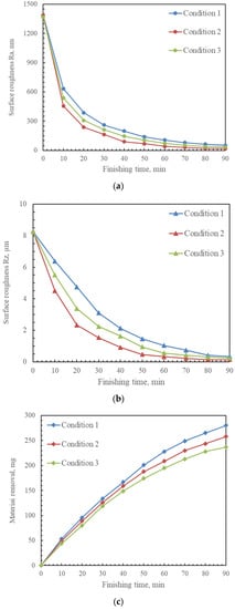
Figure 11.
Change in surface roughness Ra, Rz, and material removal M in the conditions of mixed magnetic abrasive with different supply quantity after 90 min of multi-stage MAF process. (a) Change in surface roughness Ra; (b) change in surface roughness Rz; (c) change in material removal M.
Figure 12 shows the metallographic images of the internal surface in the curved area before and after machining (×500). From the results, it was found that surface defects, such as pores, convex bodies, and pits existed on the original internal surface of workpiece. The surface defects were completely removed after the multi-stage MAF process, and it was observed that only the polishing trace with the same direction remained on the internal surface of the workpiece.
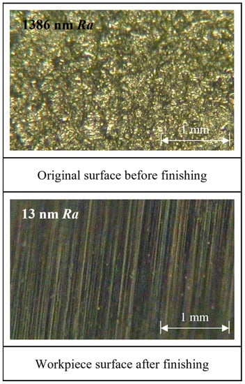
Figure 12.
Metallographic images of the internal surface in the curved area before and after machining (×500).
4. Discussion
The mixed magnetic abrasive particles arranged along the direction of the magnetic field force to form a magnetic brush. A single magnetic abrasive particle, respectively, generates force Fx, force Fy and force Fz along the direction of the magnetic field line. During the MAF process, the machining force in X, Y, Z directions and synthetic force F are calculated by Formulas (1)~(4).
where “K” is the correction coefficient, “D” is the diameter of the magnetic abrasive particle, “χ” is the susceptibility of the magnetic abrasive particle, “µ0” is the permeability of vacuum, “H” is the intensity of the magnetic field, and ∂H/∂x and ∂H/∂y are, respectively, the gradients of the magnetic field intensity in the x direction and y direction. Since the intensity of magnetic field “H” is proportional to machining force, it is considered that the intensity of magnetic field “H” is the main factor that affects the machining force. The intensity of magnetic field “H” can be calculated by Equation (5):
where “B” is the magnetic flux density and “µ” is the magnetic permeability of the medium. The magnetic flux density “B” is proportional to the intensity of the magnetic field “H”. Therefore, the magnetic flux density “B” is also considered the main factor that affects the machining force.
F2= Fx2 + Fy2 + Fz2
H = B/µ
The magnetic flux density cloud map and the magnetic field line distribution map in the MAF process without and with the internal magnetic tool were analyzed in Ansys Maxwell software and shown in Figure 13 and Figure 14. The maximum element size of the mesh was selected as 1 mm. The magnetic flux density near the inner surface of the workpiece in the MAF process without an internal magnetic machining tool, shown in Figure 13a, was approximately 0.17 T. The magnetic flux density near the inner surface of the workpiece in the MAF process with an internal magnetic machining tool, shown in Figure 13b, was approximately 0.53 T. By comparing the simulation results, it can be seen that in the MAF process with internal magnetic machining tools, the magnetic flux density near the inner surface of the workpiece is three times more than that of the MAF process without internal magnetic machining tools. Hence, it was regarded that a relatively strong magnetic flux density was generated by inserting internal machining tools into the curved tube in the MAF process.
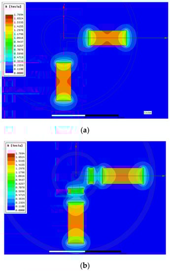
Figure 13.
Magnetic flux density cloud map in the MAF process without and with an internal magnetic tool. (a) Magnetic flux density cloud map in the MAF process without an internal magnetic tool; (b) magnetic flux density cloud map in the MAF process with an internal magnetic tool.
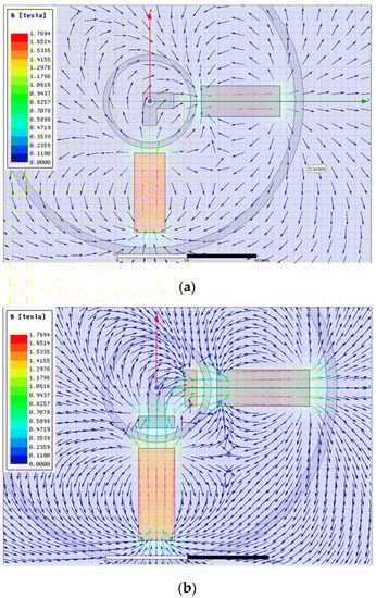
Figure 14.
Magnetic field line distribution map in the MAF process without and with an internal magnetic tool. (a) Magnetic field line distribution map in the MAF process without an internal magnetic tool; (b) magnetic field line distribution map in the MAF process with an internal magnetic tool.
By comparing the magnetic field line distribution maps in the MAF processes without and with internal magnetic tool, it is seen that the aggregation effect of the magnetic force lines was more obvious in the MAF process with the internal magnetic tool. In addition, it is also regarded that the magnetic field line distribution map near the inner surface of the workpiece in the MAF process with an internal magnetic machining tool was several times more than that near the inner surface of the workpiece in the MAF process without an internal magnetic machining tool. Thus, the magnetic machining force was increased in the MAF process when an internal magnetic machining tool was inserted into the curved tube.
5. Conclusions
This study proposed a new magnetic abrasive finishing (MAF) method, in which a 6-axis robot with a magnetic machining tool was used to polish the inner surface of curved tubes. The effect of the main machining parameters on the finishing characteristics was investigated in the initial machining stage and precision finishing stage. Based on investigating machining parameters, a multi-stage MAF process was performed to polish the inner surface of the curved tubes. The main conclusions are summarized as follows:
- A new magnetic abrasive finishing (MAF) method, which used a 6-axis robot with a magnetic machining tool, was proposed to polish the inner surface of the curved tube;
- Firstly, the total supply quantity of mixed magnetic abrasive, working gap, rotational speed, and combinations of abrasives with different particle sizes in the initial machining stage’s parameters were investigated by performing a series of comparative experiments in the initial machining stage;
- Then, the working gap and feeding speed were also investigated by performing a series of comparative experiments in the precision finishing stage;
- Based on the experimental investigations into two different machining stages, the experiments of the MAF process were performed in multiple stages. The optimal experimental results showed that the roughness Ra of inner surface reached 13 nm, from an original roughness value of 1630 nm in multiple stages of 105 min MAF process;
- The magnetic flux density cloud map and the magnetic field line distribution map in the MAF process without and with internal magnetic tool were analyzed in Ansys Maxwell software. By comparing the simulation results, it was revealed that a greater magnetic flux density and a better aggregation effect of the magnetic force lines were generated by inserting internal machining tools into the curved tube in the MAF process.
6. Patents
This section is not mandatory but may be added if there are patents resulting from the work reported in this manuscript.
Author Contributions
The first author, Z.Z., is responsible for writing this paper and analyzing the magnetic field of the magnetic machining tools. The corresponding author, X.S., his responsible for proposing the method, planning the experiments, and developing the experiments. Y.Y. is responsible for collecting and processing the data. Y.F. is responsible for performing the experiments. Y.Y. and Y.F. are also responsible for designing the magnetic machining tools and analyzing the magnetic field of the magnetic machining tools. Y.F. statistically analyzed and measured the works. All authors have read and agreed to the published version of the manuscript.
Funding
We declare the valuable contributions to and support for this study from Dr. Start Funding from Longyan University (LB2019002); the Huaqiao University Engineering Research Center of Brittle Materials Machining (MOE, 2020IME-003); Young Teachers’ Education Research Project of Fujian (JAT210448 & JAT220371); Natural Science Foundation of Fujian Province (2022J011148); Zhejiang Provincial Science and Technology Plan Project (2022C03121 & 2023C01162).
Institutional Review Board Statement
Not applicable.
Informed Consent Statement
Not applicable.
Data Availability Statement
The data is available on reasonable request from the corresponding author.
Acknowledgments
The part of this work was supported by Wencheng Xie from the Utsunomiya University Creative Department for Innovation (CDI).
Conflicts of Interest
The authors declare no conflict of interest.
References
- Kumar, C.G.; Anand, S.K. Significance of microbial biofilms in food industry: A review. Int. J. Food Microbiol. 1998, 42, 9–27. [Google Scholar] [CrossRef]
- Fisher, J.; Kaufmann, E.; Pense, A. Effect of Corrosion on Crack Development and Fatigue Life. Transp. Res. Rec. 1998, 1624, 110–117. [Google Scholar] [CrossRef]
- Hang, W.; Wei, L.Q.; Debela, T.T.; Chen, H.Y.; Zhou, L.B.; Yuan, J.L.; Ma, Y. Crystallographic orientation effect on the polishing behavior of LiTaO3 single crystal and its correlation with strain rate sensitivity. Ceram. Int. 2022, 48, 7766–7777. [Google Scholar] [CrossRef]
- Sun, X.; Zou, Y.H. Development of magnetic abrasive finishing combined with electrolytic process for finishing SUS304 stainless steel plane. Int. J. Adv. Manuf. Technol. 2017, 92, 3373–3384. [Google Scholar] [CrossRef]
- Yamaguchi, H.; Shinmura, T.; Sekine, M. Uniform Internal Finishing of SUS304 Stainless Steel Bent Tube Using a Magnetic Abrasive Finishing Process. J. Manuf. Sci. Eng. 2005, 127, 605–611. [Google Scholar] [CrossRef]
- Deng, Y.M.; Zhao, Y.G.; Zhao, G.Y.; Gao, Y.W.; Liu, G.X.; Wang, K. Study on magnetic abrasive finishing of the inner surface of Ni–Ti alloy cardiovascular stents tube. Int. J. Adv. Manuf. Technol. 2021, 118, 2299–2309. [Google Scholar] [CrossRef]
- Kang, J.; George, A.; Yamaguchi, H. High-speed internal finishing of capillary tubes by magnetic abrasive finishing. Procedia CIRP 2012, 1, 414–418. [Google Scholar] [CrossRef]
- Liu, J.N.; Zou, Y.H. Study on Mechanism of Roundness Improvement by the Internal Magnetic Abrasive Finishing Process Using Magnetic Machining Tool. Machines 2022, 9, 112. [Google Scholar] [CrossRef]
- Shinmura, T.; Takazawa, K.; Hatano, E. Study on magnetic abrasive finishing: Rounding condition and its confirmation by experiment. Bull. Jpn. Soc. Precis. Eng. 1986, 52, 1598–1603. (In Japanese) [Google Scholar] [CrossRef]
- Wang, Y.; Hu, D. Study on the inner surface finishing of tubing by magnetic abrasive finishing. Int. J. Mach. Tools Manuf. 2005, 45, 43–49. [Google Scholar] [CrossRef]
- Yan, B.H.; Chang, G.W.; Cheng, T.J.; Hsu, R.T. Electrolytic magnetic abrasive finishing. Int. J. Mach. Tools Manuf. 2003, 43, 1355–1366. [Google Scholar] [CrossRef]
- Zhang, S.R.; Yang, L.F.; Wu, G.X. Experimental Study on Increasing Magnetic Abrasive Finishing Efficiency of Finishing Nonferromagnetic Materials. Key Eng. Mater. 2007, 359, 300–304. [Google Scholar] [CrossRef]
- Yamaguchi, H.; Shinmura, T.; Ikeda, R. Study of Internal Finishing of Austenitic Stainless Steel Capillary Tubes by Magnetic Abrasive Finishing. J. Manuf. Sci. Eng. 2007, 129, 885–892. [Google Scholar] [CrossRef]
- Hitomi, Y.; Anil, K.S.; Michael, T.; Fukuo, H. Magnetic Abrasive Finishing of cutting tools for high-speed machining of titanium alloys. CIRP J. Manuf. Sci. Technol. 2014, 7, 299–304. [Google Scholar]
- Zou, Y.H.; Liu, J.N.; Shinmura, T. Study on Internal Magnetic Field Assisted Finishing Process Using a Magnetic Machining Jig for Thick Non-Ferromagnetic Tube. Adv. Mater. Res. 2011, 325, 530–535. [Google Scholar] [CrossRef]
- Yang, Y.Z.; Xue, Y.; Li, B.X.; Fu, Y.J.; Jiang, Y.H.; Chen, R.X.; Hang, W.; Sun, X. A Magnetic Abrasive Finishing Process with an Auxiliary Magnetic Machining Tool for the Internal Surface Finishing of a Thick-Walled Tube. Machines 2022, 10, 529. [Google Scholar] [CrossRef]
- Muhamad, M.R.; Zou, Y.H.; Sugiyama, H.S. Investigation of the finishing characteristics in an internal tube finishing process by magnetic abrasive finishing combined with electrolysis. Trans. IMF 2016, 94, 159–165. [Google Scholar] [CrossRef]
- Muhamad, M.R.; Jamaludin, M.F.; Ab Karim, M.S.; Yusof, F.; Zou, Y.H. Effects of electrolysis on magnetic abrasive finishing of AA6063-T1 tube internal surface using combination machining tool. Materialwiss. Werkst. 2018, 49, 442–452. [Google Scholar] [CrossRef]
- Ridha, M.M.; Zou, Y.H. Magnetic Abrasive Finishing of Internal Surface of Aluminum Pipe Using Magnetic Machining Jig. Adv. Mater. Res. 2014, 894, 222–226. [Google Scholar] [CrossRef]
- Wang, C.J.; Cheung, C.F.; Ho, L.T.; Yung, K.L.; Kong, L.B. A novel magnetic field-assisted mass polishing of freeform surfaces. J. Mater. Process. Technol. 2020, 279, 116552. [Google Scholar] [CrossRef]
- Wang, C.J.; Loh, Y.M.; Cheung, C.F.; Wang, S.X.; Ho, L.T.; Li, Z. Shape-adaptive magnetic field-assisted batch polishing of three-dimensional surfaces. Precis. Eng. 2022, 76, 261–283. [Google Scholar] [CrossRef]
- Singh, N.; Kumar, H.; Gill, J.S. Internal Finishing of Aluminium Tube with Sintered Magnetic Abrasive. Int. J. Eng. Appl. Sci. 2016, 3, 76–79. [Google Scholar]
- Han, B.; Liu, L.X.; Chen, Y. Optimization of Process Parameters for Magnetic Grinding Method to Process the Inner Surface of Pipe Bends. Chin. J. Mech. Eng. 2015, 26, 814–817. (In Chinese) [Google Scholar]


Disclaimer/Publisher’s Note: The statements, opinions and data contained in all publications are solely those of the individual author(s) and contributor(s) and not of MDPI and/or the editor(s). MDPI and/or the editor(s) disclaim responsibility for any injury to people or property resulting from any ideas, methods, instructions or products referred to in the content. |
© 2023 by the authors. Licensee MDPI, Basel, Switzerland. This article is an open access article distributed under the terms and conditions of the Creative Commons Attribution (CC BY) license (https://creativecommons.org/licenses/by/4.0/).