Abstract
Icing is a common phenomenon in nature and has a serious impact on wind turbines. Anti-icing coatings have become a major focus of industrial applications and academic research. In this study, a hydrophobic nano-carbon coating was prepared from corn-straw-biogas residue. The characterization results of the SEM, BET, FTIR, and XRD analyses showed that the hydrophobic nano-carbon has good pore structure and crystal structure. The hydrophobic and anti-icing effects of the carbon were confirmed by contact-angle measurements and anti-icing experiments. The ice thicknesses of the hydrophobic nano-carbon-coated aluminum-alloy blade (AAB) and bakelite blade (BB) were found to decrease by 1.20 mm and 1.10 mm, respectively, compared with those without coating; their weights decreased by 2.00 g and 1.31 g, respectively. The ratios of the icing areas before and after the hydrophobic nano-carbon coating of the AAB and BB were 8.15% and 9.65%, respectively. In brief, this method is a more effective technique for creating anti-icing coatings on wind-turbine blades and other outdoor apparatus.
1. Introduction
Natural energy resources are continuously reducing, since they are largely consumed in industry and our daily lives [1]. Wind energy, as a renewable energy source, has been found to have abundant reserves and promising development prospects [2,3]. Due to the high air densities and low population densities in cold marine environments, wind energy can often be used more efficiently [4]. However, in addition to the characteristics of marine environments, such as wind, waves, and currents, sea-ice hazards are significant factors to be considered in the design and operation of offshore wind farms in cold regions (such as the Baltic Sea, Bohai Bay, and Bothnian Bay) [5]. If ice is not removed from wind-turbine blades in a timely manner, this leads to a reduction in power output [6], thus limiting the performance of the wind turbine [7]. As a result, the use of anti-icing and de-icing technologies for wind turbines should be investigated to improve their efficiency [8]. Active and passive approaches are the two basic ways to lessen or eliminate the formation of ice on wind-turbine blades [9]. The active methods consist of thermal and mechanical methods. Active ice-protection systems consume a considerable amount of energy and are expensive to manufacture and operate [10]. In contrast, passive anti-icing methods (such as anti-icing coatings) are environmentally friendly and do not require external energy technologies, reducing the maintenance costs of wind-turbine equipment and preventing ice accumulation [11]. Thus far, passive anti-icing research has centered on the use of special coatings, particularly superhydrophobic nano-coatings. Based on recent advances in nanotechnology and material engineering, biomass nano-coating will become a multifunctional, intelligent, efficient, adaptive, and durable form of hydrophobic coating [12]. Lignocellulosic biomass, which is currently undervalued, is a common raw material for anaerobic digestion [13]. Improper disposal methods of biogas residue can lead to environmental pollution, while its resourceful use to prepare hydrophobic nanomaterials would benefit the development of anti-icing wind-turbine blades.
Superhydrophobic surfaces have been extensively researched in nature (e.g., lotus leaves and butterfly wings) [14]. Water droplets generate spherical droplets on superhydrophobic surfaces in general and minimize the surface area of contact between the solid and the water droplets. Droplets roll off superhydrophobic surfaces quickly if the tilting angle is sufficiently small; thus, the non-wettable property of these surfaces is good. Moreover, the pockets in the superhydrophobic surface’s micro/nano-scale hierarchical structure can operate as a thermal barrier, reducing the heat-transfer effect during the freezing process, thus significantly reducing the likelihood of ice adhesion [15,16]. Cui et al. proposed a new approach for fabricating superhydrophobic coatings using nano-SiO2 and a hydrophobic hyperbranched polymer as a binder [17]. Coatings made with this technology have higher adhesion strength and mechanical stability than those made using a hybrid procedure. Liu et al. reported a superhydrophobic surface created using spin coating and chemical-vapor-deposition processes from a nanocomposite based on nano-SiO2 particles and self-assembled monolayers of POTS [18]. The correlation between the properties and the hydrophobicity of the nanocomposites was examined. Thus, more approaches that are novel and simple for manufacturing hydrophobic nano-coatings on wind-turbine blades should be developed. To this end, numerous studies have been conducted to develop highly efficient hydrophobic carbon materials, including diamond [19], graphene [20], and carbon nanotubes (CNT) [21]. Eseev et al. studied a simple method proposed to obtain a superhydrophobic coating made from onion-like carbon nanoparticles manufactured with a low-cost, high-tech approach [22]. The developed relief of the onion-like carbon agglomerates was the physical reason for the appearance of the coating’s superhydrophobic properties, thus leading to the reproduction of the lotus effect. In short, carbon nano-materials have great application potential as excellent superhydrophobic materials.
Since superhydrophobic materials do not necessarily exhibit anti-ice properties, practical studies have focused on the supericephobicity properties of superhydrophobic materials. Zhang et al. applied molecular dynamics simulations to investigate the icephobicity of carbon surfaces functionalized with Na+, Cl+, or CH4 [23]. Valentini et al. reported that nanocomposites had an ice-phobic surface [24]. These researchers rationalized their results by observing the synergies between the expansion and nano-carbon phases in the composite’s ice-phobic properties. Thus, the nano-carbon materials exhibiting super-hydrophobic and super-icephobic properties were found to have good anti-icing effects. However, the application of these materials is limited because of their high synthesis costs. Compared with these carbon materials, biomass carbon has been reported as a promising hydrophobic material, since it is plentiful, reproducible, avirulent, and inexpensive compared with other carbon materials. Table 1 shows that using biogas residue as biomass carbon can shorten the time and reduce the cost. Table 2 lists the reduced contents of lignin, cellulose, and hemicellulose in corn stalks fermented with fermented cow manure as an inoculum, which contributes to the opening of spatial structures and helps obtain hydrophobic carbon materials with rough structures through annealing.

Table 1.
Comparison of reaction conditions for the preparation of carbon.

Table 2.
Chemical-composition comparison after fermentation.
In this study, a practical method for preparing hydrophobic carbon coatings on wind-turbine blades using rice-straw-biogas residue is proposed. The anti-icing mechanism of nano-carbon was analyzed, and the morphology and structure were investigated through FTIR, SEM, XRD, BET, and a video-based optical-contact-angle measuring instrument, to analyze the wetting characteristics. Moreover, the dynamic freezing adhesion, ice resistance, and change in mechanical characteristics of the adhesive force during the ice-layer pull-off failure of an icing blade coated with corn-straw-biogas-residue carbon with a hydrophobic coating were investigated through wind-tunnel experiments. In brief, the superhydrophobic nano-carbon coating of the corn-straw-biogas residue on the wind-turbine blade showed outstanding hydrophobic and anti-icing effects.
2. Materials and Methods
2.1. Materials
Commercial-grade polyvinylidene difluoride (PVDF, obtained from Harbin Lithium battery factory in China) was applied without additional treatment. The wind-turbine blade was a laboratory-made NACA0018 blade airfoil with chord length of 100 mm [33]. N-methyl pyrrolidone (NMP), and sulphuric acid (5%, Guangzhou Chemical Reagent Factory) were purchased from Tianjin Zhiyuan Chemical Reagent Co., Ltd. (Tianjin, China). Carbon in corn-straw-biogas residue was made from a small amount of cow dung as inoculum, using pure-cor- straw fermentation.
2.2. Fabrication of Biomas-Based Carbon Nano-Coating Blades
The first step was the preparation of biomass carbon. A pre-fermented cow dung inoculum was employed in the experiment to inoculate the pretreated water-immersed corn-straw fragments with 36 °C constant-temperature water-bath fermentation for twenty days. The solid was sifted and then dried to obtain dry corn-straw-biogas residue. The dried corn-straw-biogas residue was combined with 5% sulfuric acid before it was heated in the reaction kettle (HUASI Instrument Co., Ltd., Changsha, China) at 130 °C for 12 h. In the tube furnace (OTF-1200X, HF-kejing Material Technology Co., Ltd., Hefei, China), the carbonized product was heated to 400 °C for 0.5 h before it was heated to 800 °C for 1 h. The final product was corn-straw-biogas-residue nano-carbon.
Subsequently, superhydrophobic biomass-nano-carbon coating blades were fabricated. To make a homogeneous solution, 10 g PVDF was mixed with 133 g N-methyl pyrrolidone (NMP). Next, 56 mg biomass carbon was dispersed in 100 mg PVDF solution. After stirring under ultrasound for 4 h, the solution was applied to the wind-turbine blades using the scraping method. Lastly, the wind-turbine blades coated with nano-carbon were dried at 100 °C for 12 h, and then a porous superhydrophobic biomass carbon nano-coating was obtained on the wind-turbine blades. Figure 1 compares two blades before and after coating, and the coating thickness was 1.6 mm.
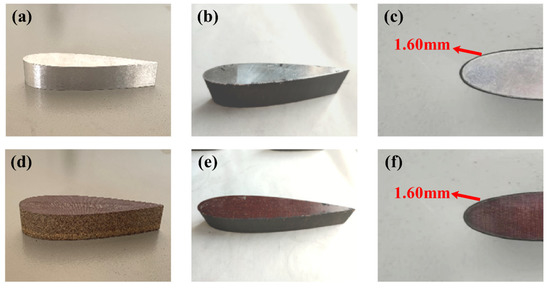
Figure 1.
(a) Uncoated AAB, (b,c) coated AAB, (d) uncoated bakelite alloy blade, (e,f) coated bakelite alloy blade.
2.3. Characterizations
In this study, the chemical compositions of biomass nano-carbon were investigated using FTIR (ALPHA-T, Brooke Germany Ltd., Ettlingen, Germany) for recording the spectra of the biomass nano-carbon. A D8 Advance Diffractometer was used to record XRD patterns (X’Pert Pro MPD, PANaiytical, Almelo, The Netherlands). The video-based optical-contact-angle measuring instrument (OCA20, Data Physics, Santa Clara, USA) was adopted to examine the hydrophobic properties of the coatings. The FESEM (S-4800, Hitachi, Tokyo, Japan) was adopted to characterize the morphology of the coatings. The BET (ASAP2460, Mike, Arlington, VT, USA) was used for the analysis of pore structure.
2.4. Anti-Icing Test
Anti-icing tests were conducted using an icing wind-tunnel system to perform dynamic icing tests. Figure 2 presents icing wind-tunnel system and test of live photos of blade models. The temperature range of the small icing wind-tunnel system was set to −20 °C–0 °C. The supercooled air sucked in by the wind tunnel was mixed with water mist, and the low-temperature water mist was sprayed onto the surface of the blade model by a water sprayer. The cross-section of the wind-tunnel-test section was a rectangle with dimensions of 250 mm × 200 mm. The outlet wind speed was 5 m/s, with an attack angle of 0 degrees on the blade airfoil.
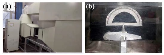
Figure 2.
(a) Icing wind-tunnel system and (b) Image of blade icing.
In this study, three values of experimental temperature were selected: 0 °C, −5 °C, and −10 °C. The experimental scheme and key experimental conditions are listed in Table 3.

Table 3.
Experimental scheme and conditions.
To investigate the effect of the change in the coating on the ice adhesion on the blade’s surface, the blade-surface ice adhesion was investigated. Figure 3 illustrates the experimental model of the adhesion test. The test model and blade corresponding to the blade shape were installed on the test bench. After the wind-tunnel-test device was started, refrigeration was performed at a wind speed of 5 m/s. At −20 °C, the spray system was opened, and the supercooled air was mixed with the water mist in the wind tunnel, thus affecting the surface of the supercooled blade model to form clear ice. The frozen model was separated from the blade by an electronic universal testing machine controlled using a microcomputer, the tensile curves of tangential force and normal force were generated, and the adhesion of ice on the blade was evaluated.

Figure 3.
(a) Experimental model of tangential force test, (b) experimental model of normal force test.
3. Results and Discussion
3.1. SEM Morphology
The morphology and microstructure of the corn straw and nano-carbon were analyzed under field-emission scanning-electron microscopy. Figure 4a,b illustrate the microstructure of the corn straw before and after the fermentation. According to Figure 4a, the cell wall of untreated corn straw was found to be smooth and flat, thus showing a clear texture. According to Figure 4b, compared with the fermented corn straw, the complex fiber structure was seriously damaged, with small and irregular holes on the surface of the corn straw, and secondary wall displacement of the fiber-cell wall occurred, forming a filament-broom shape, thus significantly decreasing the wrapping degree of the lignin to the cellulose and hemicellulose and making its structure looser, which could have contributed to the carbonization reaction.
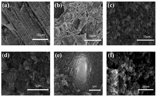
Figure 4.
The microstructure of corn straw (a) before and (b) after fermentation. (c–f) The microstructure of wind-turbine-blade surface with nano-carbon coating under different magnification levels.
Figure 4c–f illustrate the microstructure of the nano-carbon with different magnifications. As shown in Figure 4c,d, the nano-carbon material had a rich pore structure, and the aforementioned uneven dents and bumps formed a micro/nano-scale-roughness structure on the carbon surface, which increased the hydrophobicity. As indicated by the enlarged photograph in Figure 4e,f, this microstructure was an agglomeration of irregular carbon nanoparticles. The surface morphology of superhydrophobic nano-carbon coating’s hierarchical micro-nano structures approximated that of a lotus leaf [34,35].
3.2. FTIR Analysis
The chemical compositions of the nano-carbon were explored by using FTIR. Figure 5 illustrates the FTIR spectrum of the nano-carbon before and after annealing, as well as the characteristic absorption peaks. The absorption peak at 3443.9 cm−1 belonged to the stretching vibration of the O−H bonds in the cellulose and hemicellulose. During the annealing, small molecular functional groups (−OH, −COOH) were prone to dehydroxylation and decarboxylation reactions, producing small-molecule gas products, such as CO2, H2O, and CH4 (Equations (1) and (2)). Therefore, the −OH in the raw materials was mainly transferred to gaseous products in the form of small-molecule gas components. The surface micro-nano structure and the dehydroxylation and decarboxylation reactions of the nano-carbon increased and determined the surface hydrophobic properties of the materials. The C≡N−stretching vibration peaks of the nano-carbon were nearly 2350.3 cm−1, and the C−O−expansion vibration peak on the biomass carbon was 1095.5 cm−1, revealing that the surfaces of biochar made from cow dung and corn straw may have abundant functional groups.
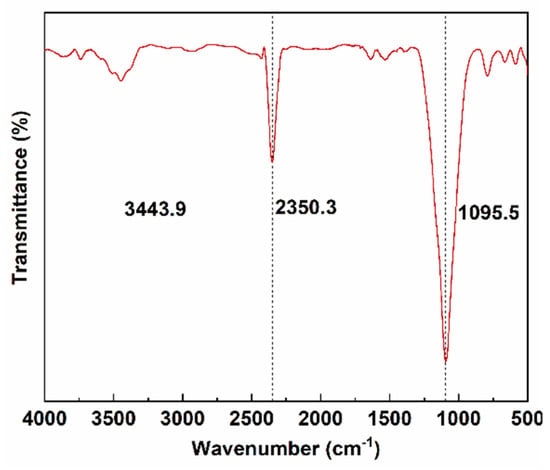
Figure 5.
FTIR spectra of nano-carbon.
3.3. XRD Analysis
The XRD patterns of the nano-carbon were obtained, as presented in Figure 6, to determine its crystal structure. The XRD pattern in Figure 6 contained a number of peaks in the region of 10°–70°, which were indexed as the diamond (111), graphite (002), (200), and (311) planes of C and C-N. The (002) planes represented the heat treatment at a high temperature, causing the partial graphitization of the material. As indicated by the higher back bottom, the sample contained a small amount of amorphous carbon [36]. These results revealed that the nano-carbon consisted of multiple components (e.g., diamonds and amorphous carbon).
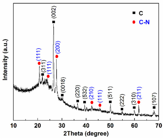
Figure 6.
XRD patterns of nano-carbon.
3.4. BET Analysis
The pore-size distribution was discovered to be the most important factor in the characterizing of the porous carbon. The N2 adsorption/desorption isotherms were used to determine the porous carbon’s structure. As shown in Figure 7a, the N2 adsorption–desorption isotherm was type III, indicating the existence of a multi-level pore structure on the hydrophobic surface of the nano-carbon. There were porous structures, as evidenced by the rapid increase in adsorption–desorption isotherms in the high-pressure region. The desorption isotherm deviated significantly from the adsorption isotherm, thus indicating that there were various pore structures, which was confirmed by the staggered porous structure presented by the SEM. The specific surface area of nano-carbon was 617.79 m2/g. According to Figure 7b, the pore size of the nano-carbon was primarily distributed between 10 nm and 100 nm. The porous carbon with larger pore sizes and pore volume was found to be similar to the uneven structure of a lotus leaf, in accordance with classical lotus leaf theory.
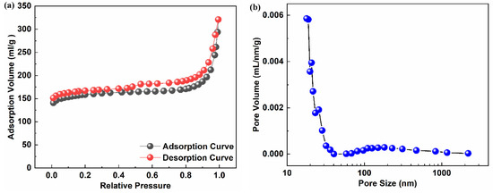
Figure 7.
(a) Nitrogen adsorption–desorption isotherm, (b) pore size distribution.
3.5. The Static Contact Angle Analysis
The hydrophobicity of the coating of the nano-carbon was evaluated by measuring the contact angle using a video-based optical-contact-angle meter. Figure 8a shows that the surface of the AAB was hydrophilic, with a water-contact angle of 32.3° before the coating. According to Figure 8b, the contact angle reached 151.05° after the nano-carbon coating. Figure 8c shows that the surface of the BB was hydrophilic, with a water-contact angle of 36.85° before the coating. According to Figure 8d, the contact angle reached 157.15° after the nano-carbon coating, and the hydrophobicity increased significantly. The droplets spread on the surface in the case in which no coating was applied. Theoretically, the air was stuck in those pores; thus, the rough nano-carbon coating could be viewed as a composite material composed of air and nano-carbon trapped in the pores, which can be modeled by Cassie-Baxter to describe [37]:
where the contact fractions of the water and the hydrophobic nano-carbon coating surface and water and air are designated as f1 and f2, and the equilibrium contact angle on the blank blade surface is expressed as θ.
cos θr = f1∙cos θ − f2
cos 151.05° = f1∙cos 32.3° − (1 − f1)
cos 157.15° = f1∙cos 36.85° − (1 − f1))
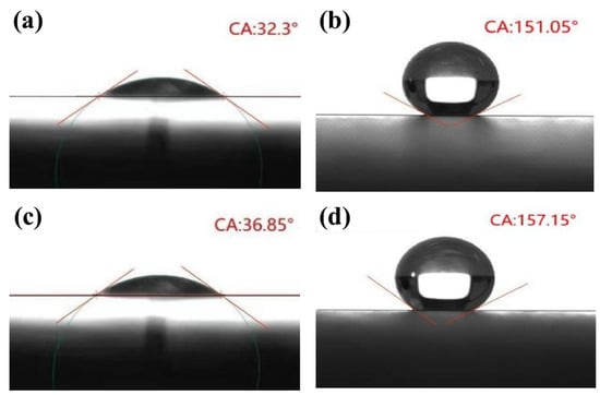
Figure 8.
(a) Contact angle of uncoated AAB, (b) contact angle of coated AAB, (c) contact angle of uncoated BB, (d) contact angle of coated BB.
As shown in Table 4, the f1 of the AAB coating obtained was nearly 6.78%, and the f1 of the BB coating was determined at about 4.33%. This showed that when the nano-carbon coating on the rough surfaces of the AAB and BB was in contact with the water droplets, the intercepted areas in the air were 93.22% and 95.67%, respectively. As revealed by the results, the water droplets were nearly spherical. When the supercooling water dropped on the superhydrophobic coating, it did not easily remain on the surface of the coating and rolled off the surface quickly before releasing its latent heat.

Table 4.
Contact angle and contact fraction of uncoated blade and coated blade.
3.6. Wind-Tunnel Dynamic Icing Test
To explore the anti-icing effect of the nano-carbon coating under the dynamic freezing conditions of the supercooled water droplets, the dynamic icing test was performed on the blade in the icing wind tunnel. Supercooled water droplets were sprayed on the blade. The analytical balance was adopted to weigh the two coating models every 10 s after the experiment began. At the same time, the ice patterns were recorded with a high-definition camera, after which the ice-weight differences, maximum thickness, and ice-area ratio were used to determine the icing differences between the two coating models.
3.6.1. Comparison of Ice-Weight Differences
The icing wind-tunnel test was repeated three times, and Table 5 shows the comparison of the one-minute icing quality of the AAB and BB under different wind speeds and experimental temperatures. It can be seen that the ice weight of the coated blades was much lower than that of the uncoated blades, which proved that the nano-carbon coating had a good anti-icing effect.

Table 5.
Blade’s icing weights under different experimental conditions.
Figure 9a,b present the change curve of the ice-coating weight on the coated and uncoated surfaces of AAB and BB in the static anti-icing experiment when the wind speed was 5 m/s and the test temperature was 0 °C. As clearly illustrated in Figure 9, the weight of the uncoated wind-turbine-blade model increased linearly, while the weight of the hydrophobic nano-carbon-coating-blade model also increased linearly; however, the increase was less than with the uncoated blade, and the growth trend of the BB was also less than that of the AAB. The maximum icing weights of the strong hydrophobic-nano-carbon-coating-based AAB and BB surfaces were almost 0.10 g and 0.09 g, respectively. The maximum icing weights of the uncoated blade were almost 2.10 g and 1.40 g, respectively. By comparing the ice types, the thickness of the ice on the surface of the blade coated with nano-carbon was lower.
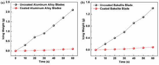
Figure 9.
Comparison results of icing change on (a) AAB and (b) BB surfaces on ice-proof wind-tunnel test.
3.6.2. Comparison of Maximum Icing Thicknesses
Through the ice-pattern images of the AAB and BB coating models after the icing and the highest results on the ice-proof wind-tunnel test, the ice thickness was measured at the point at which the front end of each of the four blade types was covered with the largest amount of ice. The overall icing images and the enlarged contrast images of local icing were obtained for the four types of blade. The main icing area of each blade was observed at the leading edge of the blade. According to Figure 10b,d, the uncoated AAB was 1.90 mm, and the nano-carbon-coated AAB was 0.70 mm. As indicated by Figure 10f,h, the uncoated BB was 1.60 mm, and the nano-carbon-coated BB was 0.50 mm. It was therefore revealed that the maximum icing thickness of the nano-carbon-coated BB was the lowest, which had a better anti-icing effect.
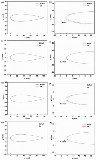
Figure 10.
(a,b) Uncoated AAB, (c,d) coated AAB, (e,f) uncoated BB, (g,h) coated BB.
3.6.3. Comparison of Ice-Area Ratio
Through the ice-pattern images of the AAB and BB coating models, using the Monte Carlo algorithm, the icy areas of the blades were calculated based on a binary morphology. The method used to choose the image for solving these areas was to compare the image of the icy blade on a small square background with a known area as a reference object and convert the post-icing blade information into computer-recognizable image information. Because the digital images were made up of pixels, the area of the blade after icing was calculated based on the pixel scale and the area of the reference object. The area-calculation result is shown in Figure 11. Figure 11a,c show the AAB’s surface ice area. Figure 11b,d show the BB’s surface ice area.
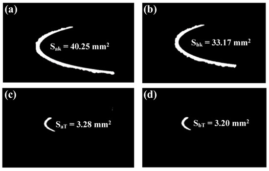
Figure 11.
(a,c) The AAB’s surface ice area. (b,d) The BB’s surface ice area.
We defined the ice-area ratio to compare the change in the ice area on the surface of the blade before and after coating. The ice-area ratio was defined as:
where is the AAB’s surface-ice-area ratio. Next, we performed a calculation according to the definition in Formula (6):
where is the BB’s surface-ice-area ratio. Next, we performed a calculation according to the definition in Formula (6):
From the comparative data, it was concluded that the ice area of the coated blade surface was significantly less than that of the uncoated blade surface, and that the ice-area ratio of the BB surface was slightly higher than that of the AA-coated blade surface. Therefore, when the surface of the AA was coated with the nano-carbon coating, the anti-icing effect was more obvious.
3.7. Test for Comparison of Blades’ Icing Adhesion
A microcomputer-controlled electronic universal testing machine was adopted to separate the frozen model from the blade, and the tensile curves of the tangential force and normal force were generated, as presented in Figure 12. The tangential force and the normal force tended to increase before and after coating, and the ice adhesion of the coated blades was less than that of the uncoated blades. As indicated by the figure, the coating was discovered to exert a significant impact by preventing the ice from adhering to the blade surfaces. As revealed by comparing the tangential force and the normal force of the two blade surfaces, the normal force on the blade was excessively small, probably due to the force direction and the ice-bonding area. Moreover, the tangential force and the normal force of the AAB were higher than those of the BB, thus indicating that the AA base equipment was easier to freeze, and that its anti-icing was more significant.
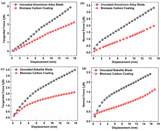
Figure 12.
(a) Tangential-force tensile curve of AAB before and after coating. (b) Normal-force tensile curve of blade before and after AAB coating. (c) Tangential-force tensile curve of BB before and after coating. (d) Normal-force tensile curve of BB before and after coating.
3.8. Anti-Icing Mechanism of Blade with Nano-Carbon Coating
As shown in Figure 13, the blade was placed horizontally, and the liquid water flowed through the blade surface, from left to right. Figure 13a illustrates the uncoated blade. Figure 13b illustrates the supercooled water dripping on the blade, after which considerable water droplets adhered to the blade surface and formed a large area of continuous wetting-water film on this surface, as presented in Figure 13c. Under low-temperature icing, the water film on the blade surface quickly formed an ice layer and bonded to the blade surface; thus, a strong icing state formed on the blade surface, as in Figure 13d. According to Figure 13e, after the blade (Figure 1a) was replaced with a blade with a nano-carbon coating (Figure 13e), it was difficult for the water droplets to wet the surface of the nano-carbon coating due to the super hydrophobicity of the nano-carbon, plentiful water droplets slid along the blade’s leading edge, and a few water droplets moistened the nano-carbon coating’s surface, as presented in Figure 13f, so it was found to be difficult to form ice. However, Figure 13g shows that over time, the water droplets increasingly gathered on the surface of nano-carbon coating and tended to form small-scale water films. These water films tended to form ice layers under the conditions of low-temperature icing, which were bonded to the blades’ surfaces, as presented in Figure 13h. The thickness and range of the ice layer on the blades’ surfaces significantly decreased. Accordingly, the nano-carbon coating delayed the icing time and reduced the icing of the blades’ surfaces.
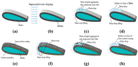
Figure 13.
(a) uncoated blade, (b) uncoated blade icing, (c) schematic diagram of water droplet aggregation on the uncoated blade, (d) schematic diagram of ice formation on the uncoated blade surface, (e) nano carbon coating blade, (f) nano carbon coating blade icing, (g) schematic diagram of water droplet aggregation on the nano carbon coating blade, (h) schematic diagram of ice formation on the nano carbon coating blade surface.
4. Conclusions
In this study, nano-carbon coatings were prepared from corn-straw-biogas residue, and the anti-icing performances of wind-turbine-coated blades were investigated.
(a) The water-contact angles of the strong hydrophobic nano-carbon-coated AAB and BB were measured as 151.05° and 157.15°, respectively.
(b) The maximum icing weights of the strong hydrophobic nano-carbon-coated AAB and BB in an artificial wind tunnel were found to be nearly 0.10 g and 0.09 g, respectively. The ratio of ice areas before and after the hydrophobic nano-carbon coating of the AAB and BB were 8.15% and 9.65%, respectively.
(c) The adhesion of ice to the coated blades ice was less than of the adhesion to the uncoated blades, which were easier to de-ice. The surface of the BB was also easier to de-ice than that of the AAB.
Author Contributions
Conceptualization, F.F. and Y.L.; methodology, F.F.; software, R.W. and W.Y.; formal analysis, W.Y.; data curation, R.W.; writing—original draft preparation, R.W.; writing—review and editing, F.F.; supervision, Y.L.; project administration, F.F.; funding acquisition, F.F. All authors have read and agreed to the published version of the manuscript.
Funding
Funding for the experiment was provided by project grant no. 20XG20, supported by the Fund of “Academic Backbone” of Northeast Agricultural University.
Institutional Review Board Statement
Not applicable.
Informed Consent Statement
Not applicable.
Data Availability Statement
Not applicable.
Conflicts of Interest
The authors declare no conflict of interest.
References
- Dalili, N.; Edrisy, A.; Carriveau, R. A review of surface engineering issues critical to wind turbine performance. Renew. Sustain. Energy Rev. 2009, 13, 428–438. [Google Scholar] [CrossRef]
- Zeng, J.; Song, B. Research on experiment and numerical simulation of ultrasonic de-icing for wind turbine blades. Renew. Energy 2017, 113, 706–712. [Google Scholar] [CrossRef]
- Mu, Z.Q.; Li, Y.; Guo, W.F.; Shen, H.; Tagawa, K. An experimental study on adhesion strength of offshore atmospheric icing on a wind turbine blade airfoil. Coatings 2023, 13, 164. [Google Scholar] [CrossRef]
- Jolin, N.; Bolduc, D.; Swytink-Binnema, N.; Rosso, G.; Godreau, C. Wind turbine blade ice accretion: A correlation with nacelle ice accretion. Cold Reg. Sci. Technol. 2019, 157, 235–241. [Google Scholar] [CrossRef]
- Ji, S.; Yang, D. Ice loads and ice-induced vibrations of offshore wind turbine based on coupled DEM-FEM simulations. Ocean Eng. 2022, 243, 110197. [Google Scholar] [CrossRef]
- Song, Z.; Liu, J.; Hu, Y.; Fang, F.; Yu, Z. Modeling and analysis of bottom fixed platform offshore wind turbine under ice loads. Proc. Chin. Soc. Electron. Eng. 2021, 41, 4144–4152. [Google Scholar]
- Ye, K.H.; Li, C.; Chen, F.D.; Xu, Z.F.; Zhang, W.F.; Zhang, J.W. Floating ice load reduction of offshore wind turbines by two approaches. Int. J. Struct. Stab. Dyn. 2018, 18, 31. [Google Scholar] [CrossRef]
- Xu, K.; Hu, J.L.; Jiang, X.L.; Meng, W.; Lan, B.H.; Shu, L.C. Anti-icing performance of hydrophobic silicone-acrylate resin coatings on wind blades. Coatings 2018, 8, 12. [Google Scholar] [CrossRef]
- Peng, C.; Xing, S.; Yuan, Z.; Xiao, J.; Wang, C.; Zeng, J. Preparation and anti-icing of superhydrophobic PVDF coating on a wind turbine blade. Appl. Surf. Sci. 2012, 259, 764–768. [Google Scholar] [CrossRef]
- Wei, K.X.; Yang, Y.; Zuo, H.Y.; Zhong, D.Q. A review on ice detection technology and ice elimination technology for wind turbine. Wind Energy 2020, 23, 433–457. [Google Scholar] [CrossRef]
- Li, C.; Li, X.H.; Tao, C.; Ren, L.X.; Zhao, Y.H.; Bai, S.; Yuan, X.Y. Amphiphilic antifogging/anti-icing coatings containing POSS-PDMAEMA-b-PSBMA. ACA Appl. Mater. Interfaces 2017, 9, 22959–22969. [Google Scholar] [CrossRef] [PubMed]
- Nguyen-Tri, P.; Tran, H.N.; Plamondon, C.O.; Tuduri, L.; Vo, D.-V.N.; Nanda, S.; Mishra, A.; Chao, H.-P.; Bajpai, A.K. Recent progress in the preparation, properties and applications of superhydrophobic nano-based coatings and surfaces: A review. Prog. Org. Coat. 2019, 132, 235–256. [Google Scholar] [CrossRef]
- Xu, X.; Sun, Y.; Sun, Y.; Li, Y. Bioaugmentation improves batch psychrophilic anaerobic co-digestion of cattle manure and corn straw. Bioresour. Technol. 2022, 343, 126118. [Google Scholar] [CrossRef] [PubMed]
- Wu, Y.; Zhao, M.; Guo, Z. Robust, heat-resistant and multifunctional superhydrophobic coating of carbon microflowers with molybdenum trioxide nanoparticles. J. Colloid Interface Sci. 2017, 506, 649–658. [Google Scholar] [CrossRef] [PubMed]
- Ruan, M.; Li, W.; Wang, B.S.; Deng, B.W.; Ma, F.M.; Yu, Z.L. Preparation and anti-icing behavior of superhydrophobic surfaces on aluminum alloy substrates. Langmuir 2013, 29, 8482–8491. [Google Scholar] [CrossRef]
- Latthe, S.S.; Sutar, R.S.; Bhosale, A.K.; Nagappan, S.; Ha, C.-S.; Sadasivuni, K.K.; Liu, S.; Xing, R. Recent developments in air-trapped superhydrophobic and liquid-infused slippery surfaces for anti-icing application. Prog. Org. Coat. 2019, 137, 105373. [Google Scholar] [CrossRef]
- Cui, H.; Hu, M.; Yu, Z.; Xiao, J. Preparation and characterization of a durable superhydrophobic hyperbranched poly(dimethylolbutanoic acid-glycidyl ester of versatic acid)/nano-SiO2 coating. Appl. Surf. Sci. 2019, 466, 171–178. [Google Scholar] [CrossRef]
- Liu, J.P.; Janjua, Z.A.; Roe, M.; Xu, F.; Turnbull, B.; Choi, K.S.; Hou, X.H. Super-hydrophobic/icephobic coatings based on silica nanoparticles modified by self-assembled monolayers. Nanomaterials 2016, 6, 232. [Google Scholar] [CrossRef]
- Montano-Figueroa, A.G.; Alcantar-Pena, J.J.; Tirado, P.; Abraham, A.; de Obaldia, E.; Auciello, O. Tailoring of polycrystalline diamond surfaces from hydrophilic to superhydrophobic via synergistic chemical plus micro-structuring processes. Carbon 2018, 139, 361–368. [Google Scholar] [CrossRef]
- Ding, S.; Xiang, T.; Li, C.; Zheng, S.; Wang, J.; Zhang, M.; Dong, C.; Chan, W. Fabrication of self-cleaning super-hydrophobic nickel/graphene hybrid film with improved corrosion resistance on mild steel. Mater. Des. 2017, 117, 280–288. [Google Scholar] [CrossRef]
- Stevens, K.A.; Esplin, C.D.; Davis, T.M.; Butterfield, D.J.; Ng, P.S.; Bowden, A.E.; Jensen, B.D.; Iverson, B.D. Superhydrophobic, carbon-infiltrated carbon nanotubes on Si and 316L stainless steel with tunable geometry. Appl. Phys. Lett. 2018, 112, 5. [Google Scholar] [CrossRef]
- Eseev, M.K.; Kapustin, S.N.; Lugvishchuk, D.S.; Mordkovich, V.Z.; Lyakh, N.L. A superhydrophobic coating based on onion-like carbon nanoparticles. Tech. Phys. Lett. 2020, 46, 1120–1123. [Google Scholar] [CrossRef]
- Zhang, X.X.; Chen, M. Icephobicity of functionalized graphene surfaces. J. Nanomater. 2016, 2016, 6731840. [Google Scholar] [CrossRef]
- Valentini, L.; Bittolo Bon, S.; Pugno, N.M.; Hernandez Santana, M.; Lopez-Manchado, M.A.; Giorgi, G. Synergistic icephobic behaviour of swollen nitrile butadiene rubber graphene and/or carbon nanotube composites. Compos. Part B Eng. 2019, 166, 352–360. [Google Scholar] [CrossRef]
- Liu, Z.; Sun, Y.; Xu, X.; Meng, X.; Qu, J.; Wang, Z.; Liu, C.; Qu, B. Preparation, characterization and application of activated carbon from corn cob by KOH activation for removal of Hg(II) from aqueous solution. Bioresour. Technol. 2020, 306, 123154. [Google Scholar] [CrossRef]
- Liu, C.; Li, N.; Peng, L.; Zhong, W.Z.; Mao, L.Q.; Yin, D.L. Hydrothermal carbonization of renewable natural plants as superior metal-free catalysts for aerobic oxidative coupling of amines to imines. ACS Sustain. Chem. Eng. 2020, 8, 11404–11412. [Google Scholar] [CrossRef]
- Liu, Z.Y.; Liu, Z.D. Comparison of hydrochar- and pyrochar-based solid acid catalysts from cornstalk: Physiochemical properties, catalytic activity and deactivation behavior. Bioresour. Technol. 2020, 297, 122477. [Google Scholar] [CrossRef]
- Xing, X.; Jiang, W.; Li, S.; Zhang, X.; Wang, W. Preparation and analysis of straw activated carbon synergetic catalyzed by ZnCl2-H3PO4 through hydrothermal carbonization combined with ultrasonic assisted immersion pyrolysis. Waste Manag. 2019, 89, 64–72. [Google Scholar] [CrossRef] [PubMed]
- Fan, L.P.; Fan, L.L.; Yu, T.; Tan, X.; Shi, Z.Q. Hydrothermal synthesis of lignin-based carbon microspheres as anode material for lithium-ion batteries. Int. J. Electrochem. Sci. 2020, 15, 1035–1043. [Google Scholar] [CrossRef]
- Ma, H.F.; Chen, Z.H.; Wang, X.D.; Liu, Z.B.; Liu, X.X. A simple route for hierarchically porous carbon derived from corn straw for supercapacitor application. J. Renew. Sustain. Energy 2019, 11, 7. [Google Scholar] [CrossRef]
- Zhang, Y.; Jiang, Q.; Xie, W.; Wang, Y.; Kang, J. Effects of temperature, time and acidity of hydrothermal carbonization on the hydrochar properties and nitrogen recovery from corn stover. Biomass Bioenergy 2019, 122, 175–182. [Google Scholar] [CrossRef]
- Xie, X.M.; Wang, Y.; Li, X.F.; Wei, X.S.; Yang, S. Pickering emulsions stabilized by amphiphilic carbonaceous materials derived from wheat straw. Colloid Surf. A-Physicochem. Eng. Asp. 2018, 558, 65–72. [Google Scholar] [CrossRef]
- Tong, G.; Li, Y.; Tagawa, K.; Feng, F. Effects of blade airfoil chord length and rotor diameter on aerodynamic performance of straight-bladed vertical axis wind turbines by numerical simulation. Energy 2023, 265, 126325. [Google Scholar] [CrossRef]
- Ensikat, H.J.; Ditsche-Kuru, P.; Neinhuis, C.; Barthlott, W. Superhydrophobicity in perfection: The outstanding properties of the lotus leaf. Beilstein J. Nanotechnol. 2011, 2, 152–161. [Google Scholar] [CrossRef]
- Gao, X.; Su, L.; Jiang, G.Q.; Pang, J.Y.; Lin, L. Dimensional stability of lotus leaf-like nanostructure superhydrophobic bamboo by modification using xylan. BioResources 2020, 15, 3443–3457. [Google Scholar] [CrossRef]
- Lu, L.; Huggins, T.; Jin, S.; Zuo, Y.; Ren, Z.J. Microbial metabolism and community structure in response to bioelectrochemically enhanced remediation of petroleum hydrocarbon-contaminated soil. Environ. Sci. Technol. 2014, 48, 4021–4029. [Google Scholar] [CrossRef] [PubMed]
- Liu, Z.; Feng, F.; Li, Y.; Sun, Y.; Tagawa, K. A corncob biochar-based superhydrophobic photothermal coating with micro-nano-porous rough-structure for ice-phobic properties. Surf. Coat. Technol. 2023, 457, 129299. [Google Scholar] [CrossRef]
Disclaimer/Publisher’s Note: The statements, opinions and data contained in all publications are solely those of the individual author(s) and contributor(s) and not of MDPI and/or the editor(s). MDPI and/or the editor(s) disclaim responsibility for any injury to people or property resulting from any ideas, methods, instructions or products referred to in the content. |
© 2023 by the authors. Licensee MDPI, Basel, Switzerland. This article is an open access article distributed under the terms and conditions of the Creative Commons Attribution (CC BY) license (https://creativecommons.org/licenses/by/4.0/).