Abstract
Steel is mainly produced through continuous casting; molten steel flows into the mold from the tundish, where it cools and then enters the secondary cooling zone, ultimately solidifying into a billet. During the continuous casting production process, the quality of the casting billet is mainly related to the lubrication state of the coated slag. In the upper part of the mold, the consumption of liquid protective slag directly affects the friction state of the initial solidified billet shell. Therefore, the flow and fluctuation characteristics of coated slag in the meniscus area are very important. There is limited research on the flow and fluctuation characteristics of coated slag in the meniscus area, and little consideration has been given to the shape of the meniscus. In this work, a two-dimensional numerical model for the flow and fluctuation of coated slag in the meniscus region was established, and the transient flow velocity of protective slag and molten steel at each moment of the vibration cycle was obtained, as well as the fluctuation of the slag/steel interface in the meniscus region. The results show that when the surface mold vibrated upwards, the protective slag in the meniscus area flowed clockwise. When the mold moved downwards, the protective slag in the slag pool generated a counterclockwise flow vortex. When the mold was in a positive slip state, the negative pressure formed by the upward flow of the protective slag on the meniscus and the inertia force of steel liquid pushed the meniscus toward the inner wall of the mold. During negative slip, the flow of coated slag generated positive pressure on the slag/steel interface, pushing the meniscus toward the steel liquid, and at the initial moment of negative slip, the steel liquid overflowed into the slag channel. This model could provide a theoretical basis for the flow control of protective slag.
1. Introduction
Continuous casting is an efficient means of steel production, and improving the yield of continuous casting billets is always the most crucial factor in the production process. The yield and defect of the casting billet at the meniscus of the continuous casting mold are closely related to the flow behavior of the initial solidified billet shell and the protective slag of molten steel in the meniscus region. Protective slag can improve the lubrication of the casting billet, reduce friction, reduce drawing resistance, and prevent bonding steel leakage. At the same time, it can control the heat exchange between the casting billet and the mold, improve the uniformity of heat transfer and improve the quality of the casting billet. The shape of the meniscus is mainly influenced by factors such as the interfacial tension between molten steel and the protective slag, the static pressure of molten steel, and the pressure generated by the flow of coated slag. The liquid protective slag above the meniscus area continuously flows into the gaps between the continuous casting of the shell and the mold wall due to the vibration and capillary phenomenon of the mold, forming a slag film and providing a lubrication effect. During this cycle, the inflow of protective slag is influenced by continuous casting process parameters. At the same time, the shape of the slag circle in the meniscus area also affects the inflow of protective slag. In continuous casting production, it is necessary to control the composition, physical parameters, and heat transfer performance of protective slag to control the formation and growth of the slag ring [1,2,3,4,5,6,7].
A large number of academicians have conducted studies on the heat exchange and flow of protective slag. Suzuki et al. [8] investigated the influence of sulfur in slag on the dynamic change in the liquid steel/slag interfacial tension; it should be noted that sulfur first existed in the coated slag but not in the molten steel. They calculated the apparent contact angle at the air/slag/steel triple interface using the floating lens method, which was affected by the balances among the surface tension of steel, the surface tension of slag and the interfacial tension between steel and slag in both horizontal and longitudinal directions. Yu et al. [9] developed a new type of the coated slag. The melting point and basicity of the slag was low. Three types of molten slags that were sampled after 8 min and 15 min were researched, and the chemical components of the coated slag composition and the performance of coated slag were calculated. According to the continuous casting test, the quality of the billet was good, without surface defects such as longitudinal face cracks and depression. The percentage composition of aluminum oxide in the coated slag pool increased with time in the initial phase and reached a state of balance after about 10 min. Meng et al. [10] built a 3D numerical model based on the finite-difference method; they considered the heat exchange between the mold and the billet. Stress and distortion were also calculated. The models were proved to be correct by comparing numerical models with the real data obtained from the steel plant. Considering the mechanical characteristics and time–temperature-transformation diagrams, the models were applied to study the effect of the casting speed and mold–powder viscosity properties on the slag-layer behavior between the oscillating mold wall and the solidifying steel shell. Yu et al. [11] conducted friction tests using a friction tester; therefore, the friction coefficient of crystalline slag and glassy slag could be obtained at different temperatures. A new type of oil was proposed to simulate the lubricated performance of liquid flux. These results show that during an increase in temperature from 25 degrees, the friction coefficient of slag increased because of surface softening. The surface sintering would apparently lower the friction coefficient of crystalline slag at a temperature of around eight hundred degrees. Solhed et al. [12] proposed a mathematical model for the tundish to reflect physical characteristics when molten steel was mixed with coated slag. Based on the calculated results, it was found that a circulation flowing in the entrance area was responsible for both the entrainment of steel drops into the slag and slag fragments into the steel. The highest concentration of slag in the steel was located at the region near the entrance, where flux debris dimensions were smaller because of a high degree of turbulent energy dissipation. Vdovin et al. [13] focused on the melting temperature of coated slag; they developed a new method to measure data at different temperatures. They showed the main items that affected experimental data through the differential scanning calorimetry method and operating conditions for these tests aimed at determining the liquefaction, melting, and slag spreading temperature.
Although scholars have conducted extensive research on protective slag, they mainly studied the heat exchange of coated slag. There has been limited research on the flow state of coated slag in the meniscus area, and little consideration has been given to the shape of the meniscus. This article establishes a two-dimensional numerical model for the flow of protective slag in the meniscus region and obtains the transient flow velocity of protective slag and molten steel at each moment of a vibration cycle, as well as the fluctuation of the slag/steel interface in the meniscus region. The calculation method and model proposed in this article could provide a theoretical basis and technical support for continuous casting production.
2. Model
The model consisted of a mold copper plate, protective slag, steel liquid, and an initially solidified billet shell. The calculation area of this article was taken at 45 mm above and below the top of the meniscus, and the distance from the mold to it was 20 mm, as shown in Figure 1. The VOF (Volume of Fluids) was used to track the wave of the liquid steel/slag interface around the meniscus region. Through calculating the Navier–Stokes formula for this model, the transient flow of protective slag in the meniscus region was simulated and calculated.
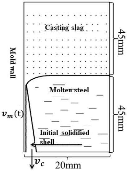
Figure 1.
Description of model domain in the meniscus region.
2.1. Governing Equation
2.1.1. VOF Equation
Due to the immiscibility of protective slag and molten steel, the VOF model was selected to solve the interface problem between the two phases. In any control unit, the sum of the volume fraction of molten steel and molten slag is one. Therefore, there were three possibilities within this unit.
- (1)
- = 1. The unit is filled with liquid slag, and there is no steel liquid present.
- (2)
- . The unit is a two-phase mixing zone.
- (3)
- = 0. The unit is filled with molten steel without any slag.
The tracing of the interface between these two phases was obtained by calculating the continuity equation for the volume fraction of a single phase. For protective slag , the equation is as follows [14]:
Here, is the velocity component, m/s. The calculation of the volume fraction of protective slag is based on the following constraints:
The density and viscosity of the fluid within the control unit are functions of the volume fraction, as shown in the following equation:
Here, and are the density of protective slag and molten steel, respectively, Kg/m3. and are the viscosity of protective slag and molten steel, respectively, Pa·s.
2.1.2. Continuity Equation
The continuity equation is the specific expression of the law for the conservation of mass in fluid mechanics [15].
Here, is a function of the volume fraction and density of each phase:
2.1.3. Momentum Equation
The momentum equation is a specific application of the momentum theorem in fluid mechanics, where the magnitude of the external force acting on an object is equal to the rate of change in the momentum of the object and the direction of force action [16].
Here, g represents the gravitational acceleration, m/s2. represents the power source term; it is a function of the interfacial tension between these two phases and the average density within the unit.
2.1.4. Turbulence Model
The flow model of protective slag needs to fully consider the impact of the mold vibration on the flow of protective slag, which requires high wall conditions. Therefore, the shear stress SST (Shear Stress Transmission) k-ω model was chosen.
The calculation equations for the turbulent pulsation kinetic energy k and the dissipation rate ω of turbulent pulsation kinetic energy are as follows [17]:
Here, is the generation coefficient of turbulent kinetic energy caused by the average velocity gradient. and are the effective diffusion terms:
Here, and are the turbulent Prandtl numbers. is the turbulent viscosity coefficient.
Here, S is the surface tension coefficient:
where F1 and F2 are the blending functions:
where y is the distance to the nearby surface, is the positive direction of the orthogonal divergence term:
2.1.5. Meniscus Contour Equation
The initial steady-state interface between the liquid slag and molten steel is given by the Bikerman equation [18]:
Here, x is the horizontal distance from the contact point of these two phases in the horizontal direction. y is the vertical distance from the highest point of the two adjacent contact surfaces. σ is the interfacial tension. g is the gravitational acceleration. is the density of molten steel. is the density of liquid slag.
2.2. Assumptions
- (1)
- The flowing steel and coated slag have a characteristic incompressibility, and they are steady-state flows.
- (2)
- The natural convection caused by density is ignored.
- (3)
- The calculation region of the model is small, while the thickness of the slag film and the initial shell remain unchanged.
- (4)
- The flow of molten steel in the meniscus area is mainly influenced by the casting speed and the flow of protective slag.
- (5)
- The gap between the casting billet and the mold is full of liquid slag; the flow velocity of liquid slag perpendicular to the drawing direction is ignored.
2.3. Boundary Condition
- (1)
- Upper surface of protective slag: a pressure inlet boundary with a pressure value of 1 atm.
- (2)
- Gap outlet: a pressure outlet boundary with a pressure value of 1 atm.
- (3)
- Mold wall: sinusoidal vibration.
- (4)
- Initial solidification shell: moves at the casting speed.
- (5)
- Right boundary of the model: no-slip boundary, with an isotropic velocity of 0; it is set as a symmetric boundary.
The calculated parameters are listed in Table 1.

Table 1.
The parameters of the model.
2.4. Calculation Method
The transient flow process of protective slag and molten steel can be calculated in two steps:
Step 1: Regardless of the movement of the mold and initial shell, the Bikerman equation is used to determine the initial interface between the protective slag and the molten steel, and the VOF model is selected to tail the movement of the steel/slag interface until it reaches a stable state.
Step 2: With the vibration of the mold and the downward movement of the initial solidification shell, the periodic flow of the protective slag is calculated; only a few vibration cycles are needed to perform the calculation.
3. Results and Discussion
3.1. Transient Flow Characteristics of Protective Slag during A Vibration Cycle
Corresponding velocities were applied to the mold wall and initial solidification shell to obtain the velocity vector maps for the transient flow of protective slag and molten steel at various times during a vibration cycle. Figure 2 shows the velocity and displacement curves of the mold, including vibration velocity, displacement, and pulling velocity. When t = 0 s, the mold was in an equilibrium position and moved upward at a maximum speed. When t = T/4 (0.100 s), the mold reached its highest position, and from this moment on, the mold began to move downward. When the downward vibration speed of the mold was greater than the pulling speed, it entered a negative slip state. The duration of the negative slip was 0.126–0.274 s while it was in a positive slip state at other times. The positive and negative slip parameters had a significant impact on the flow gap of protective slag, the consumption of protective slag and the formation of vibration marks. The following mainly discusses the flow pattern of protective slag and the influencing factors of protective slag consumption considering three aspects: the transient flow of protective slag in the meniscus area, the inflow and outflow status of protective slag in the slag channel, and the influence of vibration parameters on the consumption of protective slag. The calculation results in this article are consistent with those of Ramirez-Lopez et al. [19], Meng et al. [20] and Zhu et al. [21].
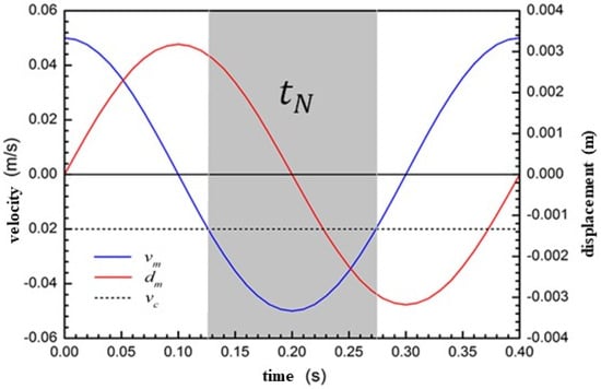
Figure 2.
Velocity, position and casting speed during an oscillation cycle.
Figure 3a–h show the velocity vector diagram of the transient flow of protective slag in the meniscus area during a vibration cycle. The red arrow represents the protective slag, and the blue arrow represents molten steel. The characteristics of the flow of protective slag and molten steel at different times within a vibration cycle were analyzed as follows:
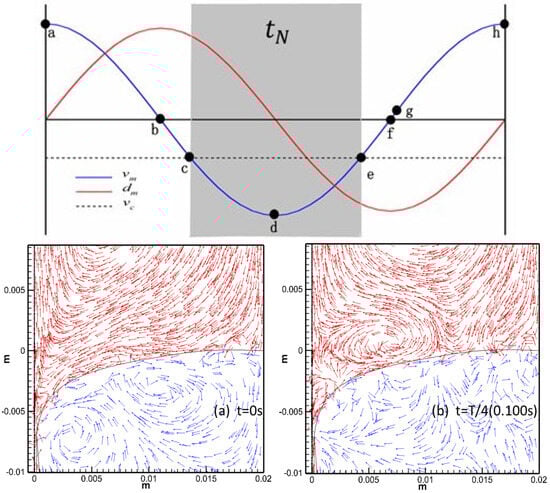
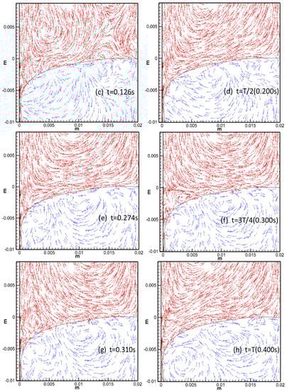
Figure 3.
Velocity vectors of liquid slag in the meniscus domain during one oscillation cycle.
(a) At the initial moment of periodic vibration t = 0 s, due to the upward vibration of the mold at its maximum speed, the relative movement speed between the mold and the casting billet reached its maximum value, and the protective slag in the meniscus area formed a clockwise flow vortex. At the same time, under the action of the upward movement of the mold, some protective slag flowed out of the gap in the slag channel.
(b) When t = T/4 (0.100 s), the mold reaches its highest position with a speed of 0. The protective slag in the gap between the mold wall and the billet underwent backflow. As the upward vibration speed of the mold decreased, the relative velocity between the casting billet and the mold decreased. The meniscus of protective slag flowed into the slag channel, and some protective slag flowed into the slag channel with the downward movement of the casting billet.
(c) At the initial moment of negative slip, t = 0.126 s, the mold vibrated downward. At the entrance to the slag channel, the flow of protective slag was divided into two streams. One stream generated a counterclockwise flow vortex, and the other stream flowed directly into the gap between the mold and the initial shell near the mold wall. It can be seen that when the downward movement speed of the mold was greater than the pulling speed due to the suction effect, the protective slag continued to flow into the gap.
(d) At T/2 (0.200 s), the mold returned to the equilibrium position and the downward vibration speed reached its maximum value. The downward vibration speed of the mold continuously increased, driving more protective slag to flow into the gap. It is beneficial to increase the flow rate of protective slag in the slag channel and increase the consumption of protective slag.
(e) At t = 0.274 s, the negative slip state ended and the protective slag continued to flow into the slag channel. Afterward, the speed at which the billet moved downward was greater than the downward vibration speed of the mold.
(f) At the moment of t = 3T/4, the mold reached its lowest point with a velocity of 0, and the protective slag in the meniscus area continued to flow counterclockwise due to inertia.
(g,h) The mold continued to move upward, causing the meniscus protective slag to generate a clockwise flow vortex, driving the protective slag to flow out of the gap. Within each vibration cycle, the flow state of the protective slag was consistent.
During each vibration cycle, the flow state of the protective slag alternated and repeated continuously.
Based on the above analysis, the flow state of protective slag was mainly influenced by the vibration law of the mold and the casting speed. When the mold vibrates upward, it drives the protective slag in the meniscus area to flow clockwise; however, when the mold vibrates downward, the protective slag in the calculation area flows counterclockwise. In the early stage of the positive slip and the final stage of the next positive slip, the protective slag in the slag channel generated reflux, which was not conducive to the consumption of protective slag. During the negative slip period, driven by the downward movement of the mold, protective slag continuously flowed into the slag channel.
3.2. Periodic Fluctuation Characteristics of the Meniscus
The slag/steel interface fluctuated with the flow of protective slag and steel liquid. When the volume fraction of protective slag was 0.5, it was considered as the slag/steel interface. The fluctuation of the meniscus during a vibration cycle is shown in Figure 4a–h. When the liquid slag flowed toward the slag/steel interface, positive pressure was generated on the interface; however, when the liquid slag moved away from the interface, negative pressure was generated on the interface.
Figure 4.
The behavior of the meniscus motion during one oscillation cycle.
(a,b) During the positive slip period, the protective slag in the meniscus area generated a clockwise flow vortex, and the negative pressure formed by the upward flow of the protective slag on the meniscus and the inertia force of steel continuously pulled the meniscus toward the inner wall of the mold.
(c) At t = 0.126 s, it was the beginning stage of negative slip, where steel liquid overflowed into the slag channel, and the inertia force of the steel flow continued to push the meniscus closer to the mold wall.
(d,e) The downward vibration speed of the mold was greater than the pulling speed, and the downward flow of the protective slag increased the positive pressure on the meniscus. The meniscus was pushed toward the steel liquid due to the positive pressure formed by the flow of the protective slag, and this stage continued until the end of the negative slip state.
(f) At the moment of 3T/4, the mold reached its highest position with a speed of 0. At this point, the flow of protective slag at the meniscus decreased with the decrease in mold vibration speed. Under the action of protective slag flow and molten steel flow, the meniscus approached the direction of the mold wall again.
(g,h) The mold vibrated from the lowest point upward, with a continuous increase in velocity. The protective slag in the meniscus area flowed clockwise, and the flow velocity increased with an increase in the mold vibration velocity, generating negative pressure on the meniscus and driving it continuously toward the inner wall of the mold.
The alternating flow vortices of protective slag during a vibration cycle exhibited a periodic change in positive/negative pressure on the meniscus. When in a positive slip state, the negative pressure, formed by the upward flow of the protective slag on the meniscus and the inertia force of the steel liquid, pushed the meniscus toward the inner wall of the mold. During the negative slip period, the flowing coated slag generated positive pressure on the slag–steel interface, pushing the meniscus toward the flowing steel. The seasonal fluctuation behavior of the meniscus was the root cause of the formation of vibration marks and solidification hooks on the seeming of the casting slab.
4. Conclusions
By calculating a two-dimensional numerical model for the flow and fluctuation of coated slag in the meniscus region, the transient flow velocity of protective slag and molten steel at each moment of the vibration cycle, as well as the wave of the slag/steel interface in the meniscus region, were obtained. The specific conclusions are as follows:
- (1)
- When the mold vibrated upward, the protective slag in the meniscus area flowed clockwise. When the mold moved downward, the protective slag in the slag pool generated a counterclockwise flow vortex.
- (2)
- At t = 0 s, the mold was in an equilibrium position and moved upwards at maximum speed. When t = T/4 (0.100 s), the mold reached its highest position, and from this moment on, the mold began to move downward. The duration of the negative slip was 0.126–0.274 s, while it exhibited a positive slip state at other times. The positive and negative slip parameters had a significant impact on the flow gap of protective slag, the consumption of protective slag and the formation of vibration marks.
- (3)
- When the mold was in a positive slip state, the negative pressure formed by the upward flow of the protective slag on the meniscus and the inertia force of the steel liquid pushed the meniscus toward the inner wall of the mold. During negative slip, the flow of protective slag generated a positive pressure on the slag/steel interface, pushing the meniscus toward the molten steel, and at the initial moment of negative slip, molten steel overflowed into the slag channel.
- (4)
- When the liquid slag flowed toward the slag/steel interface, positive pressure was generated on the interface; when the liquid slag moved away from the interface, negative pressure was generated on the interface.
Author Contributions
Data curation, Y.Z., S.W. and G.Z.; Writing—original draft, F.D. All authors have read and agreed to the published version of the manuscript.
Funding
This research received no external funding.
Institutional Review Board Statement
Not applicable.
Informed Consent Statement
Not applicable.
Data Availability Statement
Not applicable.
Conflicts of Interest
The authors declare no conflict of interest.
Nomenclature
| Item | Explanation |
| αst | volume fraction of molten steel |
| αsl | volume fraction of molten slag |
| velocity component | |
| t | time |
| ρ | density |
| μ | viscosity |
| k | turbulent pulsation kinetic energy |
| generation coefficients | |
| effective diffusion term | |
| σ | turbulent Prandtl numbers |
| S | surface tension coefficient |
| F | blending functions |
| positive direction of the orthogonal divergence term |
References
- Yang, J.; Wang, L.J.; Li, Y.; Wang, T.J.; Kong, L.Z.; Zhang, X.M. Modeling of Flux Reaction and Mixing in Continuous Casting Mold of Medium Mn Steel. Metal. Mater. Trans. B 2022, 53, 1516–1525. [Google Scholar] [CrossRef]
- Dozhdikov, V.I.; Cherkasov, N.V.; Vasyutin, A.Y.; Ganul, A.O. Simulation of the Heat-Transfer Conditions in a CCM Mold. Metallurgist 2022, 66, 610–616. [Google Scholar] [CrossRef]
- Furumai, K.; Aramaki, N.; Oikawa, K. Influence of heat flux different between wide and narrow face in continuous casting mould on unevenness of hypo-peritectic steel solidification at off-corner. Ironmak. Steelmak. 2022, 49, 845–859. [Google Scholar] [CrossRef]
- Han, F.N.; Wen, G.H.; Zhang, F.; Wang, Z.; Yu, L. Effect of Microstructure on the Granule Strength of Hollow Granulated Mold Fluxes for Continuous Casting. Steel Res. Int. 2023, 94, 2200480. [Google Scholar] [CrossRef]
- Neelakantan, V.N.; Sridhar, S.; Mills, K.C.; Sichen, D. Mathematical model to simulate the temperature and composition distribution inside the flux layer of a continuous casting mould. Scand. J. Metall. 2002, 31, 191–200. [Google Scholar] [CrossRef]
- Xu, L.; Pei, Q.W.; Han, Z.F.; Wang, E.A.; Wang, J.Y.; Karcher, C. Modeling study of EMBr effects on molten steel flow, heat transfer and solidification in a continuous casting mold. Metall. Res. Technol. 2023, 120, 218. [Google Scholar] [CrossRef]
- Swain, A.N.S.S.; Ganguly, S.; Sengupta, A.; Chacko, E.Z.; Dhakate, S.; Pandey, P.K. Investigation of corner cracks in continuous casting billet using thermomechanical model and plant measurements. Met. Mater. Int. 2022, 28, 2434–2447. [Google Scholar] [CrossRef]
- Suzuki, M.; Nakamoto, M.; Tanaka, T.; Tsukaguchi, Y.; Mishima, K.; Hanao, M. Effect of sulfur in slag on dynamic change behavior of liquid iron/molten slag interfacial tension. ISIJ Int. 2020, 60, 2332–2338. [Google Scholar] [CrossRef]
- Yu, X.; Wen, G.H.; Tang, P.; Ma, F.J.; Wang, H. Behavior of mold slag used for 20mn23al nonmagnetic steel during casting. J. Iron Steel Res. Int. 2011, 18, 20–25. [Google Scholar] [CrossRef]
- Meng, Y.A.; Thomas, B.G. Modeling transient slag-layer phenomena in the shell/mold gap in continuous casting of steel. MMTB 2003, 34, 707–725. [Google Scholar] [CrossRef]
- Yu, S.; Long, M.J.; Liu, P.; Chen, D.F.; Duan, H.M.; Yang, J. Experimental simulation on the high-temperature friction property of slag in slab continuous casting mold. J. Mater. Res. Technol. 2020, 9, 6453–6463. [Google Scholar] [CrossRef]
- Solhed, H.; Jonsson, L.; Jonsson, P. Modelling of the steel/slag interface in a continuous casting tundish. Steel Res. Int. 2008, 79, 348–357. [Google Scholar] [CrossRef]
- Vdovin, K.N.; Ryakhov, A.A.; Pivovarova, K.G.; Tochilkin, V.V. Features determining the melting temperature of slag-forming mixtures for steel continuous casting. Refract. Ind. Ceram. 2019, 60, 214–218. [Google Scholar] [CrossRef]
- Li, L.M.; Liu, Z.Q.; Cao, M.X.; Li, B.K. Large eddy simulation of bubbly flow and slag layer behavior in ladle with discrete phase model (DPM)-volume of fluid (VOF) coupled model. JOM 2015, 67, 1459–1467. [Google Scholar] [CrossRef]
- Zhang, X.W.; Jin, X.L.; Wang, Y.; Deng, K.; Ren, Z.M. Comparison of standard k-ε model and RSM on three dimensional tur-bulent flow in the SEN of slab continuous caster controlled by slide gate. ISIJ Int. 2011, 51, 581–587. [Google Scholar] [CrossRef][Green Version]
- Brackbill, J.U.; Kothe, D.B.; Zemach, C. A continuum method for modeling surface tension. J. Comput. Phys. 1992, 100, 335–354. [Google Scholar] [CrossRef]
- Menter, F.R. Two-equation eddy-viscosity turbulence models for engineering applications. Aiaa J. 1994, 32, 1598–1605. [Google Scholar] [CrossRef]
- Bikerman. Phisical Surfaces; Acadamic Press: London, UK, 1970. [Google Scholar]
- Ramirez-Lopez, P.E.; Lee, P.D.; Mills, K.C. Explicit modelling of slag infiltration and shell formation during mould oscillation in continuous casting. ISIJ Int. 2010, 50, 425–434. [Google Scholar] [CrossRef]
- Meng, X.N.; Zhu, M.Y. Analysis of liquid flux consumption mechanism for slab continuous casting mold with high casting speed. Acta Metall. Sin. 2009, 45, 485–489. [Google Scholar] [CrossRef]
- Zhu, L.G.; Jin, S.T. Numerical calculation on the flowing behaviour of mold fluxes between mold and shell. J. Iron Steel Res. 1998, 10, 9–12. [Google Scholar] [CrossRef]
Disclaimer/Publisher’s Note: The statements, opinions and data contained in all publications are solely those of the individual author(s) and contributor(s) and not of MDPI and/or the editor(s). MDPI and/or the editor(s) disclaim responsibility for any injury to people or property resulting from any ideas, methods, instructions or products referred to in the content. |
© 2023 by the authors. Licensee MDPI, Basel, Switzerland. This article is an open access article distributed under the terms and conditions of the Creative Commons Attribution (CC BY) license (https://creativecommons.org/licenses/by/4.0/).