Article

Quantitative Characterization of the Interfacial Damage in EB-PVD Thermal Barrier Coating

1
Aero Engine Academy of China, Aero Engine (Group) Corporation of China, Beijing 101304, China
2
Institute for Aero Engine, Tsinghua University, Beijing 100084, China
3
Sichuan Gas Turbine Establishment, Aero Engine (Group) Corporation of China, Chengdu 610500, China
4
Joint Research Center for Extreme Environment and Protection Technology, Xi’an Jiaotong University, Xi’an 710049, China
*
Author to whom correspondence should be addressed.
Coatings 2022, 12(7), 984; https://doi.org/10.3390/coatings12070984
Submission received: 10 June 2022 / Revised: 7 July 2022 / Accepted: 10 July 2022 / Published: 12 July 2022
(This article belongs to the Special Issue Corrosion, Cracks, and Failure of Advanced Thermal Barrier Coatings)

Abstract

:
Considering the influence of non-equibiaxial stress state and initial residual strain on the compressive buckling of the ceramic layer, a quantitative characterization method of the damage generated at the interface between the top coat and bond coat in thermal barrier coating based on uniaxial compression was developed. It was verified by the axial compression tests of the single crystal specimens with EB-PVD thermal barrier coating after undergoing various isothermal oxidation times and thermal cycles. On this basis, the correlations between the measured interfacial damage and the thermal loads experienced as well as the thickness of thermally grown oxide (TGO) were analyzed. The results show that the critical compressive strain inducing the spallation of thermal barrier coating at room temperature can effectively characterize the accumulation of interfacial damage caused by isothermal oxidation and thermal fatigue. Under the same TGO thickness, the damage caused by thermal fatigue is greater than that caused by isothermal oxidation. The total damage generated in thermal barrier coating can be divided into three parts: oxidatively driven damage related to TGO thickness, mechanically driven damage related to stress–strain cycles in the coating, and their interaction, where the interaction term is negative.

1. Introduction

As an effective high-temperature protective technology, thermal barrier coatings (TBC) have been widely used in aero engines and gas turbines to protect the turbine blades, vanes, combustors, and nozzles from the hot gas stream by providing thermal insulation up to about 170 °C [1]. TBC can improve the overall performance and thermal efficiency of engines by allowing higher gas temperatures or a reduced cooling airflow at a given metal temperature, and/or extend the service life of components by reducing the metal temperature at a given cooling airflow [2,3,4,5,6].
A thermal barrier coating system including a ceramic top coat (TC), a metallic bond coat (BC), and a superalloy substrate is shown in Figure 1, which the TC is yttria-stabilized zirconia (YSZ) ceramic layer with low thermal conductivity and good high-temperature stability as heat insulation between the hot gas and the substrate superalloy. The BC, such as MCrAlY (M = Ni and/or Co) or PtAl, etc., is introduced to relieve the thermal expansion mismatch and to prevent oxidation corrosion of the underlying superalloy substrate. In the high-temperature environment, Al cation in the BC reacts with the oxygen passing through the TC to form a thin thermally grown oxide (TGO) at the ceramic–metal interface, which can prevent the further penetration of oxygen. Meanwhile, TGO is detrimental to the mechanical compatibility inside the coating system because its thermal expansion coefficient is much smaller than the adjacent TC and BC. Therefore, TGO would cause the TBC to spall when it grows to a critical thickness [7,8,9,10,11,12].
According to the fabrication processes of ceramic layers, TBC can be divided into air plasma spraying (APS) [13] and electron beam physical vapor deposited (EB-PVD) [14]. As shown in Figure 1, the ceramic layer of APS has a lamellar structure with high porosity and good heat insulation and is mainly used for high-temperature static structures such as turbine guide vanes, combustion chambers, and tail nozzles. The ceramic layer fabrication by the EB-PVD process has a good strain tolerance due to the “feathery” and columned micro-structure, which can effectively relieve the tensile stress in the ceramic layer at high temperature. EB-PVD TBC is mainly used in the case of extreme thermal–mechanical coupling loadings such as turbine blades.
Although the number and the severity of TBC applications have dramatically increased in the past few decades, premature spallation failure of TBC during service is still the overriding concern for both academic and engineering communities [15]. Once the TBC spallation occurred, the underlying substrate superalloy would be exposed to a high-temperature aggressive environment exceeding the design capacity of the material, which could result in overheating or fracture of the structure, seriously jeopardizing the safety, reliability, and economy of the engine. Accurate prediction of the service life of TBC to fully exploit their performance advantages and potential is essential to the development of prime reliant coatings and hot section component design, as well as to engine life management.
Damage refers to the deterioration of the mechanical properties caused by the initiation and propagation of microcracks in a material, also representing the degree of consumption of the service life of the material or structure. It has been experimentally shown that the damage of TBC is characterized by nonlinear accumulation, which is significantly different from that of conventional metallic materials, and the classical Miner linear damage accumulation theory is no longer applicable [16]. For TBC deposited by the EB-PVD process, the damage is concentrated in the interfacial region between the YSZ and the BC. The growth and coalescence of microcracks at the YSZ–TGO interface, at the TGO–BC interface, or in the TGO are the specific manifestations of damage accumulation [15]. The characterization of interfacial microcracks using optical and acoustic non-destructive testing methods is straightforward for TBC damage measurement.
Due to the differences in the thermal expansion coefficients of different layers of materials in TBC, the TGO is subjected to large in-plane biaxial compressive stresses during cooling, which reaches extreme values (−3 to −6 GPa) at room temperature [8], and the local fracturing of TGO or separation at the YSZ–TGO interface or TGO–BC interface causes the relaxation of the residual stress induced in TGO. Based on this principle, Nychka [17], Selcuk [18], Tolpygo [19], Sridharan [20], Wen [21], Lee [22], Busso [23], Rinaldi [24], and Manero [25] estimated the TGO residual stress by using the photostimulated luminescence piezo-spectroscopy (PLPS) technique to determine the R-line fluorescence frequency shift generated by the excitation of Cr3+ impurities in TGO and correlated the fluorescence spectral parameters or the average TGO stress evolution with the TBC interfacial damage. However, because of the TGO growth and rumpling, the PLPS-measured parameters relating to damage in the above methods show a complex nonmonotonic variation with the number of thermal cycles [18,21,25], which is inconsistent with the monotonically increasing process of damage accumulation.
The microscopic fracture process in the TBC is accompanied by the release of elastic stress waves, i.e., acoustic emission (AE). Based on the AE signal history of the coating during the loading process in conjunction with spectral analysis, Renusch [26] and Yang [27] proposed that parameters such as the cumulative AE signal energy, number of events, and amplitude could be used to evaluating the TBC damage. Due to the incremental nature of the cumulative AE signal, this method can describe the growth of damage under thermal and mechanical loads well. However, AE signals are susceptible to interference from many types of phenomena such as the opening and closing of adjacent YSZ columnar as well as the inelastic deformation of the substrate and BC [28,29,30,31].
From a mechanics point of view, the interfacial damage of the TBC actually causes a decrease in the bond strength (also known as the interface toughness, interface adhesion, or spalling resistance) between the YSZ and the BC, which provides a new approach for the measurement of interfacial damage in the coatings. Kim [32] and Song [33] tested the evolution of the interfacial bond strength of a TBC after different cyclic thermal loads using the pull-out method and preliminarily confirmed the feasibility of quantifying the interfacial damage accumulation by the decrease in the bond strength. However, the test results showed that the pull-out method caused the fracture of YSZ itself [32,33], and the obtained bond strength could not accurately characterize the mechanical properties at the “interface” between the YSZ and the BC, leading to additional errors in the evaluation of the interfacial damage.
The macroscopic spallation of a TBC occurs mainly during cooling and is essentially a buckling failure caused by in-plane compressive stress in the YSZ [8]. Courcier [34] and Remy [35] simplified the TBC spalling to an elastic buckling problem of a thin plate and characterized the interfacial bond strength with the critical strain, inducing the spallation of TBC under axial compression at room temperature. Compared with the traditional pull-out method, this compressive buckling method achieves the correlation between the macroscopic TBC spallation and the microscopic interfacial damage and is closer to representing the mechanism of the TBC failure. However, there are still a series of problems that should be addressed. For example, the uniaxial compression test of the TBC does not satisfy the assumption of circular blister buckling [36,37], the effect of the initial residual stress in the YSZ is not considered in the calculation [7], and the visually determined critical strain for the compression spalling of the coating may not be reliable enough [31].
In view of the above problems, this study took an EB-PVD TBC as the research object to investigate the feasibility of evaluating the interfacial damage in the coatings by the critical compressive strain inducing the TBC spallation at room temperature. Through theoretical analysis combined with high precision non-contact optical measurement, quantitative characterization of the interfacial damage based on the uniaxial compression testing was further developed and experimentally verified to obtain the evolution of the TBC damage under different loading conditions and to provide basic data for damage mechanism analysis and lifetime modeling of TBC.

2. Quantitative Characterization of Interfacial Damage in TBC

The spallation process of the EB-PVD TBC can be generally divided into four stages [8,34,38], as shown in Figure 2I microcracks initiate and propagate at the interface under the combined action of stress and strain cycles in the coating, and the growth of TGO; Figure 2II adjacent microcracks gradually coalesce, causing interfacial delamination, i.e., the YSZ and the BC layer debond locally; Figure 2III when the interfacial delamination reaches a certain size, the debonded YSZ which may be accompanied by TGO buckles from the BC under the compressive thermal mismatch stress, which specifically manifests as the occurrence of “blisters” [39], and (IV) as the delamination size or compressive stress further increases, the buckling zone destabilizes and expands, leading to large spallation of the coating, or the brittle fractures of the YSZ due to excessive bending deformation [36,37]. The compressive thermal mismatch stress to which the YSZ and the TGO are subjected gradually increases with the decreasing temperature, which is the main reason that TBC spallation frequently occurs during cooling [40,41]. To obtain conservative results for the engineering design, the buckling of the YSZ is used as an indicator of TBC failure. Considering that the thickness of the coating, (i.e., the out-of-plane dimension) is much smaller than the in-plane dimensions and that the coating is mainly subjected to in-plane stress and strain during service, the TBC spallation can be simplified to an elastic buckling problem of a thin plate in compression.
To solve the above buckling problem, Courcier et al. [34] first introduced the concept of an “equivalent delaminated area” at the ceramic–metal interface, i.e., it is assumed that the microcracks including defects at the interface are mechanically equivalent to a circular surface crack with the normal in the out-of-plane direction. In this way, the locally debonded YSZ can be considered to be a circular plate prone to buckling, as shown in Figure 3a. When subjected to thermal mismatch stress, the YSZ is approximately in an in-plane equibiaxial stress state. Therefore, the critical compressive stress Equation (1) of the classical circular blister buckling [34,42] can be used to describe the buckling of the YSZ in compression.
σ c r i t = 1.2235   E 1 1 υ 1 2 ( h R ) 2
where σ c r i t   is the critical compressive stress (taken as its absolute value) as the ceramic layer begins to bulk, E 1 and ν 1   are the in-plane elastic modulus and Poisson’s ratio of the ceramic layer, respectively; h is the thickness of the ceramic layer, and R is the radius of the circular equivalent delaminated area. The pattern and number of microcracks generated at the coating interface vary with loading conditions, i.e., R is related to the loading history.
Since the interfacial bond strength of the coating depends on the effective bearing area at the ceramic–metal interface, Courcier [34] defined the interfacial damage D as the percentage increase in the area of the equivalent delaminated area at the current time relative to the initial area in the as-deposited TBC, the functional relationship between the critical compressive stress and the interfacial damage can be obtained as follows [34]:
σ c r i t = 1.2235   E 1 1 υ 1 2 ( h R ) 2 ( 1 D )
According to Equation (2), a gradually increasing compressive loading can be applied to the coating to activate the buckling of the YSZ to measure the critical compressive stress σ c r i t , thereby enabling the quantification of interfacial damage [34]. It should be noted that σ c r i t is the stress in the equibiaxial stress state. However, in most of the previous studies, the axial compression tests of the coated specimens were conducted, and the uniaxial stresses were considered as σ c r i t [31,34,35,43,44]. Due to the Poisson’s ratio of the substrate, the coating is subjected to axial compression and transverse tension, and hence, the equibiaxial stress state assumed by the above circular blister buckling is no longer valid. In addition, the test results indicate that, in addition to circular blister buckling [35,39,41,45], the coating may exhibit a phenomenon similar to straight-sided blister buckling at certain locations, (e.g., the edges) of the specimen [46,47,48,49,50,51].
For straight-sided blister buckling, assuming that the equivalent delaminated area is a rectangular surface crack with a length much larger than the width (denoted as 2b), the locally debonded YSZ can be considered to be a long and narrow plate that is prone to buckling with long sides subjected to uniform compressive stress, and the critical compressive stress for buckling [42] is
σ c r i t = π 2   12 E 1 1 υ 1 2 ( h R ) 2
In fact, the buckling mode of the TBC is between circular blister buckling and straight-sided blister buckling. Comparing Equations (1) and (3), it is assumed that the critical compressive stress for the coating buckling satisfies the following equation
σ c r i t = 1.2235 E 1 h 2 1 υ 1 2 α l 2
where α is a coefficient associated with the buckling mode and l is the characteristic size of the equivalent delamination area. α = 1 and l = R for circular blister buckling, α = 0.67225 and l = b for straight-sided blister buckling.
As mentioned earlier, the interfacial damage is closely related to the decrease in the spalling resistance between the YSZ and the BC. Hence, the interfacial damage is directly defined in this study as the percentage decrease in the spalling resistance in the current state relative to the initial spalling resistance in the as-deposited TBC:
D = σ c r i t , 0 σ c r i t σ c r i t = 1 l 0 2 / α 0 l 2 / α
Considering that the coating is mainly subjected to in-plane stress in the XY plane and is approximately in a plane stress state, the compressive stress σ y acting on the YSZ is determined by the constitutive relationship as
σ y = E 1 1 υ 1 2 ( ν 1 ε x + ε y )
In the axial compression test as shown in Figure 4, the strain of the YSZ is composed of two parts: the initial residual compressive strain of the YSZ, ε R [43,44], which is equal in all in-plane directions and caused by the coating preparation process, and the strain generated by the externally applied mechanical loading [31,34,35]. Under an applied axial compressive strain of ε A , the strain of the YSZ is determined as follows according to the deformation compatibility between the substrate and the coating [36]:
ε x = ε R ν s ε A     ε y = ε R + ε A
where ν s is the Poisson’s ratio of the substrate. According to Equations (6)–(10), the interfacial damage can be expressed as:
D = 1 ( 1 + ν 1 ) ε R + ( 1 ν 1 ν s ) ε c r i t A , 0 ( 1 + ν 1 ) ε R + ( 1 ν 1 ν s ) ε c r i t A , 0
where ε c r i t A is the critical compressive strain applied on the TBC when buckling occurs and ε c r i t A , 0 is the critical compressive strain corresponding to the as-deposited coating. As seen in Equation (8), the interfacial damage equation does not explicitly include α or l , that is, there is no direct correlation between the calculated interfacial damage and the adopted buckling mode assumption.
When the interfacial damage reaches a certain value D s p a l l , ε c r i t A is 0, and the YSZ buckles under its residual strain ε R :
D s p a l l = 1 ( 1 + ν 1 ) ε R ( 1 + ν 1 ) ε R + ( 1 ν 1 ν s ) ε c r i t A , 0
The above equation indicates that the coating will spall spontaneously the next time it is cooled to room temperature and can be used to determine whether the remaining life of the TBC has been exhausted. Due to the influence of the initial residual strain introduced in the calculation, the interfacial damage threshold corresponding to TBC spallation D s p a l l in this study is less than 1, which is different from those in other damage theories [26,34,52,53,54]. The initial residual strain ε R is the average value in the thickness direction of the YSZ and can be estimated by the thermal expansion mismatch strain in Equation (10) [52] or measured by synchrotron X-ray diffraction [55].
ε R = [ α s ( T p r o ) α 1 ( T p r o ) ] ( T p r o T r e f )
where α s ( T p r o ) and α 1 ( T p r o ) are the thermal expansion coefficients of the substrate and YSZ at temperature T p r o , respectively; T p r o is the initial stress-free temperature of the TBC system, which is usually taken as the coating deposition temperature; and T r e f is the temperature at which the coating compression testing is performed, which is generally room temperature. The above equations provide the theoretical basis for the quantitative characterization of the interfacial damage of TBC.

3. Tests and Measurements

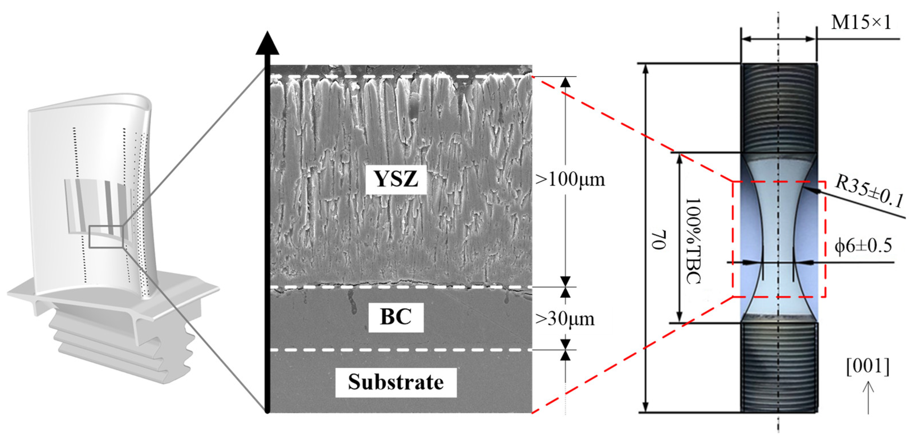
3.1. Materials and Specimens

Based on the method mentioned above, the axial compression tests of the nickel-based single crystal superalloy PWA1484 specimens with EB-PVD TBC after undergoing various thermal loads were performed to measure the interfacial damage evolution. As shown in Figure 5, EB-PVD TBC was deposited on the second-generation nickel-based single crystal superalloy PWA1484, whose composition is shown in Table 1. The crystallographic orientations of specimens are determined by the X-ray Laue back-reflection technique and the maximum deviation of the rod axis within 10° of orientation deviation to the main axis direction [001] were selected as the qualified products. After wet sandblasting with corundum particles with a diameter between 100 μm and 125 μm under 0.2 MPa air, cleaning, and drying, the bonding coat with the composition of NiCrAlYSi, as shown in Table 2, is deposited by the EB-PVD process with a thickness of not less than 30 μm. After the single crystal specimens with BC were subjected to vacuum heat treatment at 1000 °C for 4 h, they were shot-peened using glass pills with a diameter between 150 μm and 300 μm under the 0.3 MPa air, and then heat-treated at 1000 °C for 2 h in a vacuum. Then, following the same cleaning process, the TC of 8YSZ (8% Y2O3 + ZrO2) with a thickness of not less than 100 μm is deposited by the EB-PVD process in the laboratory of high-temperature structural materials and coating technology of Beihang University.

3.2. Test Schemas and Instruments

The schemas of the experiments performed on the specimens with EB-PVD TBC and the quantitative characterization of damage in TBC is shown in Figure 6. Firstly, through the QSX1600 muffle furnace, the isothermal oxidation test was carried out under 1050 °C, and the thermal fatigue test was performed with a maximum temperature of 1050 °C, as shown in Figure 7a. Note that each cycle included heating for 10 min followed by air cooling for 10 min, as shown in Figure 7b.
After experiencing specific oxidation hours or thermal cycles, the specimens with EB-PVD TBC were removed and cooled to room temperature and then conducted the compression test at room temperature using an MTS809 testing machine to investigate the toughness of interfacial between the ceramic and the metal. To compare the interfacial damage under thermal loadings, the thickness of TGO was obtained by SEM.

3.3. Measurements and Determination of the Critical Compressive Strain

The critical compressive strain of the TBC is a key parameter for the measurement of interfacial damage, and there are two major challenges to accurately determining it. One is the extraction of the coating surface strain. Extensometers have been used in most previous studies to record the macroscopic strain history of specimens within the gauge distance [29,34,35]. Since the stiffness of the substrate is much higher than that of the coating, the compression loading is mostly taken by the substrate, and the randomness in the orientation and mechanical properties of single crystal superalloy cause errors in the critical compressive strain measurement of the TBC. In addition, for the hourglass specimens used in this study, the coating buckling occurs locally, and the extensometer fails to achieve the fine measurement of local strain. Strain gauges would lead to changes in the stiffness of the YSZ and affect the spalling process and hence are also not applicable. The second challenge is to determine the onset of TBC spalling. At present, visual inspection or a charge-coupled device (CCD) camera is commonly used, and the presence of obvious “blisters” and fracture of the coating is taken as the criterion. The above theoretical analysis shows that ε c r i t A essentially corresponds to the onset of buckling of the YSZ when the out-of-plane displacement is not yet obvious. The critical compressive strain obtained by the conventional methods is random and faces difficulties in meeting the accuracy requirement of interfacial damage quantification.
To address the above problems, this study introduces the digital image correlation (DIC) method for real-time, noncontact, full-field dynamic strain measurement of the compression spalling of coatings. The principle of DIC testing is performed with the following specific steps, as shown in Figure 8I speckles are sprayed on the TBC-coated specimen to mark the locations of different points on the surface, and the internal parameters of the two cameras are calibrated; Figure 8II the motion of the speckles is recorded in real time with the calibrated cameras during the specimen compression, and Figure 8III based on the principle of computer stereo vision, speckle image sequences from the same time and different viewing angles are used to determine the displacement and strain of the coating surface using an image matching algorithm [56].
The DIC testing results showed that a horizontal or inclined surface strain concentration zone appeared in the middle of the specimen before the macroscopic spallation of the TBC that was basically consistent with the final spallation zone. There was a significant abrupt change in the slope of the surface compressive strain in this zone (Figure 9), and the time that the abrupt change occurred was consistent with that of the strain concentration zone (163 s). Considering that the displacement loading rate of the testing machine remained constant, the abrupt change in the surface compressive strain could be attributed to two factors: the incompatible deformation of the YSZ and the substrate, i.e., buckling and “blistering”, or the plastic deformation caused by the activation of the slip system of the single crystal superalloy substrate.
After the substrate entered the plastic regime, its resistance to deformation decreased, i.e., the slope of the compression–time curve of the specimen decreased, as shown in Figure 9, corresponding to a time of 187 s. The above results indicated that the substrate remained elastic for a period of time after the abrupt change in the slope of the surface compressive strain of the coating. Therefore, this study used the abrupt change in the slope of the surface compressive strain as the criterion for the onset of coating spalling, and the maximum absolute compressive strain corresponding to this time was extracted in the spallation zone as the critical compressive strain of the coating ( ε c r i t A ).
Since the surface compressive strain at each point in the spallation zone generally exhibited a bilinear pattern, we adopted the following approach to extract the strain: A piecewise linear fitting was performed on the surface compressive strain evolution curve for the spallation zone, then the intersection of the two fitted straight lines was taken as the critical point at which the coating started to buckle, and the corresponding strain was ε c r i t A . Additionally, ε c r i t A was taken as 0 for the specimens that TBC spalled spontaneously as shown in Figure 10.
TGO thickness is another key parameter that needs to be measured. In this study, SEM and image processing were combined to identify the TGO profile based on the difference in the grayscales of the boundaries of the top coat, TGO, and BC layer in the SEM image [19,57,58]. The difference between the ordinates of the upper and lower boundaries of the profile was used as the TGO thickness. At least 100 TGO thickness measurement points were considered for each specimen, as shown in Figure 11.

4. Analysis and Discussion

The evolution of the measured critical compressive strain for the TBC spallation is shown in Figure 12. ε c r i t A showed a decreasing trend with increasing isothermal oxidation time t and number of thermal cycles N , indicating that the interfacial bond strength decreased progressively under the action of TGO growth as well as the stress and strain cycles in the TBC. Based on the above results, the interfacial damage was calculated using Equations (8)–(10), with the relevant parameters in Table 3.
Figure 13 shows that the coating interfacial damage D t produced by the isothermal oxidation experiments exhibited a power-law relationship with the oxidation time t with a damage equation exponent of 2.17539, indicating that the damage rate increased gradually with the oxidation time. For the thermal fatigue experiments, there was an approximately linear relationship between the interfacial damage D N and the number of thermal cycles N , and the damage rate remained basically constant.
The evolution of the TGO thickness also exhibited a power-law trend (Figure 14), and the exponent of the TGO thickness growth curve was basically the same under the two test conditions. In the thermal fatigue experiments, the approximate hot time at 1050 °C for one cycle was 1/6 h. It was found that the regression curve of the TGO thickness for the thermal fatigue test basically coincided with the isothermal oxidation result, indicating that the stress–strain cycles in the coating caused by thermal fatigue did not significantly change the growth of the TGO thickness. Therefore, we selected the TGO thickness as a benchmark to comparatively analyze the interfacial damage generated under different thermal conditions in a unified coordinate system.
The correlation between interfacial damage and TGO thickness is shown in Figure 15. The two exhibited a power-law relationship in both isothermal oxidation and thermal fatigue experiments. With the same TGO thickness, the damage caused by the thermal fatigue was greater than that by the isothermal oxidation, indicating that thermal fatigue caused additional damage, which was mechanically driven and caused by the stress–strain cycles in the coating. This additional damage is denoted as D c y c in this study. The damage caused by the TGO growth was oxidatively driven and is denoted as oxidative damage D o x . Since the isothermal oxidation experiments involved only one thermal cycle, the mechanically driven damage generated was considered negligible, so D t D o x .
Considering the coupling oxidative–mechanical effect, it is assumed that the total damage generated at the coating interface in the thermal fatigue experiments accumulates according to the following relationship:
D N = D o x + D c y c + k D o x D c y c
where k is a coefficient that characterizes the interaction between oxidatively driven damage and mechanically driven damage. When k = 0 , the two damage components accumulate linearly with no interaction; when k < 0 , the total damage at the interface is less than the sum of the oxidatively driven damage and mechanically driven damage; when k > 0 , the oxidatively driven damage and mechanically driven damage are coupled to generate more damage. Without loss of generality, k is assumed to be 0, −1 and 1 herein, respectively, to explore the effect of k on the mechanically driven damage of TBC.
Using Equation (11), the interfacial damage induced by thermal fatigue is decoupled, as shown in Figure 16. In particular, the oxidatively driven damage has a power-law relationship with the TGO thickness, and the damage rate increases gradually with the oxidation time, while the evolution of the mechanically driven damage is closely related to value of the coefficient k . With k = 0 and k = 1 , the calculated D c y c first increases and then decreases, and the peak of the damage corresponds to a TGO thickness of approximately 2.1 μm, while with k = 1 , D c y c increases continuously with increasing TGO thickness. From a thermodynamic perspective, the interfacial damage in the coating is an irreversible process of increasing entropy, and D c y c should not decrease as the TGO thickness or the number of thermal cycles increases. In addition, a decrease in D c y c implies the abnormal healing of interfacial microcracks, which has not been revealed by the available results from the thermal fatigue test of the coating. Therefore, there should be a negative interaction between oxidatively driven damage and mechanically driven damage. One possible explanation is the evolution of the interface morphology [45,59] as shown in Figure 17. Under thermal fatigue loading, as the TGO thickness increases, the original relatively flat TGO gradually distorts and rumples, and the rumpling of the TGO simultaneously releases part of its stored elastic strain energy [20], causing a redistribution of stresses near the interface and thereby slowing the damage accumulation to some extent.

5. Conclusions

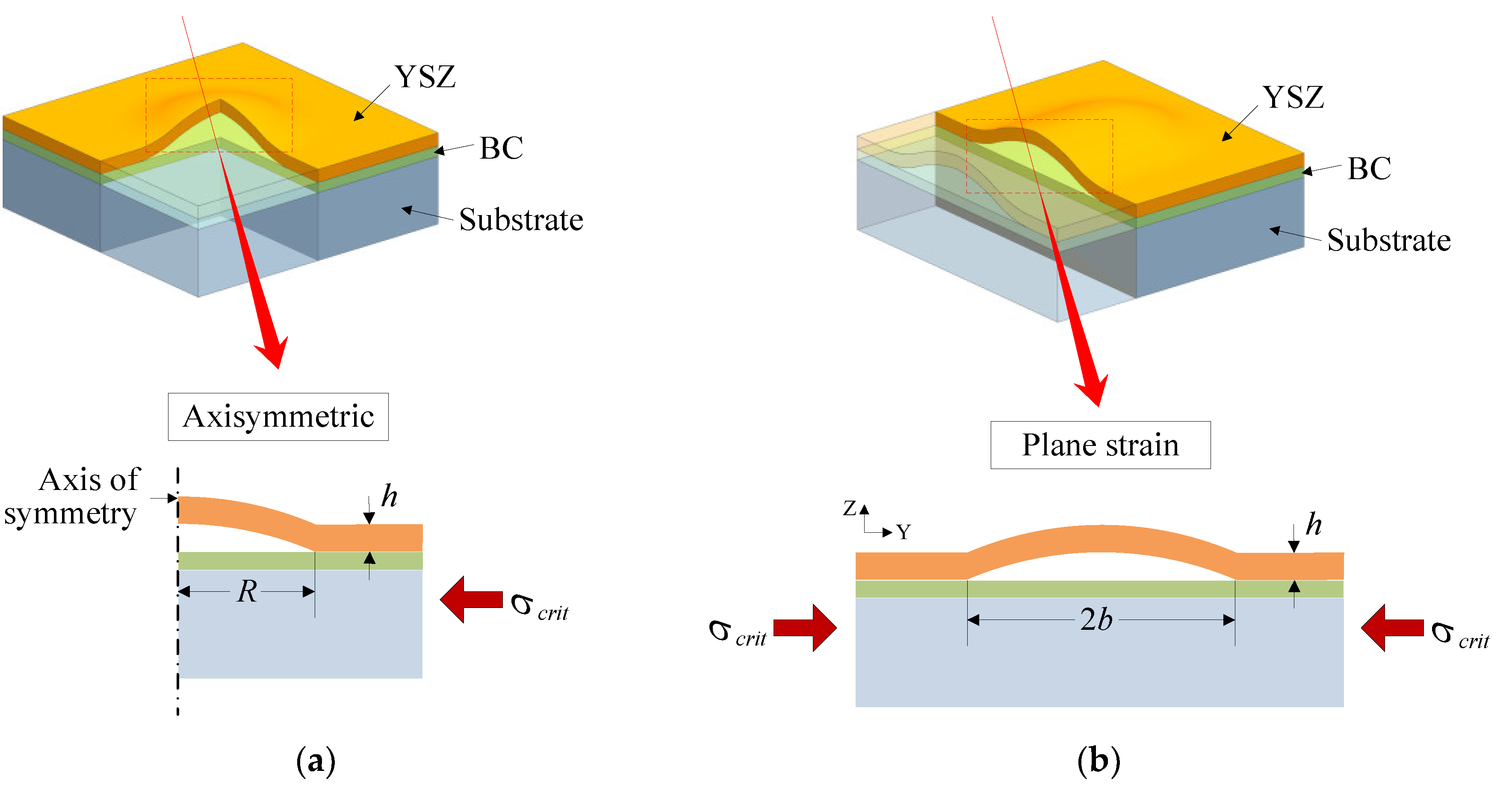
  • The interfacial damage of TBC can be expressed as a function of the critical compressive strain inducing the coating spallation at room temperature and the initial residual strain as well as the thickness of the YSZ and the elastic constants of the coating. The presence of the initial residual strain causes the interfacial damage threshold corresponding to coating spallation to be less than 1. The decrease in the residual spalling resistance is used to define the interfacial damage, and there is no direct correlation between the derived interfacial damage equation and the adopted buckling mode assumption.
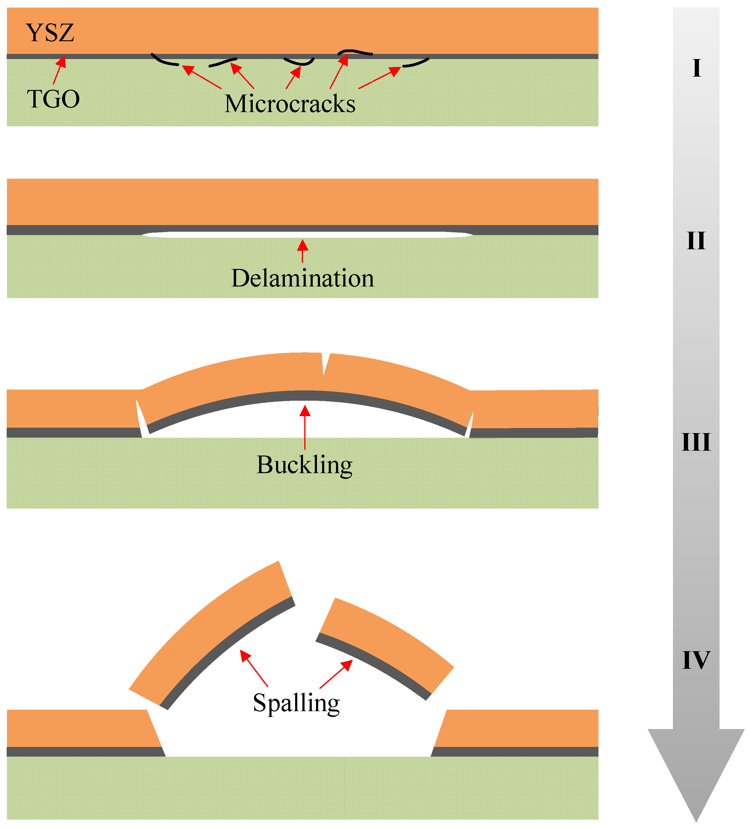
  • The residual spalling resistance of the coating under different thermal loads can be characterized in a unified manner by the critical compressive strain. The abrupt change in the slope of the surface compressive strain of the coating due to the onset of TBC buckling can be used as a criterion in conjunction with DIC noncontact strain field testing technology to achieve accurate extraction of the critical compressive strain. The critical compressive strain gradually decreases with increasing isothermal oxidation time and the number of thermal cycles, indicating that the interfacial bond strength decreases progressively due to TGO growth as well as stress and strain cycles in the coating, i.e., interfacial damage accumulation.
  • The interfacial damage of TBC produced by the isothermal oxidation experiments exhibits a power-law relationship with the oxidation time, and the damage rate increases gradually with the oxidation time, while the interfacial damage produced by the thermal fatigue experiments is approximately linearly related to the number of thermal cycles, and the damage rate remains constant. The interfacial damage is linked to the TGO thickness through a power law under the two test conditions. In addition, with the same TGO thickness, the interfacial damage caused by the thermal fatigue experiments is greater than that caused by isothermal oxidation, indicating that the stress–strain cycles in the coating caused additional mechanically driven damage.
  • The total damage generated at the coating interface can be divided into three parts: the oxidatively driven damage related to the growth of TGO, the mechanically driven damage linked to the stress–strain cycles in the coating, and their interaction. The available results show that the interaction term between oxidatively driven damage and mechanically driven damage should be taken as a negative value, i.e., the total interfacial damage in the thermal fatigue experiments is smaller than the sum of the oxidatively driven damage and mechanically driven damage. The evolution of the interface morphology caused by TGO growth and rumpling under thermal fatigue loading may be one of the reasons for the above phenomenon.

Author Contributions

Conceptualization, methodology, data curation, writing—original draft preparation, writing—review and editing, F.J. and J.Y.; project administration, funding acquisition, Q.W. and F.J.; data curation, S.T.; funding acquisition, T.Z., J.W. and X.F. All authors have read and agreed to the published version of the manuscript.

Funding

This research was funded by the National Natural Science Foundation of China, grant number 51905510, and the National Science and Technology Major Project, grant number J2019-IV-0003-0070 and J2019-V-0006-0099.

Institutional Review Board Statement

Not applicable.

Informed Consent Statement

Not applicable.

Data Availability Statement

Not applicable.

Conflicts of Interest

The authors declare no conflict of interest.

References

  1. Peters, M.; Leyens, C.; Schulz, U.; Kaysser, W. EB-PVD Thermal Barrier Coatings for Aeroengines and Gas Turbines. Adv. Eng. Mater. 2001, 3, 193–205. [Google Scholar] [CrossRef]
  2. Nissley, D.M. Thermal barrier coating life modeling in aircraft gas turbine engines. J. Therm. Spray Technol. 1997, 6, 91–98. [Google Scholar] [CrossRef] [Green Version]
  3. Schulz, U.; Leyens, C.; Fritscher, K.; Peters, M.; Saruhan-Brings, B.; Lavigne, O.; Dorvaux, J.-M.; Poulain, M.; Mévrel, R.; Caliez, M. Some recent trends in research and technology of advanced thermal barrier coatings. Aerosp. Sci. Technol. 2003, 7, 73–80. [Google Scholar] [CrossRef]
  4. Manero, A.; Sofronsky, S.; Knipe, K.; Meid, C.; Wischek, J.; Okasinski, J.; Almer, J.; Karlsson, A.M.; Raghavan, S.; Bartsch, M. Monitoring local strain in a thermal barrier coating system under thermal mechanical gas turbine operating conditions. JOM 2015, 67, 1528–1539. [Google Scholar] [CrossRef]
  5. Yunus, S.M.; Mahalingam, S.; Manap, A.; Afandi, N.M.; Satgunam, M. Test-rig simulation on hybrid thermal barrier coating assisted with cooling air system for advanced gas turbine under prolonged exposures—A review. Coatings 2021, 11, 560. [Google Scholar] [CrossRef]
  6. Gao, R.; Mao, W.; Wang, Y.; Fan, S.; Shao, W. Intelligent life lrediction of thermal barrier coating for aero engine blades. Coatings 2021, 11, 890. [Google Scholar] [CrossRef]
  7. Maurel, V.; Bartsch, M.; Vidal-Sétif, M.-H.; Vaßen, R.; Guipont, V. Coated single crystal superalloys: Processing, characterization, and modeling of protective coatings. In Nickel Base Single Crystals Across Length Scales, 1st ed.; Cailletaud, G., Cormier, J., Eggeler, G., Maurel, V., Nazé, L., Eds.; Elsevier: Amsterdam, The Netherlands, 2022; Volume 10, pp. 283–338. [Google Scholar] [CrossRef]
  8. Evans, A.G.; Mumm, D.R.; Hutchinson, J.W.; Meier, G.H.; Pettit, F.S. Mechanisms controlling the durability of thermal barrier coatings. Prog. Mater. Sci. 2001, 46, 505–553. [Google Scholar] [CrossRef]
  9. Daroonparvar, M.; Yajid, M.A.M.; Kay, C.M.; Bakhsheshi-Rad, H.; Gupta, R.K.; Yusof, N.M.; Ghandvar, H.; Arshad, A.; Zulkifli, I.S.M. Effects of Al2O3 diffusion barrier layer (including Y-containing small oxide precipitates) and nanostructured YSZ top coat on the oxidation behavior of HVOF NiCoCrAlTaY/APS YSZ coatings at 1100 °C. Corros. Sci. 2018, 144, 13–34. [Google Scholar] [CrossRef]
  10. Daroonparvar, M.; Yajid, M.A.M.; Yusof, N.M.; Hussain, M.S. Improved Thermally Grown Oxide Scale in Air Plasma Sprayed NiCrAlY/Nano-YSZ Coatings. J. Nanomater. 2013, 2013, 520104. [Google Scholar] [CrossRef] [Green Version]
  11. Ozgurluk, Y.; Doleker, K.M.; Ozkan, D.; Ahlatci, H.; Karaoglanli, A.C. Cyclic Hot Corrosion Failure Behaviors of EB-PVD TBC Systems in the Presence of Sulfate and Vanadate Molten Salts. Coatings 2019, 9, 166. [Google Scholar] [CrossRef] [Green Version]
  12. Vorkötter, C.; Mack, D.E.; Zhou, D.; Guillon, O.; Vaßen, R. Effect of Low-CTE Oxide-Dispersion-Strengthened Bond Coats on Columnar-Structured YSZ Coatings. Coatings 2022, 12, 396. [Google Scholar] [CrossRef]
  13. Wee, S.; Do, J.; Kim, K.; Lee, C.; Seok, C.; Choi, B.-G.; Choi, Y.; Kim, W. Review on mechanical thermal properties of superalloys and thermal barrier coating used in gas turbines. Appl. Sci. 2020, 10, 5476. [Google Scholar] [CrossRef]
  14. Wen, Q.; Jing, F.; Zhang, C.; Tang, S.; Yang, J. Review of numerical simulation of TGO growth in thermal barrier coatings. Comput. Model. Eng. Sci. 2022, 132, 361–391. [Google Scholar] [CrossRef]
  15. Padture, N.P.; Gell, M.; Jordan, E.H. Thermal barrier coatings for gas-turbine engine applications. Science 2002, 296, 280–284. [Google Scholar] [CrossRef] [PubMed]
  16. Patel, N.V.; Jordan, E.H.; Sridharan, S.; Gell, M. Cyclic furnace testing and life predictions of thermal barrier coating spallation subject to a step change in temperature or in cycle duration. Surf. Coat. Technol. 2015, 275, 384–391. [Google Scholar] [CrossRef] [Green Version]
  17. Nychka, J.; Clarke, D. Damage quantification in TBCs by photo-stimulated luminescence spectroscopy. Surf. Coat. Technol. 2001, 146–147, 110–116. [Google Scholar] [CrossRef]
  18. Selçuk, A.; Atkinson, A. The evolution of residual stress in the thermally grown oxide on Pt diffusion bond coats in TBCs. Acta Mater. 2003, 51, 535–549. [Google Scholar] [CrossRef]
  19. Tolpygo, V.; Clarke, D.; Murphy, K. Evaluation of interface degradation during cyclic oxidation of EB-PVD thermal barrier coatings and correlation with TGO luminescence. Surf. Coat. Technol. 2004, 188–189, 62–70. [Google Scholar] [CrossRef]
  20. Sridharan, S.; Xie, L.; Jordan, E.H.; Gell, M. Stress variation with thermal cycling in the thermal grown oxide of an EB-PVD thermal barrier coating. Surf. Coat. Technol. 2004, 179, 286–296. [Google Scholar] [CrossRef]
  21. Wen, M.; Jordan, E.H.; Gell, M. Evolution of photo-stimulated luminescence of EB-PVD/(Ni, Pt)Al thermal barrier coatings. Mater. Sci. Eng. A 2005, 398, 99–107. [Google Scholar] [CrossRef]
  22. Lee, G.; Atkinson, A.; Selçuk, A. Development of residual stress and damage in thermal barrier coatings. Surf. Coat. Technol. 2006, 201, 3931–3936. [Google Scholar] [CrossRef]
  23. Busso, E.; Wright, L.; Evans, H.; McCartney, L.; Saunders, S.; Osgerby, S.; Nunn, J. A physics-based life prediction methodology for thermal barrier coating systems. Acta Mater. 2007, 55, 1491–1503. [Google Scholar] [CrossRef] [Green Version]
  24. Rinaldi, C.; De Maria, L.; Mandelli, M. Assessment of the spent life fraction of gas turbine blades by coating life modeling and photostimulated luminescence piezospectroscopy. J. Eng. Gas Turbines Power 2010, 132, 114501. [Google Scholar] [CrossRef]
  25. Manero, A.; Selimov, A.; Fouliard, Q.; Knipe, K.; Wischek, J.; Meid, C.; Karlsson, A.M.; Bartsch, M.; Raghavan, S. Piezospectroscopic evaluation and damage identification for thermal barrier coatings subjected to simulated engine environments. Surf. Coat. Technol. 2017, 323, 30–38. [Google Scholar] [CrossRef]
  26. Renusch, D.; Schütze, M. Measuring and modeling the TBC damage kinetics by using acoustic emission analysis. Surf. Coat. Technol. 2007, 202, 740–744. [Google Scholar] [CrossRef]
  27. Yang, L.; Zhou, Y.; Lu, C. Damage evolution and rupture time prediction in thermal barrier coatings subjected to cyclic heating and cooling: An acoustic emission method. Acta Mater. 2011, 59, 6519–6529. [Google Scholar] [CrossRef] [Green Version]
  28. Ma, X.; Cho, S.; Takemoto, M. Acoustic emission source analysis of plasma sprayed thermal barrier coatings during four-point bend tests. Surf. Coat. Technol. 2001, 139, 55–62. [Google Scholar] [CrossRef]
  29. Aleksanoglu, H.; Scholz, A.; Oechsner, M.; Berger, C.; Rudolphi, M.; Schütze, M.; Stamm, W. Determining a critical strain for APS thermal barrier coatings under service relevant loading conditions. Int. J. Fatigue 2011, 53, 40–48. [Google Scholar] [CrossRef]
  30. Yang, L.; Zhong, Z.; You, J.; Zhang, Q.; Zhou, Y.; Tang, W. Acoustic emission evaluation of fracture characteristics in thermal barrier coatings under bending. Surf. Coat. Technol. 2013, 232, 710–718. [Google Scholar] [CrossRef]
  31. Zhu, W.; Yang, L.; Guo, J.; Zhou, Y.; Lu, C. Determination of interfacial adhesion energies of thermal barrier coatings by compression test combined with a cohesive zone finite element model. Int. J. Plast. 2014, 64, 76–87. [Google Scholar] [CrossRef]
  32. Kim, D.-J.; Shin, I.-H.; Koo, J.-M.; Seok, C.-S.; Lee, T.-W. Failure mechanisms of coin-type plasma-sprayed thermal barrier coatings with thermal fatigue. Surf. Coat. Technol. 2010, 205, S451–S458. [Google Scholar] [CrossRef]
  33. Song, H.; Kim, Y.; Lee, J.-M.; Yun, J.; Kim, D.-J.; Koo, J.-M.; Seok, C.-S. Life prediction of thermal barrier coating considering degradation and thermal fatigue. Int. J. Precis. Eng. Manuf. 2016, 17, 241–245. [Google Scholar] [CrossRef]
  34. Courcier, C.; Maurel, V.; Rémy, L.; Quilici, S.; Rouzou, I.; Phelippeau, A. Interfacial damage based life model for EB-PVD thermal barrier coating. Surf. Coat. Technol. 2011, 205, 3763–3773. [Google Scholar] [CrossRef]
  35. Rémy, L.; Guerre, C.; Rouzou, I.; Molins, R. Assessment of TBC oxidation-induced degradation using compression tests. Oxid. Met. 2013, 81, 3–15. [Google Scholar] [CrossRef]
  36. Wang, J.-S.; Evans, A. Measurement and analysis of buckling and buckle propagation in compressed oxide layers on superalloy substrates. Acta Mater. 1998, 46, 4993–5005. [Google Scholar] [CrossRef]
  37. Wang, J.; Evans, A. Effects of strain cycling on buckling, cracking and spalling of a thermally grown alumina on a nickel-based bond coat. Acta Mater. 1999, 47, 699–710. [Google Scholar] [CrossRef]
  38. Yanar, N.M.; Pettit, F.S.; Meier, G.H. Failure characteristics during cyclic oxidation of yttria stabilized zirconia thermal barrier coatings deposited via electron beam physical vapor deposition on platinum aluminide and on NiCoCrAlY bond coats with processing modification for improved performances. Met. Mater. Trans. A 2006, 37, 1563–1580. [Google Scholar] [CrossRef]
  39. Wright, P.K. Influence of cyclic strain on life of a PVD TBC. Mater. Sci. Eng. A 1998, 245, 191–200. [Google Scholar] [CrossRef]
  40. Harvey, M.; Courcier, C.; Maurel, V.; Rémy, L. Oxide and TBC spallation in β-NiAl coated systems under mechanical loading. Surf. Coat. Technol. 2008, 203, 432–436. [Google Scholar] [CrossRef]
  41. Maurel, V.; de Bodman, P.; Rémy, L. Influence of substrate strain anisotropy in TBC system failure. Surf. Coat. Technol. 2011, 206, 1634–1639. [Google Scholar] [CrossRef]
  42. Hutchinson, J.; Suo, Z. Mixed mode cracking in layered materials. Adv. Appl. Mech. 1992, 29, 63–191. [Google Scholar] [CrossRef]
  43. Zhao, X.; Liu, J.; Rickerby, D.; Jones, R.; Xiao, P. Evolution of interfacial toughness of a thermal barrier system with a Pt-diffused γ/γ’ bond coat. Acta Mater. 2011, 59, 6401–6411. [Google Scholar] [CrossRef]
  44. Jing, F.; Yang, J.; Yang, Z.; Zeng, W. Critical compressive strain and interfacial damage evolution of EB-PVD thermal barrier coating. Mater. Sci. Eng. A 2020, 776, 139038. [Google Scholar] [CrossRef]
  45. Tolpygo, V.; Clarke, D. Morphological evolution of thermal barrier coatings induced by cyclic oxidation. Surf. Coat. Technol. 2003, 163–164, 81–86. [Google Scholar] [CrossRef]
  46. Wright, P.; Evans, A. Mechanisms governing the performance of thermal barrier coatings. Curr. Opin. Solid State Mater. Sci. 1999, 4, 255–265. [Google Scholar] [CrossRef]
  47. Sohn, Y.; Kim, J.; Jordan, E.; Gell, M. Thermal cycling of EB-PVD/MCrAlY thermal barrier coatings: I. microstructure development and spallation mechanisms. Surf. Coat. Technol. 2001, 146–147, 70–78. [Google Scholar] [CrossRef]
  48. Munawar, A.U.; Schulz, U.; Cerri, G.; Lau, H. Microstructure and cyclic lifetime of Gd and Dy-containing EB-PVD TBCs deposited as single and double-layer on various bond coats. Surf. Coat. Technol. 2014, 245, 92–101. [Google Scholar] [CrossRef]
  49. Tolpygo, V.; Clarke, D.; Murphy, K. Oxidation-induced failure of EB-PVD thermal barrier coatings. Surf. Coat. Technol. 2001, 146–147, 124–131. [Google Scholar] [CrossRef]
  50. Liang, J.; Matsumoto, K.; Kawagishi, K.; Harada, H. Morphological evolution of thermal barrier coatings with equilibrium (EQ) and NiCoCrAlY bond coats during thermal cycling. Surf. Coat. Technol. 2012, 207, 413–420. [Google Scholar] [CrossRef]
  51. Li, M.; Sun, X.; Hu, W.; Guan, H. Thermal shock behavior of EB-PVD thermal barrier coatings. Surf. Coat. Technol. 2007, 201, 7387–7391. [Google Scholar] [CrossRef]
  52. Meier, S.M.; Nissley, D.M.; Sheffler, K.D.; Cruse, T.A. Thermal barrier coating life prediction model development. J. Eng. Gas Turbines Power 1992, 114, 258–263. [Google Scholar] [CrossRef]
  53. Ogiriki, E.A.; Li, Y.G.; Nikolaidis, T. Prediction and analysis of impact of TBC oxidation on gas turbine creep life. In Proceedings of the ASME Turbo Expo 2015, GT2015-42177, Montreal, QU, Canada, 15–19 June 2015. [Google Scholar] [CrossRef]
  54. Zhang, Y.; Deng, H.; Shi, H.; Yu, H.; Zhong, B. Failure characteristics and life prediction for thermally cycled thermal barrier coatings. Surf. Coat. Technol. 2012, 206, 2977–2985. [Google Scholar] [CrossRef]
  55. Knipe, K.; Manero, A.; Siddiqui, S.F.; Meid, C.; Wischek, J.; Okasinski, J.; Almer, J.; Karlsson, A.M.; Bartsch, M.; Raghavan, S. Strain response of thermal barrier coatings captured under extreme engine environments through synchrotron X-ray diffraction. Nat. Commun. 2014, 5, 4559. [Google Scholar] [CrossRef] [PubMed] [Green Version]
  56. Pan, B. Digital image correlation for surface deformation measurement: Historical developments, recent advances and future goals. Meas. Sci. Technol. 2018, 29, 082001. [Google Scholar] [CrossRef]
  57. Wen, M.; Jordan, E.H.; Gell, M. Effect of temperature on rumpling and thermally grown oxide stress in an EB-PVD thermal barrier coating. Surf. Coat. Technol. 2006, 201, 3289–3298. [Google Scholar] [CrossRef]
  58. Maurel, V.; Busso, E.; Frachon, J.; Besson, J.; N’Guyen, F. A methodology to model the complex morphology of rough interfaces. Int. J. Solids Struct. 2014, 51, 3293–3302. [Google Scholar] [CrossRef]
  59. Chen, Y.; Zhao, X.; Bai, M.; Yang, L.; Li, C.; Wang, L.; Carr, J.; Xiao, P. A mechanistic understanding on rumpling of a NiCoCrAlY bond coat for thermal barrier coating applications. Acta Mater. 2017, 128, 31–42. [Google Scholar] [CrossRef]
Figure 1. Typical thermal barrier coating system and its application in aeroengines.
Coatings 12 00984 g001
Figure 2. Four stages during the spalling of EB-PVD thermal barrier coating: (I) microcracks initiate and propagate at the interface; (II) interfacial delamination due to adjacent microcracks coalesces; (III) the debonded YSZ buckles from the BC; (IV) the spalling or brittle fractures of the YSZ due to excessive bending deformation.
Coatings 12 00984 g002
Figure 3. Schematic of the buckling of ceramic layers under compressive loading: (a) the axisymmetric blister; (b) the straight-sided blister.
Coatings 12 00984 g003
Figure 4. Schematic of coating loadings under the axial compression test.
Coatings 12 00984 g004
Figure 5. Hourglass specimens with EB-PVD TBC.
Coatings 12 00984 g005
Figure 6. Schemas of the experiments and quantitative characterization of damage in TBC.
Coatings 12 00984 g006
Figure 7. Schemas of thermal loadings in the test: (a) isothermal oxidation loading and (b) thermal fatigue loading.
Coatings 12 00984 g007
Figure 8. Schemas of DIC method: (I) spray speckles on the specimen to mark locations and calibrate parameters; (II) record the speckles’ motion in real time with calibrated cameras; (III) determine the displacement and strain of the coating surface using the image matching algorithm.
Coatings 12 00984 g008
Figure 9. The variation of compressive strain distribution on the surface of TBC obtained by DIC.
Coatings 12 00984 g009
Figure 10. Spontaneous spalling of the coating after 783 thermal cycles, caused by the residual strain of the ceramic layer itself with approximate straight-side blister buckling mode.
Coatings 12 00984 g010
Figure 11. The extraction process of TGO thickness using SEM: (a) SEM image of TBC interface, (b) TGO contour is extracted according to the sudden change of gray level on the boundary, and (c) TGO upper and lower boundary coordinates are extracted to calculate TGO thickness.
Coatings 12 00984 g011
Figure 12. Evolutions of the critical compression strain with thermal loads.
Coatings 12 00984 g012
Figure 13. Evolutions of the interfacial damage with thermal loads.
Coatings 12 00984 g013
Figure 14. Evolutions of the TGO thickness with thermal loads.
Coatings 12 00984 g014
Figure 15. Correlation between interface damage and TGO thickness.
Coatings 12 00984 g015
Figure 16. Decoupling of interfacial damages due to thermal fatigue.
Coatings 12 00984 g016
Figure 17. Evolution of the interface morphology with thermal cycles.
Coatings 12 00984 g017
Table 1. The composition of substrate with PWA1484.
CoCrMoWTaReTiAlCNi
1051.768.5315.50.02Bal
Table 2. The composition of bond coating with NiCrAlYSi.
CrAlYSiCuFeNi
15–2010–150.2–1.00.6–1.2≤0.05≤0.5Bal
Table 3. Parameters in the equation of interfacial damage.
h ν 1 ν s T p r o T r e f α 1 α s
100 μm0.10.421000 °C20 °C10.33 × 10−615 × 10−6
Publisher’s Note: MDPI stays neutral with regard to jurisdictional claims in published maps and institutional affiliations.

