Article

Microstructure and Wear Resistance of TiCp/Ti6Al4V Composite Coatings by Follow-Up Ultrasonic-Assisted Laser Additive Manufacturing

1
Key Laboratory for Precision and Non-Traditional Machining Technology of Ministry of Education, Dalian University of Technology, Dalian 116024, China
2
Shanghai Marine Diesel Engine Research Institute, Shanghai 201108, China
*
Author to whom correspondence should be addressed.
Coatings 2022, 12(7), 986; https://doi.org/10.3390/coatings12070986
Submission received: 25 May 2022 / Revised: 5 July 2022 / Accepted: 10 July 2022 / Published: 12 July 2022

Abstract

:
With the increasing demand for the high agility and fast response of high-level equipment in the aerospace and energy power fields, it is increasingly urgent to improve the performance of the high-temperature and wear resistance of the corresponding high-level components. Ceramic-reinforced titanium matrix composites have excellent high-temperature and wear resistance, but, in laser additive manufacturing, the primary ceramic phase is coarse, and the morphology of the ceramic phase is difficult to control, which limits their further development. In this investigation, a follow-up ultrasonic-assisted laser-additive-manufacturing method was proposed to prepare a 30 wt.% TiC/Ti6Al4V composite coating on a Ti6Al4V surface. Under the effects of ultrasonic cavitation and acoustic streaming, the content of the unmelted TiC was reduced, the dendritic primary TiC in the solidification process was broken and the distribution uniformity of the primary TiC was improved. The content of the unmelted TiC in the composite coating decreased significantly under ultrasonic action, and it was only 50.23% of that without ultrasonic action. At the same time, the average size of the dendritic primary TiC in the composite coating decreased from 61.59 μm to 27.04 μm, which was 56.10% smaller than that without ultrasonic action. The average microhardness of the composite coating reached the maximum of 656.70 HV0.2 under ultrasonic power, and it was 83.21% higher than that of the Ti6Al4V substrate, and 26.44% higher than that of the composite coating without ultrasonic power. Due to the ultrasonic-cavitation and acoustic-streaming effects, the content of the unmelted TiC obviously decreased, so that the average friction coefficient of the composite coating increased, and the wear mechanism changed from abrasive wear to adhesive wear.

1. Introduction

Ti6Al4V has high specific strength, excellent heat and corrosion resistance and it is widely used in high-end components, such as in aircraft engine casings and turbine blades. Due to the poor wear resistance of TC4, the application in many harsh environments is limited, and with the development of high-level equipment, higher requirements are being put forward for the heat and wear resistance of Ti6Al4V components [1,2,3,4]. With the continuous development of laser-additive-manufacturing technology, cladding-ceramic-reinforced metal-matrix composite coatings on Ti6Al4V surfaces are considered to be an effective means to improve the hardness and wear resistance of Ti6Al4V components. Currently, WC, TiB, TiN, Si3N4, TiC and other ceramic materials can be used as reinforcement for titanium alloy. The density and thermal-expansion coefficients of TiC and Ti6Al4V are close, and so TiC is considered to be one of the excellent reinforcing materials for the preparation of titanium-based composite coatings [5]. Because the laser-additive-manufacturing process has the characteristics of rapid melting and rapid solidification, it is prone to the uneven distribution of the microstructure, which greatly limits the application of ceramic-reinforced metal-matrix composite coatings in engineering.
Ultrasound has the advantages of high energy density and good directionality [6]. The cavitation effect, acoustic-flow effect, mechanical effect and thermal effect that are generated when ultrasonic waves propagate in the liquid medium can interfere with the fusion behavior of the laser-additive molten pool to some extent [7], so as to reduce the coarse tendency of the microstructure. Some scholars have carried out research on ultrasonic-assisted laser-additive-manufacturing technology.
The effect of ultrasonic-assisted laser additive manufacturing is affected by the method of ultrasonic application. At present, there are mainly two ways of ultrasonic application: nondirect connection and direct connection. Wang et al. [8] used ultrasonic-assisted laser-additive-manufacturing technology to prepare a 3540Fe/CeO2 composite coating on the surface of 42CrMo steel. The ultrasonic application method was nondirect connection, and the influence of the ultrasonic incident angle on the macromorphology and microhardness of the composite coating was studied. The nondirected-ultrasound-application method suffers from serious ultrasound energy loss, and the distance of action is difficult to grasp, and so scholars are more likely to choose the direct-connected ultrasound application method. Weilong Cong et al. prepared Fe–Cr stainless steel parts by bottom ultrasound-assisted direct laser deposition. The addition of ultrasound reduced the number of pores and cracks and improved the microhardness of the samples [9]. Li Meiyan et al. introduced ultrasound into the direct-laser-deposition process and prepared Ni/WC/La2O3 coatings on the surface of 45 steel. The effects of different ultrasound powers on the microstructure and mechanical properties of the coatings were investigated, and the WC particles were mostly uniformly distributed when the ultrasound power was 800 W. At this time, the hardness and wear resistance of the coatings were most significantly enhanced [10]. Current research results have confirmed that ultrasonic-assisted laser additive manufacturing has a good effect on improving the microstructures of composite coatings, but these methods are limited by the form of the energy field applied, which makes it difficult to achieve precise and efficient intervention in the additive manufacturing process. In this paper, a follow-up ultrasonic-assisted laser-additive-manufacturing method is proposed to intervene in the solidification behavior of the melt pool in real time by using the effects of ultrasonic cavitation and acoustic streaming [11,12,13,14], and the effect of the ultrasonic power on the microstructure and mechanical properties of the TiC-reinforced Ti6Al4V composite coatings was studied.

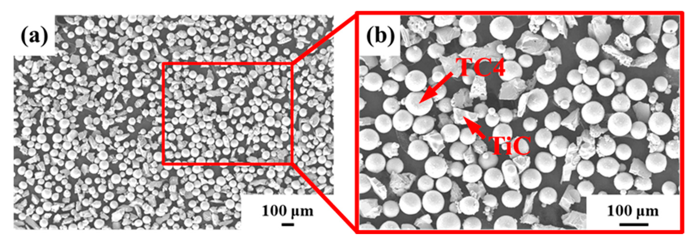
2. Experimental Materials and Process

The substrate material in the experiment was Ti6Al4V, with dimensions of 130 mm × 130 mm × 9 mm. The surface of the substrate was polished with sandpaper to remove oil and oxidation layers on the surface. The composite coating material was a 30 wt.% TiC/Ti6Al4V composite powder, with an average particle size distribution of 45–90 μm. The morphology of the composite powder is shown in Figure 1. Before the experiment, the mixed powder was placed in a vacuum-drying oven and was dried at 120 °C for 6 h to remove moisture.
The schematic diagram of the follow-up ultrasonic-assisted laser-additive-manufacturing system is shown in Figure 2. We used ultrasonic vibration equipment (including an ultrasonic generator and ultrasonic head) (Hangzhou Fansonic Ultrasonic Technology Co., Ltd., Hangzhou, China), and an Nd:YAG continuous laser device (JK1002, GSI Lumonics, Bedford, MA, USA). The laser beam and the powder converge at the front of the nozzle to form a melt pool 10 mm away from the laser head, and the ultrasonic impact head is arranged at the rear of the nozzle. Ultrasound is delivered to the melt pool through the ultrasonic impact head and the already-solidified composite coating, which intervenes in the solidification behavior of the melt pool to realize the follow-up ultrasonic-assisted laser additive manufacturing of titanium-based coatings.
In this investigation, four groups of ultrasonic power (0, 1400, 1600, and 1800 W) were set up to investigate the effects of different ultrasonic powers on the microstructure and wear resistance of composite coatings. The other process parameters were as follows: a laser power of 550 W, scanning speed of 150 mm/min, powder feeding rate of 1.6 g/min, ultrasonic frequency of 20 kHz, ultrasonic incidence angle of 30°, ultrasonic tool-head preload of 117 N, and a horizontal distance between the ultrasonic action point and the deposition position of 10 mm.
To grind and polish the section of the sample, we first used 320#, 600#, 1000#, #1500, 2000# sandpaper, and finally used 1.5 μm diamond-polishing paste to polish the section. The phase composition in the composite coating was analyzed using an X-ray (XRD-6000, Shimadzu, Kyoto, Japan) diffractometer at a scanning angle from 30° to 90°, with a step size of 0.02°. The distributions of the Ti, Al, V and C elements in the composite coating were analyzed by a JXA-8530 electron probe analyzer. Field-emission scanning electron microscopy (SEM) was used to observe the cross-sectional morphology, content and distribution of the unfused TiC and primary TiC in the composite coating. An energy spectrometer was used to determine the phase composition and distribution of elements. The grain size and texture characteristics of the α-Ti were analyzed by the electron-backscatter-diffraction (EBSD) module in the SEM system. A JEM-2100 F field-emission transmission electron microscope was used to analyze the interface bonding between the primary TiC and α-Ti.
The microhardness of the composite coating was measured using an HV-1000 A microhardness tester, with a load of 200 g, and a holding time of 20 s. The MMW-1A universal friction and wear tester was used to carry out the pin-disk friction and wear tests at room temperature, with a load of 60 N (3 wear pins), a friction time of 15 min and a turntable speed of 100 rpm. The friction disk was made of hardened 45 steel (hardness: 50 HRC), and the wear pins were 30 wt.% TiCp/Ti6Al4V composite coating.

3. Analysis and Discussion

3.1. Phase Analysis

The XRD spectra of the 30 wt.% TiC/Ti6Al4V composite coatings prepared at different ultrasonic powers are shown in Figure 3. From the figure, it can be seen that the change in the ultrasonic power did not cause any change in the composition of the phases within the composite coating. The composite coating is mainly composed of three phases: TiC, α-Ti and β-Ti, which is consistent with the results of the Ti–C binary phase diagram [15]. With the increase in the ultrasonic power, the (111) and (220) diffraction-peak intensities of the TiC in the composite coating obviously increased. This is mainly because, with the increase in ultrasonic power, the temperature of the molten pool increases, and more TiC particles are melted/dissolved, so that more C elements are distributed in the composite coating, which thus generates more primary TiC. The increased content and uniform distribution of the primary TiC increase the intensity of the TiC diffraction peaks [16].

3.2. Microstructure Analysis

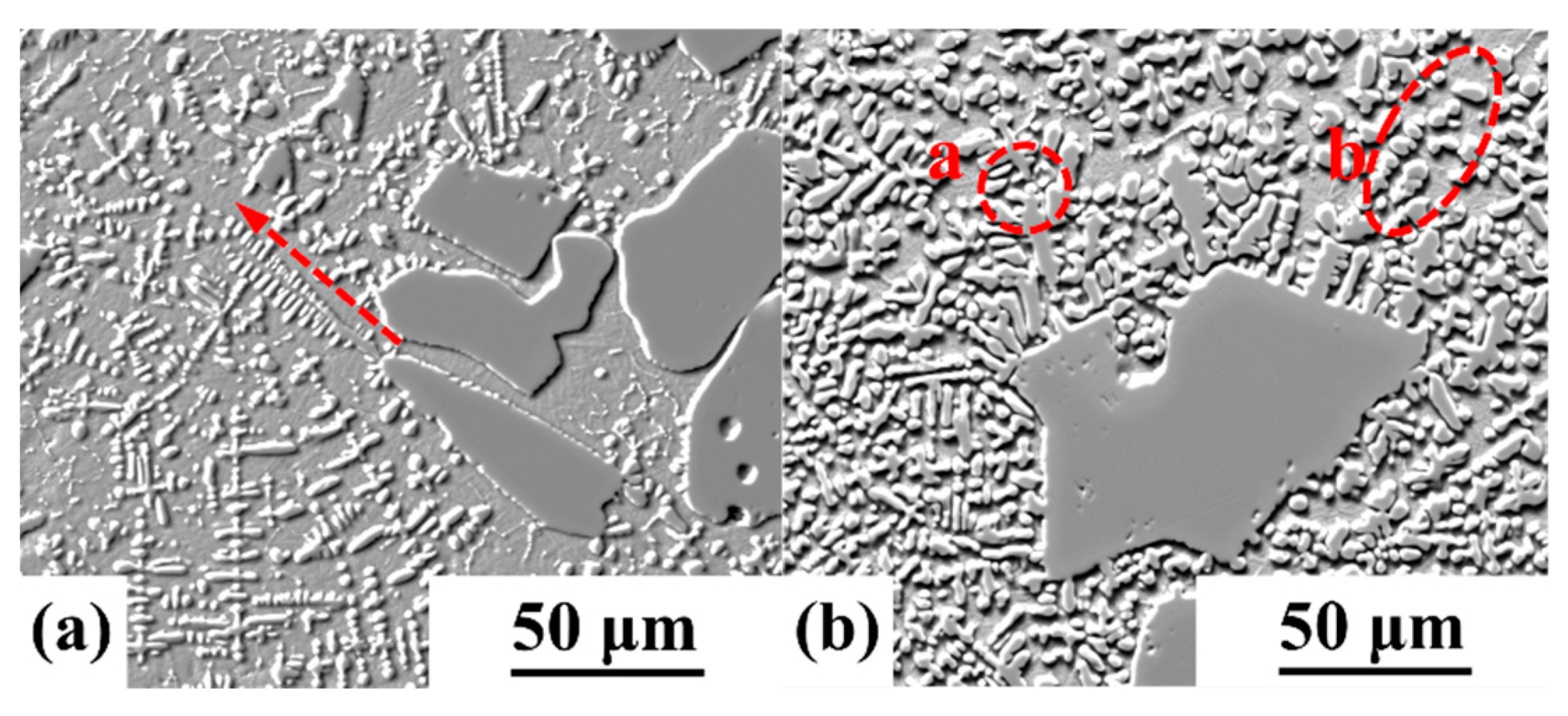
3.2.1. Content and Distribution of Unmelted TiC

The cross-sectional morphology of the 30 wt.% TiC/Ti6Al4V composite coating prepared using the follow-up ultrasonic-assisted laser-additive-manufacturing technology under different ultrasonic powers are shown in Figure 4. As can be seen from the figure, the content and distribution of the unmelted TiC changed significantly.
Under the process parameters used in this paper, the TiC particles did not melt completely, and the same phenomenon was also observed in the work of Yu et al. [17]. When the ultrasonic power was 0 W, the unmelted TiC was randomly distributed within the composite coating. With the increase in the ultrasonic power, the amount of unmelted TiC distributed in the bottom and middle of the composite coating gradually decreased. The content of the unmelted TiC was quantified using the area method, where the unmelted TiC content was the ratio of the area of unmelted TiC to the area of the composite coating. The variation in the unmelted TiC content with ultrasonic power is shown in Figure 5. The unmelted TiC content was 15.31% when there was no ultrasound. With the increase in ultrasonic power, more unmelted TiC was melted/dissolved, and the content of the unmelted TiC decreased significantly. When the ultrasonic power was 1800 W, the content of the unmelted TiC reached a minimum of 7.69%, which was only 50.23% of that without the ultrasonic effect.
The reduction in the unmelted TiC content in the composite coating is related to the intervention of the ultrasound on the solidification process of the melt. The cavitation bubbles produced by the cavitation effect of the ultrasound instantaneously generate high temperatures and pressures when they are broken, which thereby increase the temperature of the molten pool. At the same time, the acoustic-streaming effect of ultrasound will accelerate the flow of the melt pool [18,19], making the unmelted TiC particles and matrix material of the composite coating rub against each other, which generates more heat energy and further increases the melt-pool temperature. The increased temperature of the melt pool will allow more TiC particles to melt/dissolve. It can be seen that the content and distribution of the unmelted TiC within the composite coating can be regulated by changing the ultrasonic power during the follow-up ultrasonic-assisted laser-additive-manufacturing process. The unmelted TiC particles are prepared by the mechanical crushing method and have irregular shapes. There are stress concentration points at the sharp corners and protrusions. The decrease in the unmelted TiC particles is beneficial to improve the uniformity of the stress distribution in the composite coating.

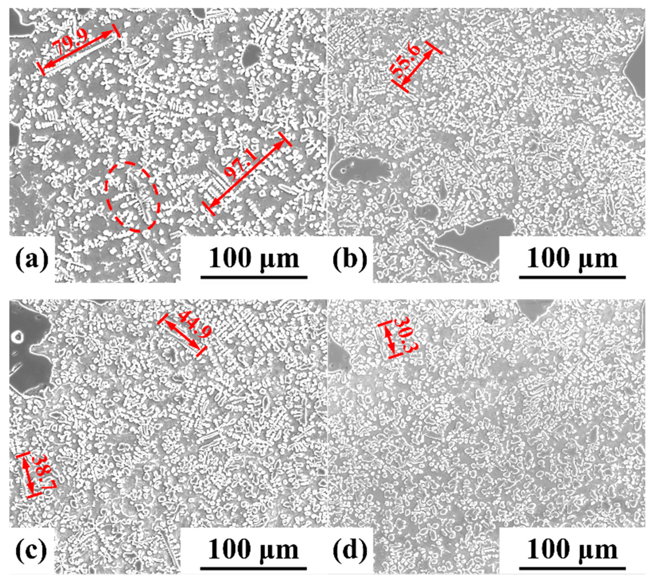
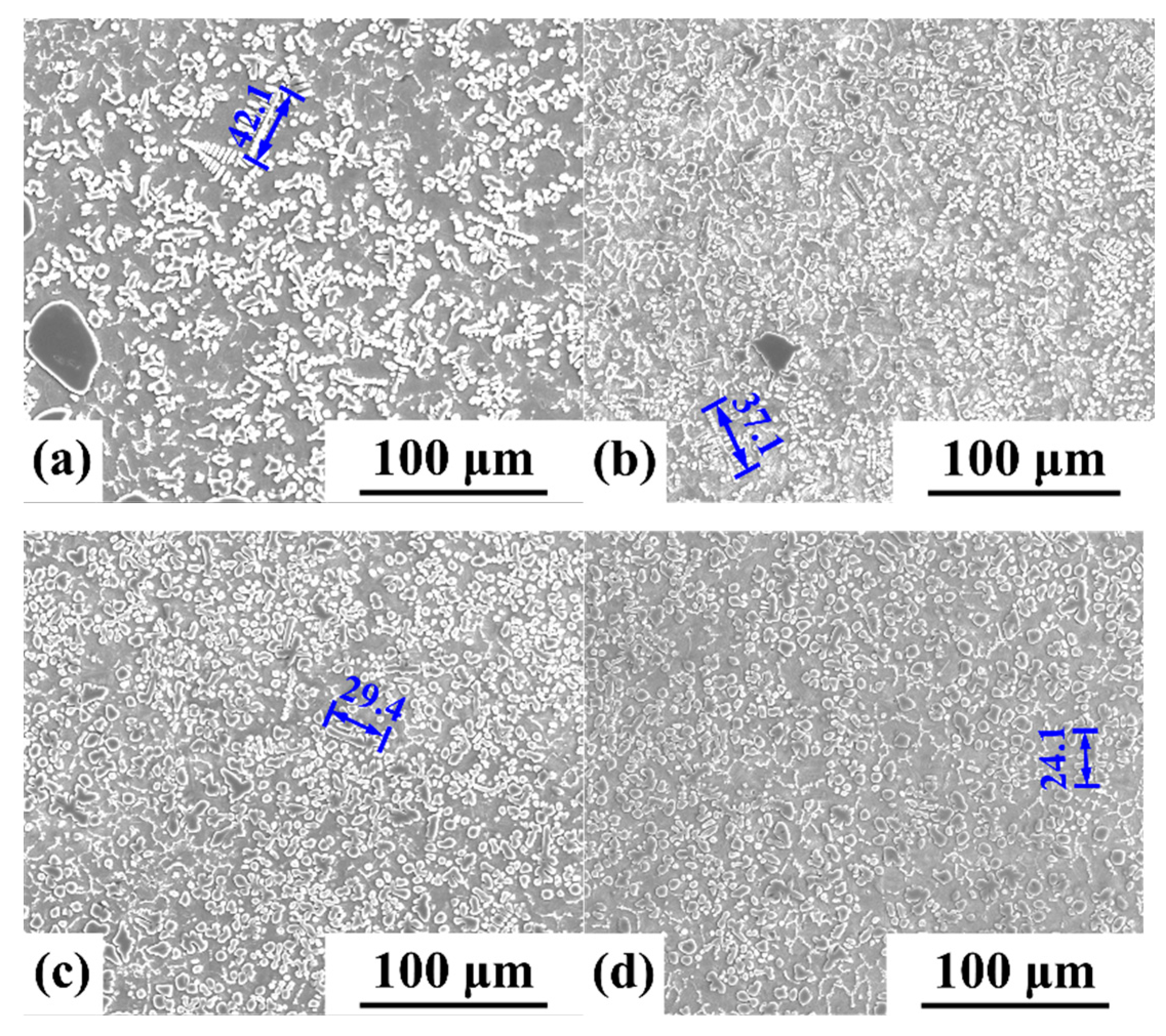
3.2.2. Content and Distribution of Primary TiC

There is a large amount of dendritic primary TiC in the composite coating. It is generally believed that the tips of the dendritic primary TiC and the connection between the dendritic trunk and secondary dendritic arms are prone to stress concentration, which can affect the stress distribution in the composite coating. The size and morphology of dendritic primary TiC is mainly influenced by the temperature gradient within the composite coating. In the region with a large temperature gradient in the composite coating, which is the bottom region of the composite coating, the primary TiC grows preferentially in the direction of the greater undercooling and quickly forms a more developed dendritic trunk. On the contrary, the region of smaller temperature gradients is the area on top of the composite coating. The dendritic trunk of the incipient TiC is weakened. Under the scanning electron microscope, the regions at the tops and bottoms of the composite coatings obtained under different ultrasonic powers were observed, and it was found that the morphology and size of the primary TiC changed significantly. The morphology and size of the dendritic primary TiC in the bottom region of the composite coating under different ultrasonic powers are shown in Figure 6. When the ultrasonic power was 0 W, most of the dendritic primary TiC had relatively well-developed secondary dendritic arms, and some of the preferentially grown dendritic primary TiC even had tertiary dendritic arms [20]. When the ultrasonic power was 1400 W, the number of secondary dendrite arms decreased, and when the ultrasonic power was increased to 1600 W and 1800 W, the characteristics of the dendrite trunk were significantly weakened, and the generation of secondary dendrite arms was basically not observed.
The morphology and size of the dendritic primary TiC in the top region of the composite coating under different ultrasonic powers are shown in Figure 7. When there was no ultrasonic power, dendritic primary TiC and a small amount of chain eutectic TiC were found in the region. With the increase in ultrasonic power, the size of the dendritic primary TiC obviously decreased. When the ultrasonic power reached 1800 W, the dendritic primary TiC basically disappeared, and the primary TiC was mainly granular.
The average sizes of the dendritic primary TiC in different regions of the composite coating were counted, and the results are shown in Figure 8. As the ultrasonic power increased from 0 to 1800 W, the average size of the dendritic primary TiC in the bottom region of the composite coating decreased from 61.59 to 27.04 μm, with a decrease of 56.10%. The average size of the dendritic incipient TiC in the top region of the composite coating decreased from 37.31 to 20.37 μm, with a decrease of 45.40%.
The reduction in the average particle size of the dendritic primary TiC is mainly related to the formation mechanism of the dendritic primary TiC and ultrasonic intervention. Under the action of a high-energy laser beam, TiC and Ti6Al4V are melted/dissolved to form a molten pool. With the decrease in the molten-pool temperature, the TiC will first crystallize and precipitate, and because the direct-laser-deposition process is a rapid melting and rapid solidification process, it is easy to form a large undercooling at the front of the solid–liquid interface. The primary TiC grows preferentially along the direction of high undercooling, and soon forms a dendrite trunk [21,22,23], as shown in Figure 9a. After the ultrasonic energy field is applied, the size of the dendritic primary TiC decreases. On the one hand, the cavitation bubble will be generated during the solidification process of the molten pool due to the cavitation effect of the ultrasonic power. When the cavitation bubble breaks, local high temperature and high pressure will be generated. The pressure will break the dendritic trunk in the solidification process [24], as shown in Point a in Figure 9b. On the other hand, the acoustic streaming of the ultrasound will lead to the instability of the solid–liquid interface during the solidification of the molten pool. The dendrite tips are easily broken and diffuse to the liquid metal region with the flow of the molten pool [25]; thus, the size of the dendritic primary TiC decreases, as is shown in Point b in Figure 9b. It can be seen that ultrasonic intervention helps to reduce the average size of dendritic primary TiC. The higher the ultrasonic power, the more obvious the effect.

3.2.3. Texture Orientation and Grain Size

In order to further analyze the effect of ultrasonic power on the alpha laths in the composite coating, the texture characteristics and grain sizes of the alpha laths were analyzed. The IPF images in the middle of the composite coating under different ultrasonic powers are shown in Figure 10. The phases with dendritic characteristics are primary TiC in Figure 10, and a large number of fine alpha-phase laths are distributed between the adjacent primary TiC. These alpha-phase laths show very rich colors, which indicates that there is no obvious preferred orientation of the alpha laths in the matrix. When preparing 15 vol. % TiC/Ti6Al4V composites, J. B, Fruhauf et al. also found that the texture strength of the matrix alpha laths weakened with the increase in the reinforcement content [26].
The average grain sizes of the alpha laths in the matrix were calculated according to the truncated line method (vertical direction), and the results are shown in Table 1. The change in ultrasonic power can cause the change in the average grain size of alpha laths, but there is no obvious change rule. The average grain size of the alpha laths was 0.84 μm without ultrasonic action. When the ultrasonic power was 1400 W and 1800 W, the average grain sizes of the alpha laths were 0.73 and 0.75 μm, respectively, which were lower than those of the alpha laths without ultrasonic action. When the ultrasonic power was 1600 W, the average grain size of the alpha laths was 1.06 μm, which was higher than the average grain size without ultrasonic action.
The change in the average grain size of the alpha laths in the matrix is mainly affected by the nucleation difficulty, nucleation rate and growth conditions in the molten pool. The calculation of the free energy in the molten pool is shown in Formula (1) [20]. In the formula, ΔG is the free energy in the molten pool, and ΔP is the sound pressure in the molten pool. The addition of an ultrasonic energy field increases the sound-pressure intensity (ΔP) in the molten pool, which thereby increases the free energy (ΔG) in the molten pool.
Δ G = G S G L = Δ H S + T Δ S S + Δ V S Δ P
The traditional nucleation theory is shown in Formulas (2) and (3), where σ is the Gibbs–Thomson coefficient, and f (θ) is the nonuniform nucleation factor (0 < f (θ) < 1). According to Formula (2), the critical nucleation radius (rk) decreases with the increase in the free energy (ΔG). It can be seen from Formula (3) that, with the increase in the free energy (ΔG), the critical nucleation work (ΔGc) decreases. The decrease in the critical nucleation radius (rk) and critical nucleation work (ΔGc) will reduce the nucleation difficulty of the alpha laths in the molten pool. Therefore, the addition of an ultrasonic energy field will reduce the nucleation difficulty of the alpha laths in the molten pool.
r k = 2 σ Δ G
Δ G c = 16 π σ 3 3 Δ G 2 f ( θ )
The discussion of TiC shows that, with the increase in ultrasonic power, more TiC melts/dissolves, which results in more primary TiC. The primary TiC that precipitates first provides heterogeneous nucleation points for the generation of alpha laths, which increases the nucleation rate of the alpha laths. At the same time, the average size of the primary TiC decreases, and the distribution in the composite coating is more uniform, which also limits the free growth of α-Ti grains [27]. However, with the increase in ultrasonic power, the energy transmitted by ultrasound waves to the molten pool is higher, so that the heat input of the ultrasound to the molten pool increases, and then increases the temperature in the molten pool, which is conducive to the coarsening growth of alpha laths [28].
In summary, the nucleation and growth processes of alpha laths are affected by the nucleation difficulty, nucleation rate and molten-pool temperature. The addition of an ultrasonic energy field will reduce the nucleation difficulty and improve the nucleation rate in the molten pool, and it will also increase the molten-pool temperature. When the ultrasonic power is 1400 and 1800 W, the changes in the nucleation difficulty and nucleation rate caused by ultrasonic action play a dominant role, which will cause the alpha lath re-refinement. However, when the ultrasonic power is 1600 W, the increase in the molten-pool temperature caused by ultrasonic action plays a dominant role, and the alpha laths have a trend of coarsening.

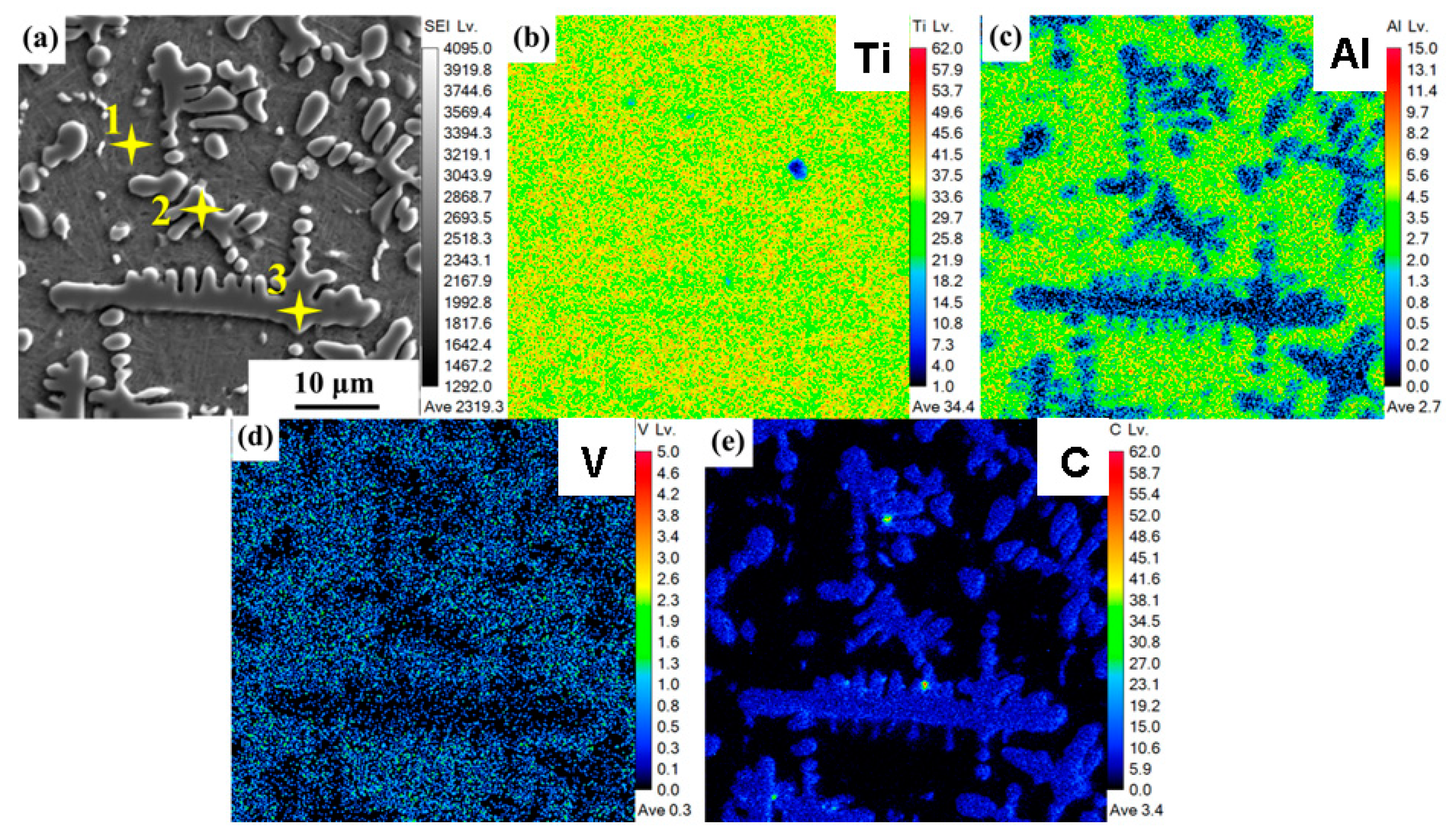
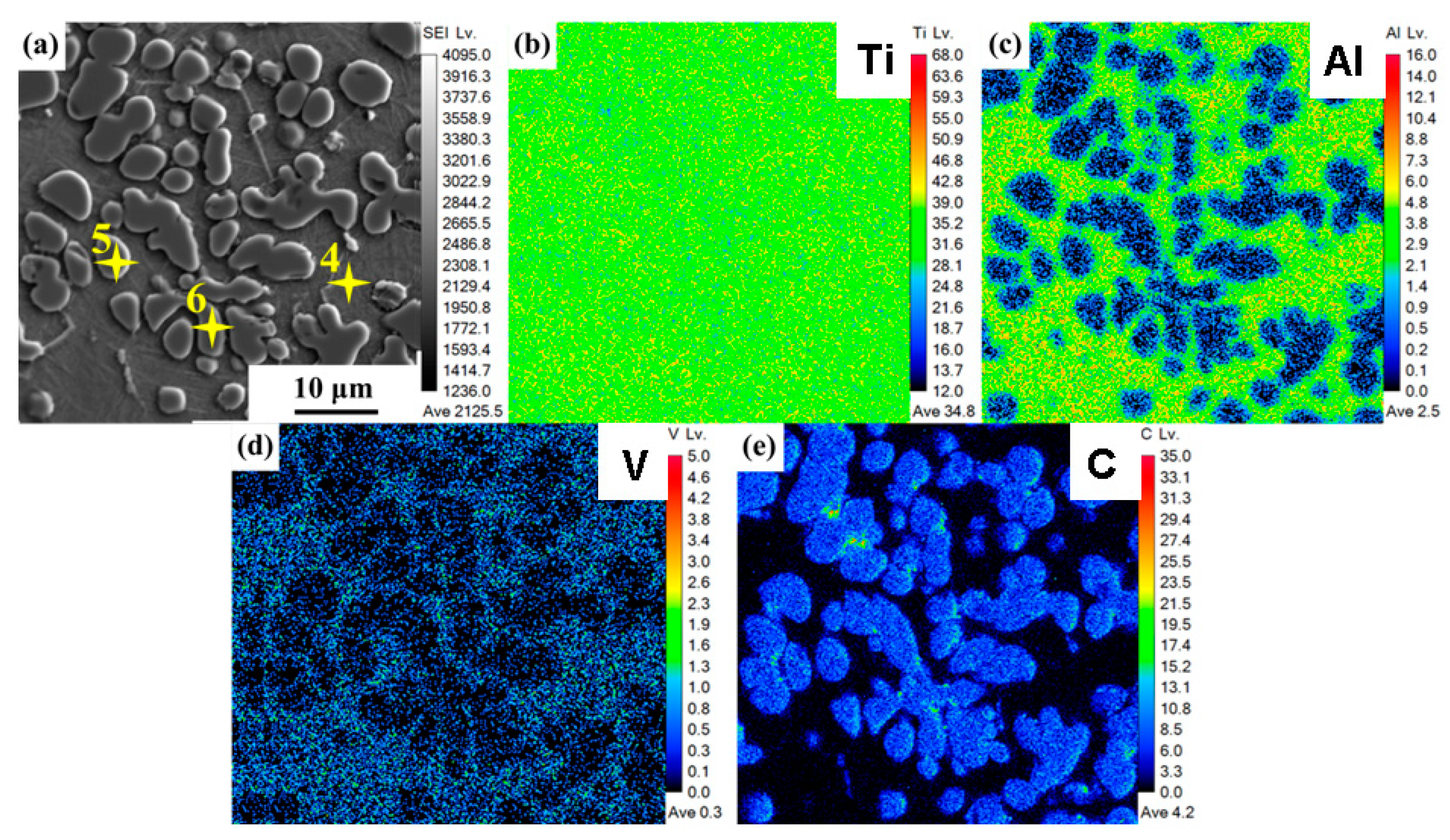
3.3. Elemental Distribution

The element distributions of the composite coating without ultrasonic action and with ultrasonic power of 1800 W are shown in Figure 11 and Figure 12, respectively. When there was no ultrasonic effect, the Al and V elements were uniformly distributed in the matrix, and there was no obvious compositional segregation. The C element was mainly distributed in the primary TiC, and there was also a small amount of the C element in the matrix to form an interstitial solid solution with the α-Ti. The Ti element was uniformly distributed in the matrix and primary TiC [29]. When the ultrasonic power was 1800 W, the distributions of the Al, V, C and Ti elements did not significantly change.
In order to study the influence of the ultrasonic action on the content of the C element in the primary TiC and matrix, the characteristic points were selected for quantitative analysis, and the analysis results are shown in Table 2. Both Point 1 and Point 4 are the matrix coatings of the composite materials, and the contents of the C element were 3.26 at.% and 3.23 at.%, respectively. It can be seen that the ultrasound did not cause significant changes in the content of the C element in the matrix. The same results also appeared in the dendritic primary TiC and granular primary TiC. When the ultrasonic power was 0 W and 1800 W, the contents of the C element in the dendritic primary TiC were 37.23 and 37.42 at.%, respectively, and the contents of the C element in the granular primary TiC were 36.19 and 36.54 at.%, respectively. It can be seen that the ultrasound did not have a significant impact on the content of the C element in the primary TiC and matrix during the solidification process of the molten pool.
When the ultrasonic power was 0 and 1800 W, the content of the C element in each phase did not significantly change. It can be seen from the element distribution diagram (Figure 11 and Figure 12) that the average contents of the Ti, Al and V in this region did not significantly change, but the average content of the C increased from 3.4 to 4.2. Therefore, more primary TiC was generated in the composite coating. The presence of more primary TiC per unit area will affect the hardness and wear resistance of materials.

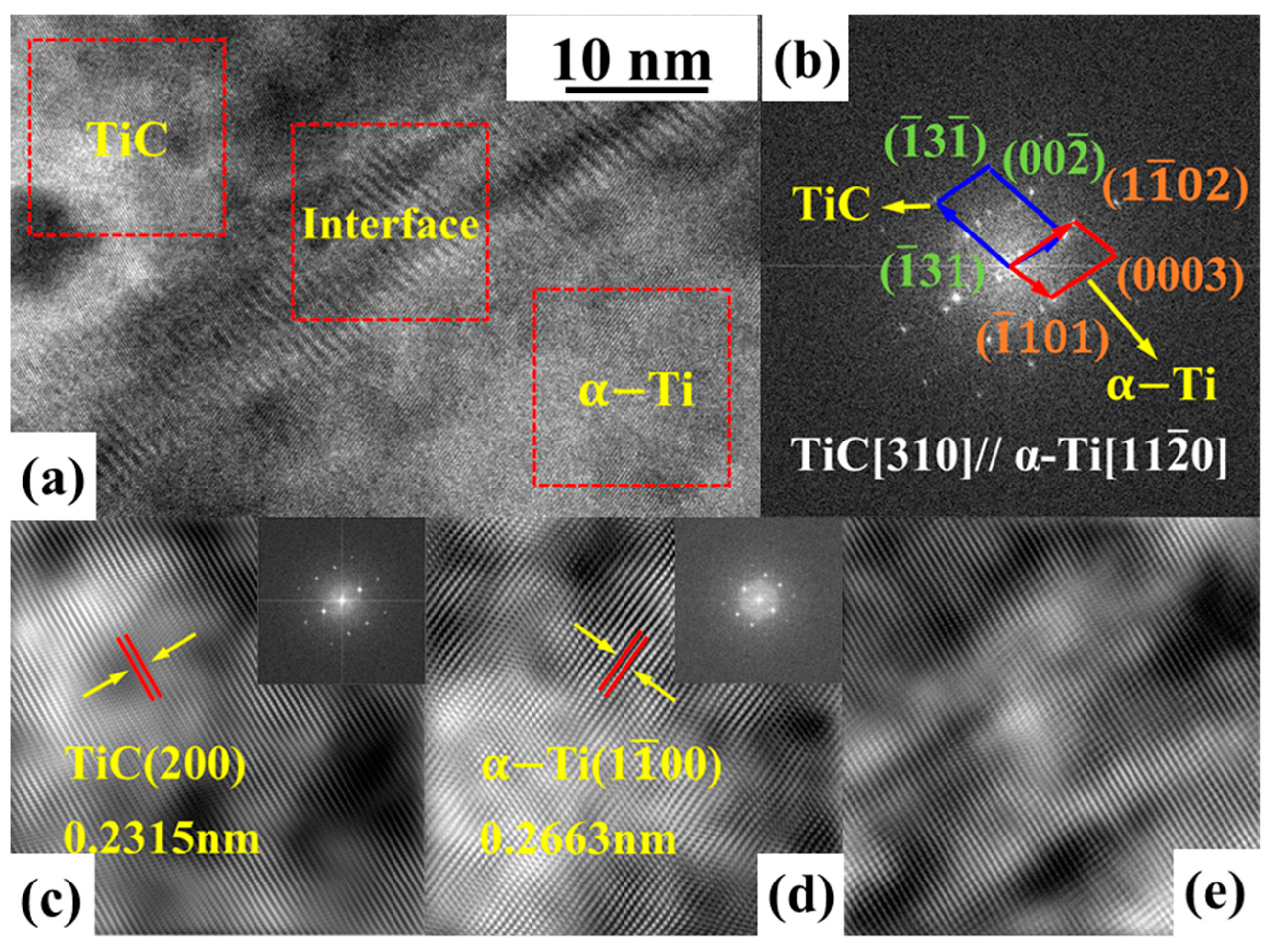
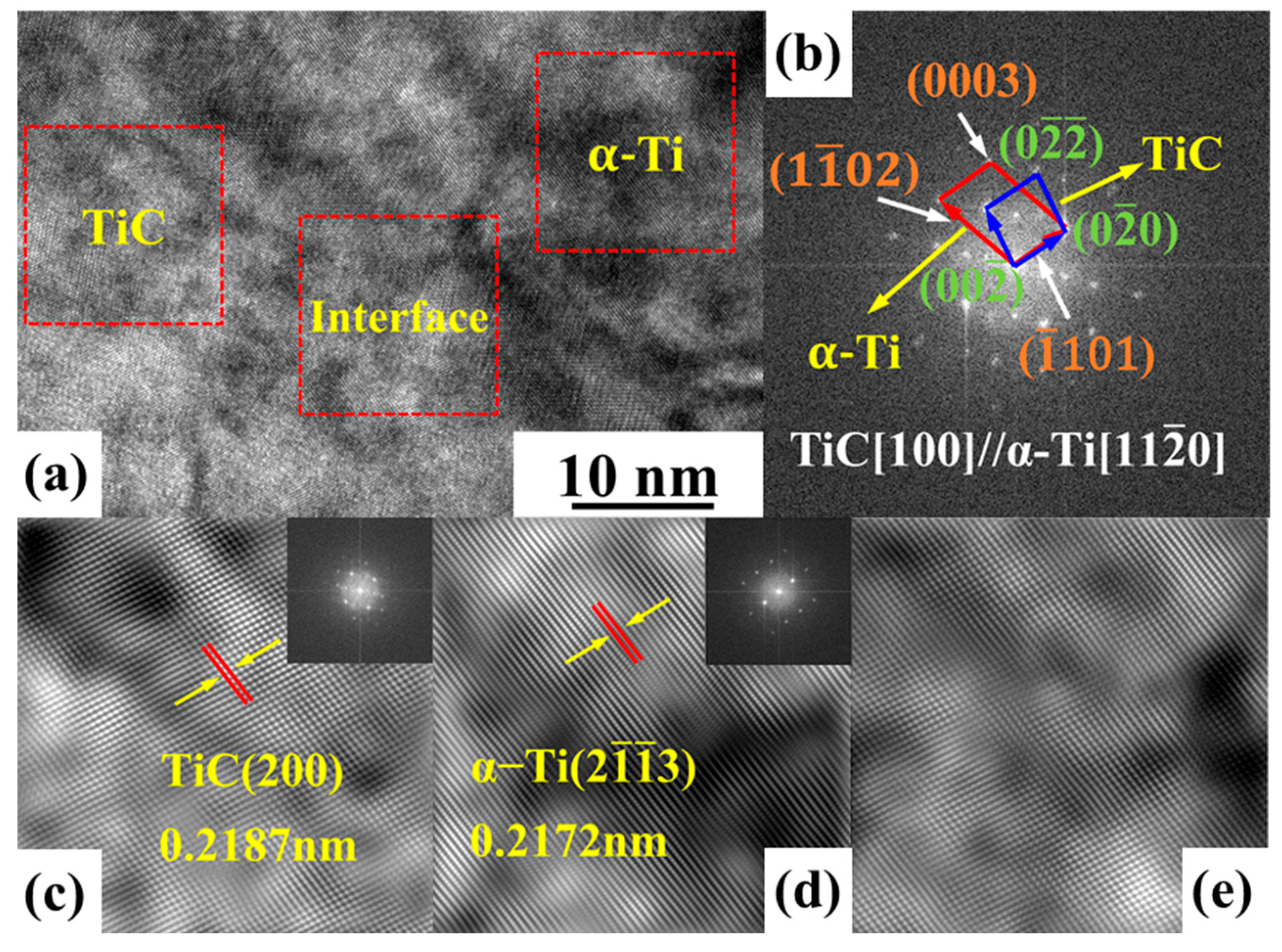
3.4. Interface Characteristics

The interface between the primary TiC and α-Ti when there was no ultrasound effect is shown in Figure 13a. There are no obvious cracks, pores or other defects at the interface. The fast Fourier transform of the interface between the primary TiC and α-Ti is shown in Figure 13a, and the obtained results are shown in Figure 13b. The orientation relationship between the primary TiC and α-Ti is [310]TiC// [ 11 2 ¯ 0 ] α-Ti and ( 00 2 ¯ ) TiC// ( 1 1 ¯ 02 ) α-Ti. The fast inverse Fourier transform was performed on the primary TiC phase, the α-Ti phase and the interface between them (Figure 13a), and the results are shown in Figure 13c–e. The interplanar spacing of the primary TiC ( 200 )   is about 0.2315 nm, and the interplanar spacing of the α-Ti ( 1 1 ¯ 00 ) is about 0.2663 nm. The lattice mismatch between the primary TiC phase and α-Ti is 15.03%, calculated by Formula (4) [30], which is a semicoherent phase boundary.
δ = / d α T i d T i C / d T i C
Among them,   d α T i and d T i C are the interplanar spacings of the α-Ti and TiC, respectively.
The interface between the primary TiC and α-Ti when the ultrasonic power was 1800 W is shown in Figure 14a. After the ultrasonic intervention, the binding interface was no longer as clear as that without the ultrasonic effect. The fast Fourier transform was performed on the interface, and the results are shown in Figure 14b. The orientation relationship between the primary TiC and α-Ti is [100]TiC// [ 11 2 ¯ 0 ] α-Ti and ( 0 2 ¯ 0 ) TiC// ( 1 ¯ 101 ) α-Ti. The inverse fast Fourier transform was performed on the primary TiC phase, the α-Ti phase and the interface between them, and the results are shown in Figure 14c–e. The primary TiC ( 200 ) interplanar spacing is 0.2187 nm, and the α-Ti ( 2 1 ¯ 1 ¯ 3 ) interplanar spacing is 0.2172 nm. According to Formula (4), the lattice mismatch of the two phases is 0.69%, which is a fully coherent phase boundary [30].

3.5. Mechanical Properties Analysis

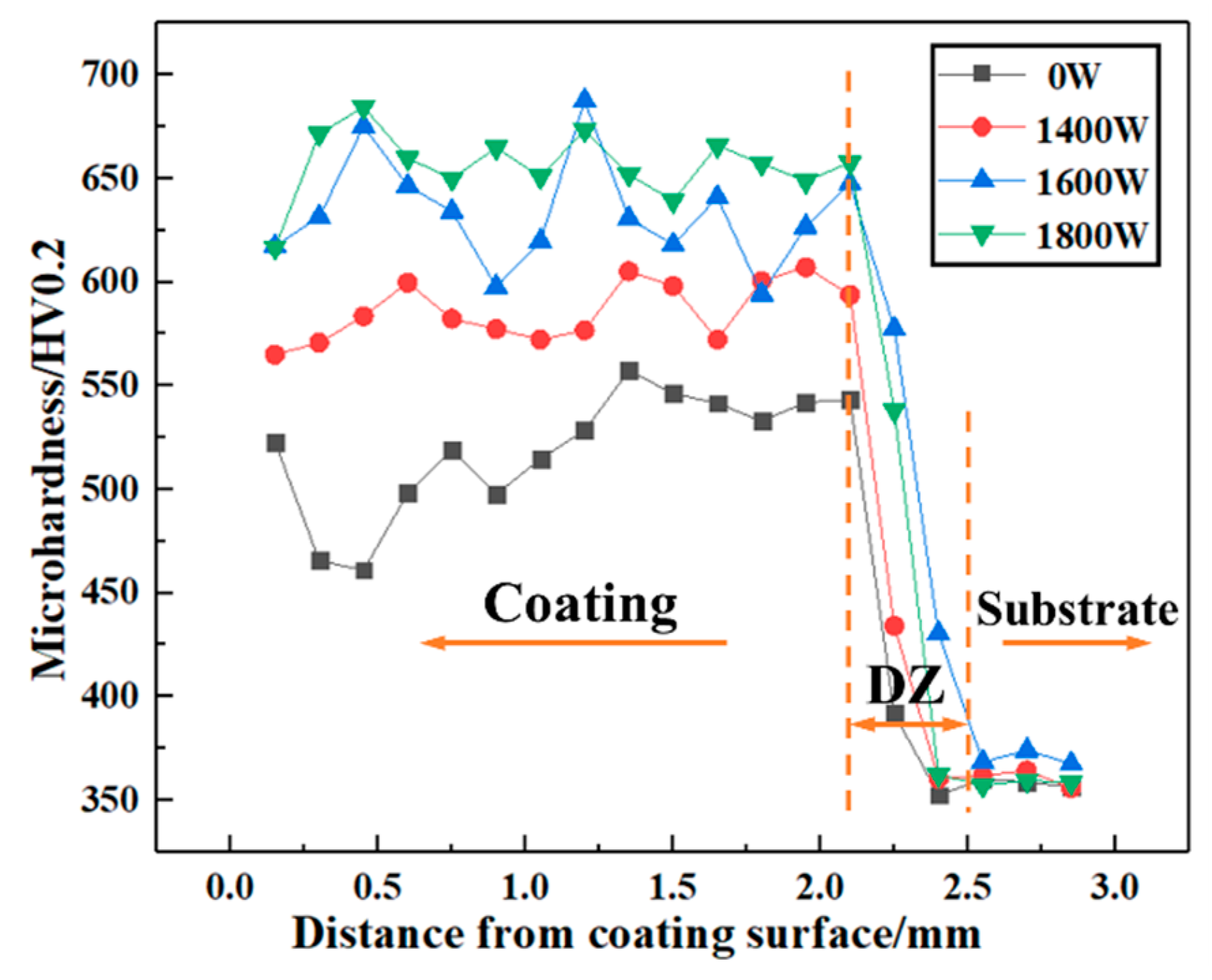
3.5.1. Microhardness Analysis

The microhardness distributions of the composite coating under different ultrasonic powers are shown in Figure 15. The microhardness of the composite coating fluctuated near its average value. With the decrease in the reinforcement, the microhardness of the bonding region gradually decreased, and the microhardness in the Ti6Al4V substrate was stable at 358 HV0.2. The results show that, when the ultrasonic power was 0 W, the average microhardness of the composite coating was 519.35 HV0.2. With the increase in the ultrasonic power, the average microhardness of the composite coating increased gradually. When the ultrasonic power was 1800 W, the average microhardness of the composite coating reached the highest value of 656.70 HV0.2, which was 83.21% higher than that of the Ti6Al4V substrate, and 26.44% higher than that of the composite coating without the ultrasonic effect.
Compared with the Ti6Al4V substrate, the microhardness of the composite coating was significantly improved, and mainly because the primary TiC and unmelted TiC particles exist in the composite coating in the form of a reinforcing phase, which plays the role of dispersion strengthening [21]. At the same time, the melting/dissolution of the TiC particles will cause the C element to be dissolved in the matrix, which results in lattice distortion, which plays a role in solid-solution strengthening [27]. With the increase in ultrasonic power, the average microhardness of the composite coating increases. This is mainly because the content of the primary TiC in the composite coating increases and the grain size decreases, which leads to the increase in the grain boundary per unit volume, which is conducive to increasing the plastic-deformation resistance of the composite coating and hindering the dislocation movement, thereby improving the microhardness of the composite coating [28,31].

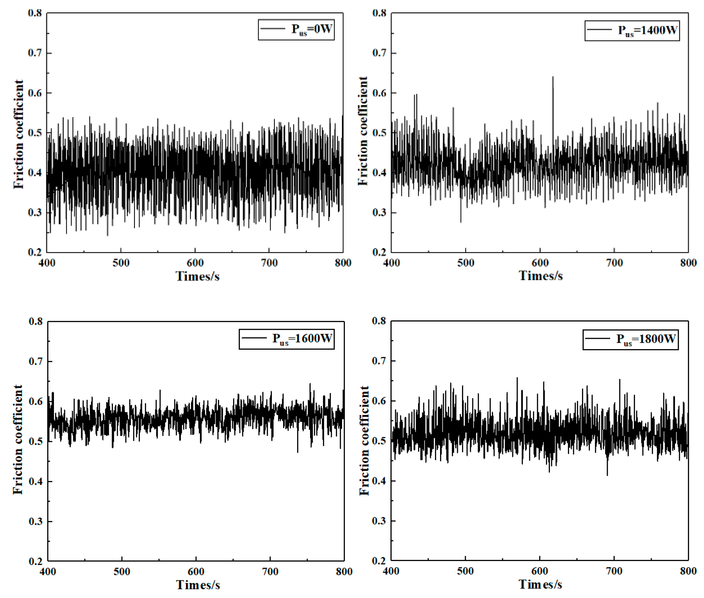
3.5.2. Friction and Wear Performance Analysis

The variation curve of the friction coefficient with time when the composite coatings prepared under different ultrasonic powers were in the stable wear stage is shown in Figure 16. When the ultrasonic power was 0 W, the friction coefficient fluctuated greatly with time, which is mainly because, when there is no ultrasonic effect, the content of the unmelted TiC particles in the composite coating is relatively high, which results in a large fluctuation of the friction coefficient. When these hard TiC particles are subjected to normal pressure, the instantaneous friction will also change rapidly. When the ultrasonic power is 1400 W, the fluctuation range of the friction coefficient decreases, but the friction coefficient still increases and decreases suddenly. When the ultrasonic power is 1600 W and 1800 W, the fluctuation amplitude of the friction coefficient decreases significantly, and it only shows slight fluctuation around the average friction coefficient.
The average friction coefficients of the composite coating under different ultrasonic powers are shown in Table 3. When no ultrasound is applied, due to the uneven distribution of the unmelted TiC, and during the friction process, the more frictional force that the unmelted TiC bears, the larger the size of the TiC that will be separated and peeled off. At this time, the friction pair needs to overcome the TiC. The bonding strength with the matrix makes the friction coefficient change greatly. With the increase in ultrasonic power, the average friction coefficient generally shows an upward trend. Due to the effect of ultrasonic waves, more unmelted TiC is melted/dissolved, and the distribution is more uniform. The friction pair mainly rubbed on the primary TiC. At the same time, the variation range of the friction coefficient was also smaller. However, affected by the random distribution of the unmelted TiC particles, when the ultrasonic power was 1800 W, the average friction coefficient was lower than that of the 1600 W ultrasonic power. When the ultrasonic power was 0 W, the friction coefficient of the composite coating was 0.426. When the ultrasonic power increased to 1600 W, the average friction coefficient of the composite coating reached the maximum of 0.570, which is 33.80% higher than that without the ultrasonic effect.
The friction and wear-surface morphology of the composite coating under different ultrasonic powers is shown in Figure 17. When the ultrasonic power was 0 W, there were a large number of weld-like blocks on the wear surface of the composite coating, as shown in Figure 17a. This is mainly because there were a large number of unmelted TiC particles in the composite coating. The edge shapes of these particles are irregular, there are sharp corners and protrusions, and the hardness is relatively high. In the friction process with the friction disc, the surface of the friction disc is cut, and the generated debris is squeezed and deformed over a long period of friction. Some debris will adhere to the surface of the composite coating, thus forming more weld-like blocks. Therefore, the wear mechanism of the composite coating without ultrasonic action is mainly abrasive wear.
When the ultrasonic power was 1400 W, the number of weld-like blocks on the wear surface of the composite coating was significantly reduced, and some parallel furrows began to appear. The widths and depths of these parallel furrows were relatively large, as shown in Figure 17b. The decrease in the weld-like blocks was mainly due to the decrease in the number of unmelted TiC particles in the composite coating with the addition of the ultrasonic energy field. The formation of furrows was mainly due to the fact that some unmelted TiC particles were separated from the composite coating to form abrasive particles in the friction and wear process. These fine unmelted TiC particles generate secondary scratches on the surface of the composite coating, thus forming some furrows with large widths and depths on the surface of the composite coating. At this time, the wear mechanism is mainly abrasive wear, and there is a small amount of adhesive wear.
When the ultrasonic power reached 1600 and 1800 W, the weld-like blocks on the wear surface of the composite coating almost disappeared, and the furrow characteristics became more obvious. At this time, the number of parallel furrows increased, and the widths and depths decreased, as shown in Figure 17c,d. On the one hand, the increase in ultrasonic power reduced the number of unmelted TiC particles in the composite coating and the number of unmelted TiC particles separated from the composite coating, which thus reduced the number of abrasive particles. On the other hand, the number of primary TiC increased, the size decreased and the distribution was more uniform in the matrix, which is beneficial to improve the ability of the composite coating to resist ploughing deformation. When the primary TiC and No. 45 were directly cut, the shedding debris was squeezed and deformed during wear, and it adhered to the friction surface. At this time, the wear mechanism of the composite coating was mainly adhesive wear.

4. Conclusions

In this paper, a follow-up ultrasonic-assisted laser-additive-manufacturing method is proposed that uses the cavitation effect, acoustic-streaming effect and thermal effect of ultrasound to intervene in the melting and solidification behavior of the melt pool in real time, and the effect of the ultrasound on the microstructure and mechanical properties of TiC-reinforced Ti6Al4V composite coatings was investigated. The main conclusions are as follows:
(1)
Cavitation bubbles generated by the ultrasonic-cavitation effect will produce instantaneous high temperature and high pressure when they break. On the one hand, the temperature of the molten pool is increased, and the content of the unmelted TiC is decreased. On the other hand, the primary TiC in the melting process is broken by high pressure, and the distribution uniformity of the primary TiC is improved by the acceleration of the flow of the molten pool under the effect of ultrasonic acoustic streaming. When the ultrasonic power was 1800 W, the content of the unmelted TiC in the composite coating decreased significantly, and was only 50.23% of that without ultrasound;
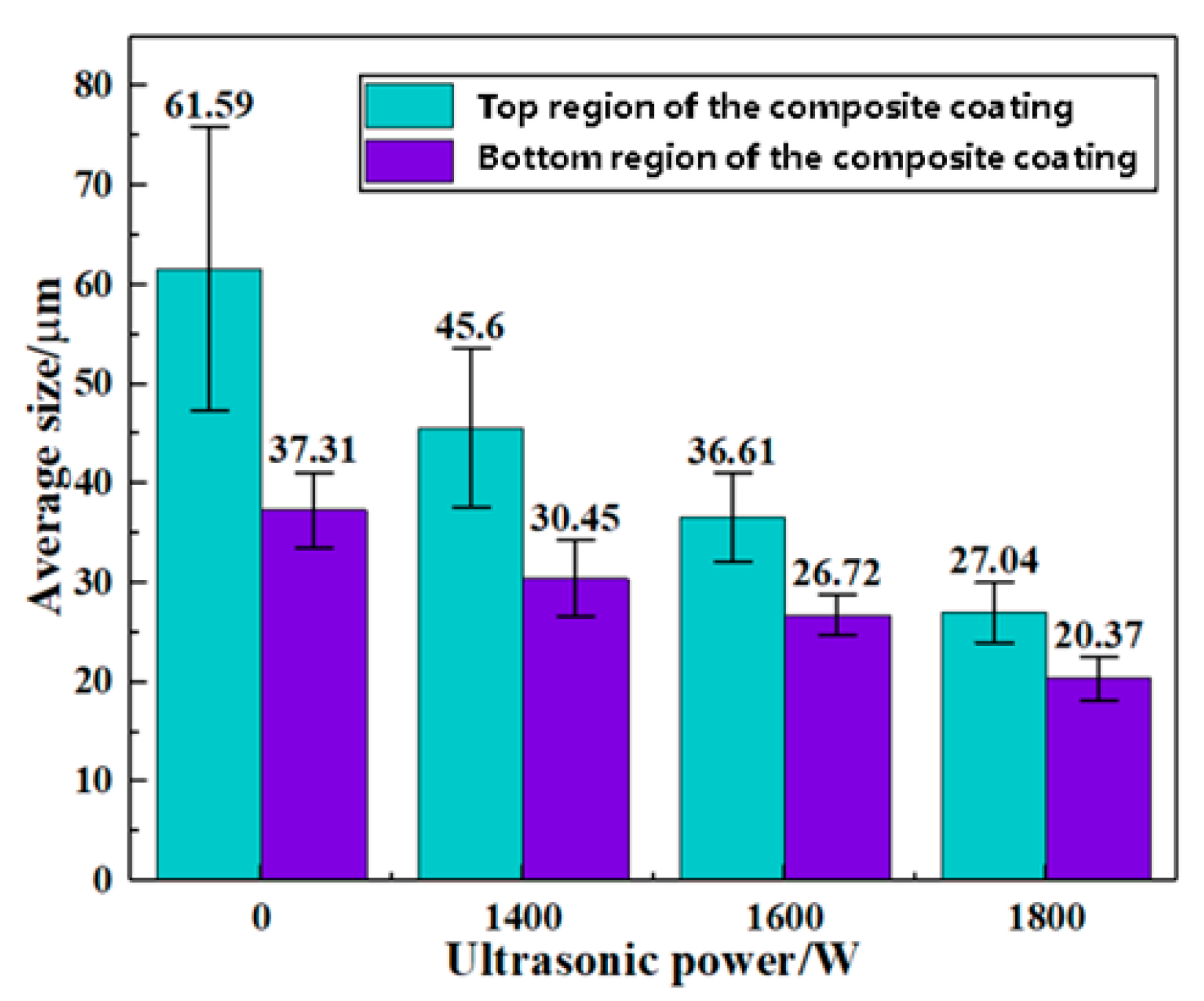
(2)
The average size of the dendritic primary TiC in the high-temperature-gradient region of the composite coating decreased from 61.59 to 27.04 μm under ultrasound, which is 56.10% lower than that without ultrasound. The grain size of the α-Ti in the matrix is also affected by ultrasonic power, but there is no obvious change rule. At the same time, the addition of an ultrasonic energy field helps to improve the bonding interface between the primary TiC and α-Ti phases. The lattice mismatch between the primary TiC and α-Ti decreased from 15.03% to 0.69% under 1800 W ultrasonic power, which helped to improve the bonding strength of the primary TiC and α-Ti;
(3)
With the increase in ultrasonic power, the average microhardness of the composite coating increased. When the ultrasonic power was 1800 W, the average microhardness of the composite coating reached the highest value of 656.70 HV0.2, which is 83.21% higher than that of Ti6Al4 V, and 26.44% higher than that without ultrasound. The strengthening mechanism was mainly the TiC-dispersion strengthening and solid-solution strengthening of the C element;
(4)
The friction and wear properties of composite coatings are also affected by ultrasonic power. With the increase in ultrasonic power, the fluctuation range of the friction coefficient of the composite coatings decreases with time, while the average friction coefficient increases, and the wear mechanism changes from abrasive wear to adhesive wear.

Author Contributions

Conceptualization, G.M.; Data curation, G.M.; Formal analysis, Y.L.; Funding acquisition, F.N. and G.M.; Investigation, X.Y.; Methodology, Y.L.; Project administration, D.W.; Software, C.S.; Supervision, D.W.; Validation, Z.Z.; Visualization, C.S.; Writing—original draft, Y.L.; Writing—review & editing, F.N. All authors have read and agreed to the published version of the manuscript.

Funding

The authors are grateful for the financial support from the National Natural Science Foundation of China (No. 52175291), and the Fundamental Research Funds for the Central Universities (DUT21YG116).

Institutional Review Board Statement

Not applicable.

Informed Consent Statement

Not applicable.

Data Availability Statement

The authors confirm that the data supporting the findings of this study are available within the article.

Conflicts of Interest

The authors declare that they have no known competing financial interests or personal relationships that could have appeared to influence the work reported in this paper.

References

  1. Zhang, Z.Q.; Yang, F.; Zhang, T.G.; Zhang, H.W.; Zhang, D.L. Research progress of laser cladding titanium carbide reinforced titanium-based composite coating. Surf. Technol. 2020, 49, 138–151. [Google Scholar]
  2. Xing, Y.Z.; Jiang, C.P.; Hao, J.M. Time dependence of microstructure and hardness in plasma carbonized Ti-6A1-4V alloys. Vacuum 2013, 95, 12–17. [Google Scholar] [CrossRef]
  3. Xiao, L.; Tian, S.G.; Bao, X.Y.; Chen, L.Q. Creep properties and effect factors of hot continuous rolled Ti-6Al-4V alloy. Mater. Sci. Eng. A 2011, 526, 452–458. [Google Scholar]
  4. Hao, Y.J.; Liu, J.X.; Li, J.C.; Li, S.; Zou, Q.; Chen, X. Rapid preparation of TiC reinforced Ti6Al4V based composites by carburizing method through spark plasma sintering technique. Mater. Des. 2015, 65, 94–97. [Google Scholar] [CrossRef]
  5. Nemati, A.; Saghafi, M.; Khamseh, S.; Alibakhshi, E.; Zarrintaj, P.; Saeb, M.R. Magnetron-sputtered TixNy thin films applied on titanium based alloys for biomedical applications: Composition-microstructure-property relationships. Surf. Coat. Technol. 2018, 349, 251–259. [Google Scholar] [CrossRef]
  6. Chen, C.Y.; Deng, Q.L.; Song, J.L. The effect of Ultrasonic Vibration on Laser Cladding Process. Electromech. Mould. 2005, 37–39. [Google Scholar]
  7. Cong, W.L.; Ning, F.D. A fundamental investigation on ultrasonic vibration-assisted laser engineered net shaping of stainless steel. Int. J. Mach. Tool Manufact. 2017, 121, 61–69. [Google Scholar] [CrossRef]
  8. Wang, Y.L.; Liu, S.Y.; Zhang, X.Y.; Liu, Y.; Li, R. Experiments and analyses of 3540Fe/CeO2 coatings by ultrasonic vibration assisted laser cladding. China Mech. Eng. 2018, 29, 84–89. [Google Scholar] [CrossRef]
  9. Ning, F.D.; Cong, W.L. Microstructures and mechanical properties of Fe-Cr stainless steel parts fabricated by ultrasonic vibration-assisted laser engineered net shaping process. Mater. Lett. 2016, 179, 61–64. [Google Scholar] [CrossRef]
  10. Li, M.Y.; Zhang, Q.; Han, B.; Song, L.; Cui, G.; Yang, J.; Li, J. Microstructure and property of Ni/WC/La2O3 coatings by ultrasonic vibration-assisted laser cladding treatment. Opt. Lasers Eng. 2020, 125, 105848. [Google Scholar] [CrossRef]
  11. Fallah, V.; Corbin, S.F.; Khajepour, A. Process optimization of Ti–Nb alloy coatings on a Ti–6Al–4V plate using a fiber laser and blended elemental powders. J. Mater. Process. Technol. 2010, 210, 2081–2087. [Google Scholar] [CrossRef]
  12. Wu, X.W.; Zhu, B.D.; Zeng, X.Y.; Hu, X.; Cui, K. Critical state of laser cladding with powder auto-feeding. Surf. Coat. Technol. 1996, 79, 200–204. [Google Scholar] [CrossRef]
  13. Zhou, S.F.; Dai, X.G.; Zeng, X.Y. Effects of processing parameters on structure of Ni-based WC composite coatings during laser induction hybrid rapid cladding. Appl. Surf. Sci. 2009, 255, 8494–8500. [Google Scholar] [CrossRef]
  14. Liu, X.C.; Wu, C.S.; Padhy, G.K. Characterization of plastic deformation and material flow in ultrasonic vibration enhanced friction stir welding. Scr. Mater. 2015, 102, 95–98. [Google Scholar] [CrossRef]
  15. Ya, B.; Zhou, B.W.; Yang, H.S.; Huang, B.; Jia, F.; Zhang, X. Microstructure and mechanical properties of in situ casting TiC/Ti6Al4V composites through adding multi-walled carbon nanotubes. J. Alloys Compd. 2015, 637, 456–460. [Google Scholar] [CrossRef]
  16. Ma, G.Y.; Yu, C.; Tang, B.K.; Li, Y.; Niu, F.; Wu, D.; Bi, G.; Liu, S. High-mass-proportion TiCp/Ti6Al4V titanium matrix composites prepared by directed energy deposition. Addit. Manuf. 2020, 35, 101323. [Google Scholar] [CrossRef]
  17. Liu, S.N.; Liu, Z.D.; Wang, Y.; Yue, P. Ti-based composite coatings with gradient TiCx reinforcements on Ti6Al4V titanium alloy prepared by laser cladding. Sci. China Technol. Sci. 2014, 57, 1454–1461. [Google Scholar] [CrossRef]
  18. Wu, D.J.; Song, C.C.; Di, T.D.; Niu, F.; Ma, G. Intermetallic regulation mechanism of inconel 718/Ti6Al4V composite by novel follow-up ultrasonic assisted laser additive manufacturing. Compos. Part B Eng. 2022, 235, 109736. [Google Scholar] [CrossRef]
  19. Li, L.Q.; Wang, J.D.; Lin, P.P.; Liu, H. Microstructure and mechanical properties of functionally graded TiCp/Ti6Al4V composite fabricated by laser melting deposition. Ceram. Int. 2017, 43, 16638–16651. [Google Scholar] [CrossRef]
  20. Liu, H.D.; Hu, F.Y.; Cui, A.Y.; Li, H. Experimental on thermal cycle of laser welding with ultrasonic processing across different phases. Trans. China Weld. Inst. 2015, 36, 13–17. [Google Scholar]
  21. Weng, F.; Yu, H.J.; Chen, C.Z.; Liu, J.; Zhao, L. Microstructures and properties of TiN reinforced Co-based composite coatings modified with Y2O3 by laser cladding on Ti–6Al–4V alloy. J. Alloys Compd. 2015, 650, 178–184. [Google Scholar] [CrossRef]
  22. Su, Y.Y.; Wang, Z.F.; Lu, H.F.; Luo, K.; Lu, J. Improved wear resistance of directed energy deposited Fe-Ni-Cr alloy via closed-loop controlling laser power. J. Manuf. Process. 2022, 75, 802–813. [Google Scholar] [CrossRef]
  23. Xu, X.; Lu, H.F.; Qin, J.X.; Luo, K.; Su, Y.; Xing, F.; Lu, J. High-speed-rate direct energy deposition of Fe-based stainless steel: Process optimization, microstructural features, corrosion and wear resistance. J. Manuf. Process. 2022, 75, 243–258. [Google Scholar] [CrossRef]
  24. Braschkin, V.V.; Popova, S.V. The formation, structure and thermal stability of the amorphous alloy Cu0.85Sn0.15 obtained by high pressure treatment. J. Less Common Met. 1988, 138, 39–45. [Google Scholar] [CrossRef]
  25. Li, J.Y.; Zhao, G.Z.; Wu, S.S.; Huang, Z.; Lü, S.; Chen, Q.; Li, F. Preparation of hybrid particulates SiCnp and Mg2Si reinforced Al-Cu matrix composites. Mater. Sci. Eng. A 2019, 751, 107–114. [Google Scholar] [CrossRef]
  26. Fruhauf, J.B.; Roger, J.; Dezellus, O.; Gourdet, S.; Karnatak, N.; Peillon, N.; Saunier, S.; Montheillet, F.; Desrayaud, C. Microstructural and mechanical comparison of Ti+15%TiCp composites prepared by free sintering, HIP and extrusion. Mater. Sci. Eng. A 2012, 554, 22–32. [Google Scholar] [CrossRef]
  27. Ochonogor, O.F.; Meacock, C.; Abdulwahab, M.; Pityana, S.; Popoola, A.P.I. Effects of Ti and TiC ceramic powder on laser-cladded Ti–6Al–4V in situ intermetallic composite. Appl. Surf. Sci. 2012, 263, 591–596. [Google Scholar] [CrossRef]
  28. Vasanthakumar, K.; Bakshi, S.R. Effect of C/Ti ratio on densification, microstructure and mechanical properties of TiCx prepared by reactive spark plasma sintering. Ceram. Int. 2018, 44, 484–494. [Google Scholar] [CrossRef]
  29. Dong, S.Y.; Ma, Y.Z.; Xu, B.S.; Han, W.Z. Current Status of Material for Laser Cladding. Mater. Rep. 2006, 20, 5–9. [Google Scholar]
  30. Luo, X.; Li, J.; Li, G.J. Effect of NiCrBSi content on microstructural evolution, cracking susceptibility and wear behaviors of laser cladding WC/Ni–NiCrBSi composite coatings. J. Alloys Compd. 2015, 626, 102–111. [Google Scholar] [CrossRef]
  31. Lu, H.F.; Xue, K.N.; Xu, X.; Luo, K.Y.; Xing, F.; Yao, J.H.; Lu, J.Z. Effects of laser shock peening on microstructural evolution and wear property of laser hybrid remanufactured Ni25/Fe104 coating on H13 tool steel. J. Mater. Process. Tech. 2021, 291, 117016. [Google Scholar] [CrossRef]
Figure 1. Morphology of the mixed powder: (a) low magnification; (b) high magnification.
Coatings 12 00986 g001
Figure 2. Schematic diagram of the follow-up ultrasonic-assisted laser-additive-manufacturing system.
Coatings 12 00986 g002
Figure 3. XRD spectrum of 30 wt.% TiC/Ti6Al4V composite coating.
Coatings 12 00986 g003
Figure 4. Cross-sectional morphology of the composite coating: (a) Pus = 0 W; (b) Pus = 1400 W; (c) Pus = 1600 W; (d) Pus = 1800 W.
Coatings 12 00986 g004
Figure 5. Effect of ultrasonic power for unmelted TiC content.
Coatings 12 00986 g005
Figure 6. Morphology and size of dendritic primary TiC at the bottom of the composite coating: (a) Pus = 0 W; (b) Pus = 1400 W; (c) Pus = 1600 W; (d) Pus = 1800 W.
Coatings 12 00986 g006
Figure 7. Morphology and size of dendritic primary TiC at the top of the composite coating: (a) Pus = 0 W; (b) Pus = 1400 W; (c) Pus = 1600 W; (d) Pus = 1800 W.
Coatings 12 00986 g007
Figure 8. Average sizes of dendritic primary TiC in different regions of the composite coating.
Coatings 12 00986 g008
Figure 9. Effect of ultrasound on dendritic primary TiC: (a) Pus = 0 W; (b) Pus = 1800 W.
Coatings 12 00986 g009
Figure 10. IPF diagrams for the middle of the composite coating. (a) Pus = 0 W; (b) Pus = 1400 W; (c) Pus = 1600 W; (d) Pus = 1800 W.
Coatings 12 00986 g010
Figure 11. Element distributions of composite coating without ultrasound: (a) 30 wt.% TiC/Ti6Al4V; (b) Ti; (c) Al; (d) V; (e) C.
Coatings 12 00986 g011
Figure 12. Element distributions of composite coating at 1800 W ultrasonic power: (a) 30 wt.% TiC/Ti6Al4V; (b) Ti; (c) Al; (d) V; (e) C.
Coatings 12 00986 g012
Figure 13. Bonding interface between primary TiC and α-Ti without ultrasonic effect: (a) HRTEM at the interface; (b) SAED of TiC and α-Ti; (c) Fast Fourier inverse image corresponding to TiC; (d) Fast Fourier inverse image corresponding to α-Ti; (e) The corresponding inverse fast Fourier image at the interface.
Coatings 12 00986 g013
Figure 14. Bonding interface between primary TiC and α-Ti at ultrasonic power of 1800 W: (a) HRTEM at the interface; (b) SAED of TiC and α-Ti; (c) Fast Fourier inverse image corresponding to TiC; (d) Fast Fourier inverse image corresponding to α-Ti; (e) The corresponding inverse fast Fourier image at the interface.
Coatings 12 00986 g014
Figure 15. Microhardness distributions of composite coating and substrate.
Coatings 12 00986 g015
Figure 16. The friction-coefficient curves of composite coating with time.
Coatings 12 00986 g016
Figure 17. Friction and wear-surface morphology of composite coatings: (a) Pus = 0 W; (b) Pus = 1400 W; (c) Pus = 1600 W; (d) Pus = 1800 W.
Coatings 12 00986 g017
Table 1. Average grain sizes of α-Ti.
Ultrasonic Power/W0140016001800
Average grain size of α-Ti/μm0.840.731.060.75
Table 2. Element analysis results for corresponding positions in Figure 11 and Figure 12.
PointsAl-Ti-V-C-
-wt.%at.%wt.%at.%wt.%at.%wt.%at.%
16.3910.5288.8182.334.463.880.883.26
20.460.5689.3162.371.330.8712.9936.19
30.380.4787.9061.501.210.7913.3437.23
47.1311.6188.7381.354.423.810.883.23
50.340.4288.0962.151.330.8812.9836.54
60.350.4388.1761.510.970.6413.4537.42
Table 3. Average friction coefficients of composite coating.
Ultrasonic Power/W0140016001800
Average friction coefficients of composite coatings0.4260.4350.5700.529
Publisher’s Note: MDPI stays neutral with regard to jurisdictional claims in published maps and institutional affiliations.

