
Fabrication of Efficient Gold−Nickel-Supported Titania Nanotube Electrocatalysts for Sodium Borohydride−Hydrogen Peroxide Fuel Cells


 ,
,  and
and
Abstract
:1. Introduction
2. Materials and Methods
2.1. Chemicals
2.2. Fabrication of Catalysts
2.3. Physical Characterization
2.4. Electrochemical Measurements
2.5. Fuel Cell Test Experiments
3. Results and Discussion
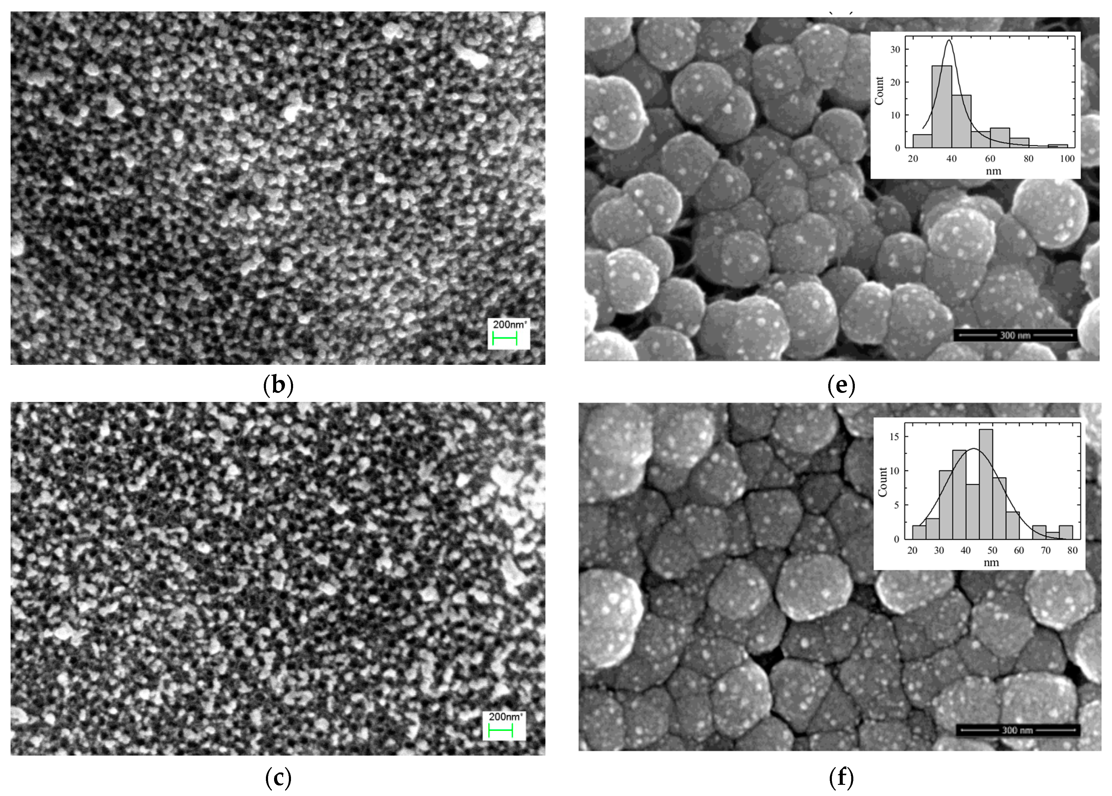
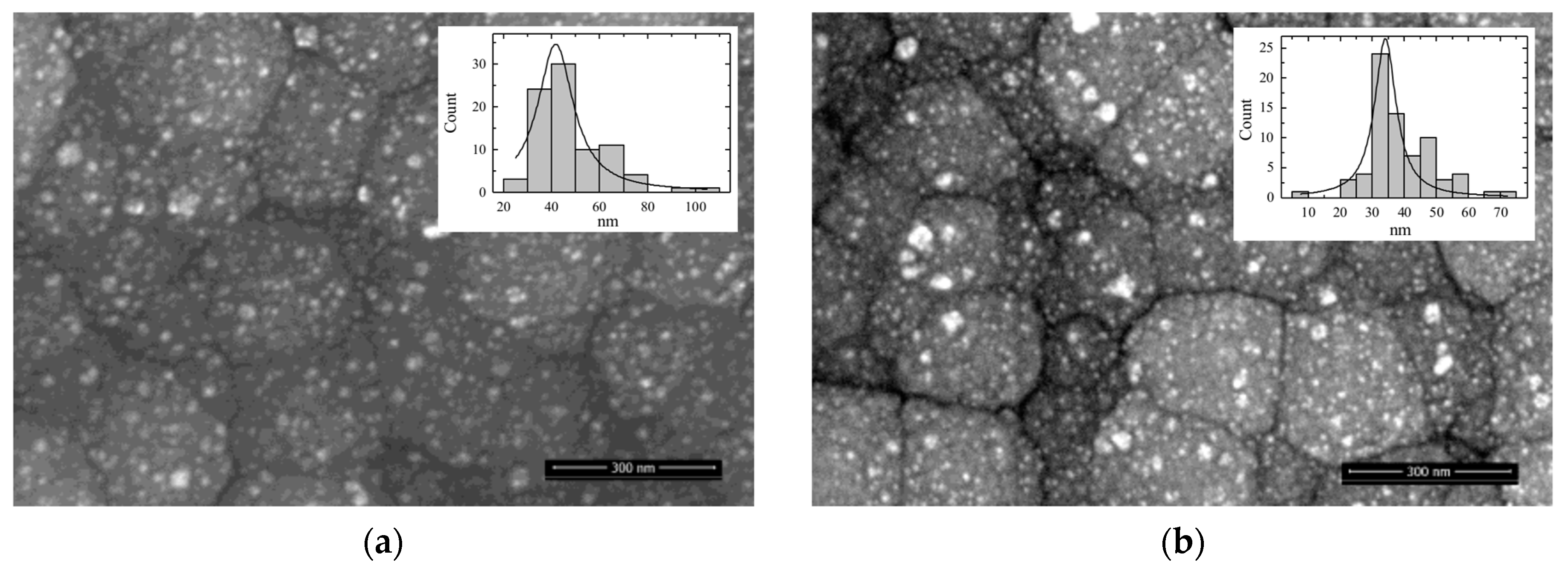
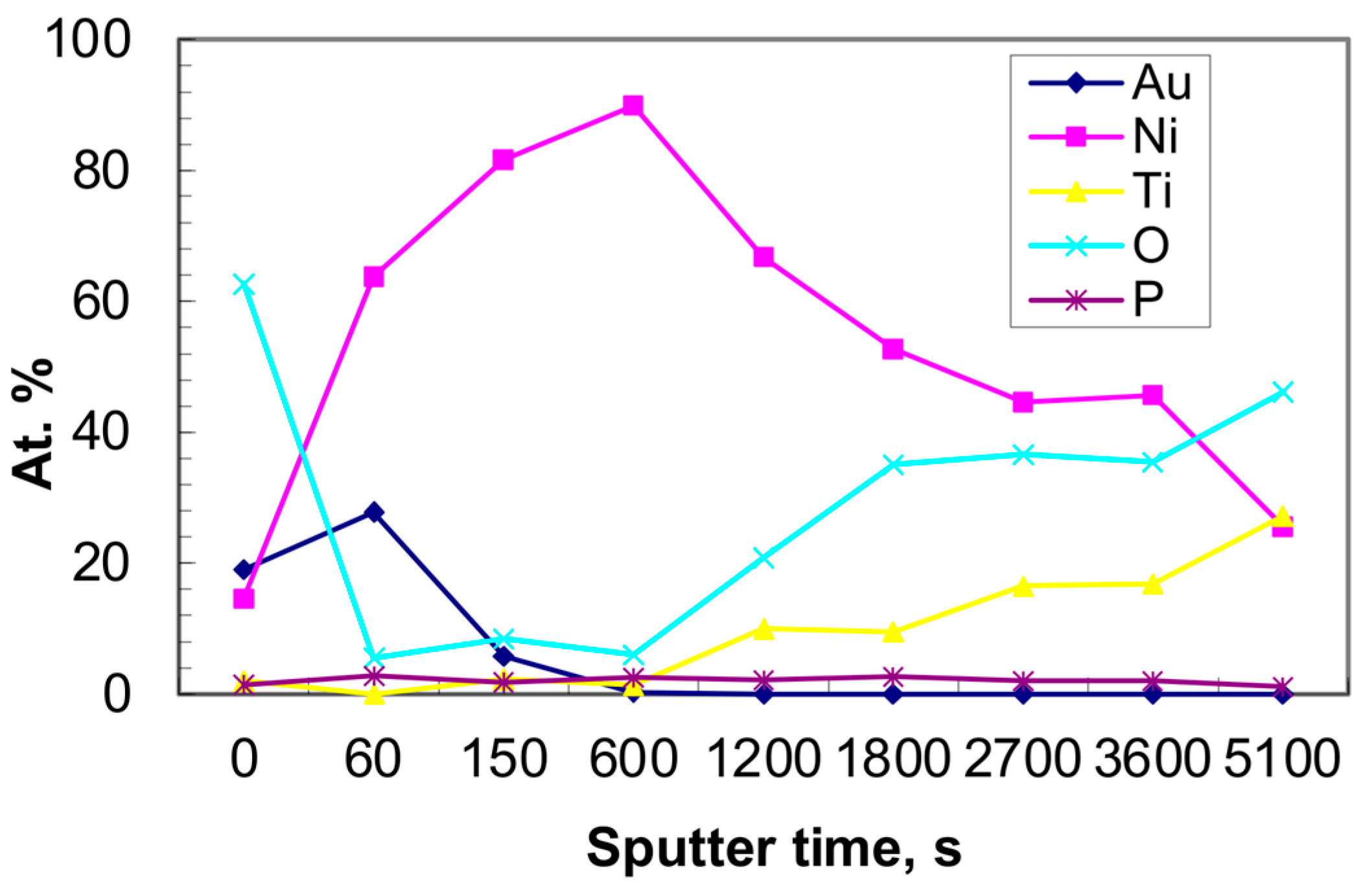
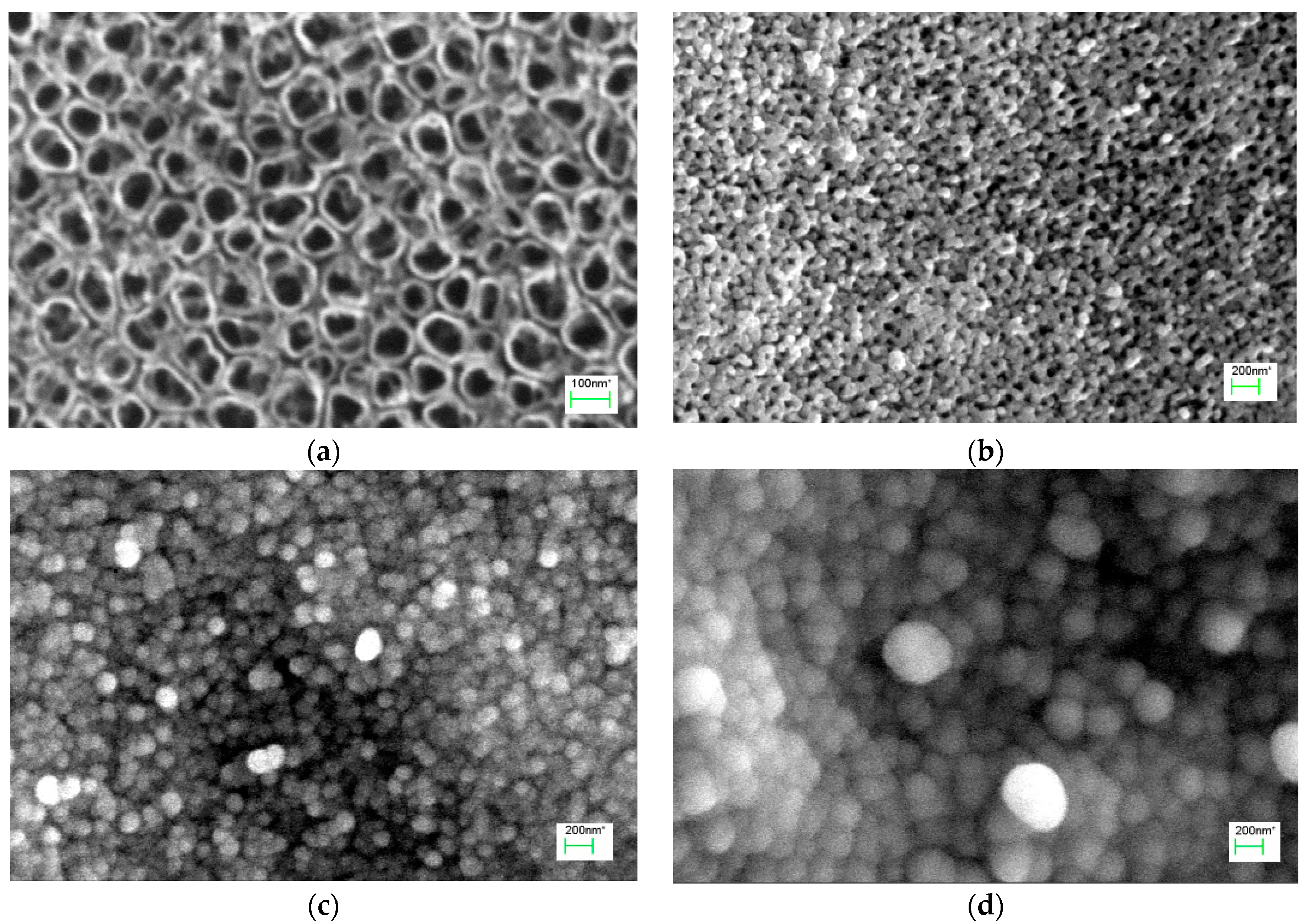
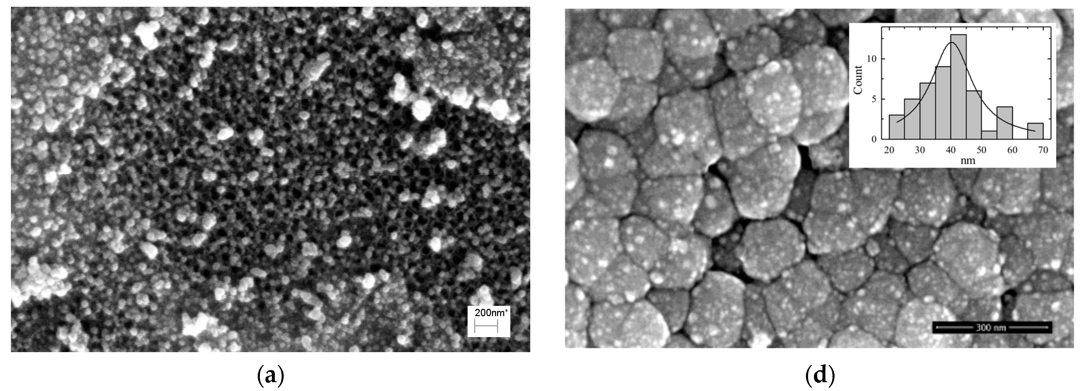
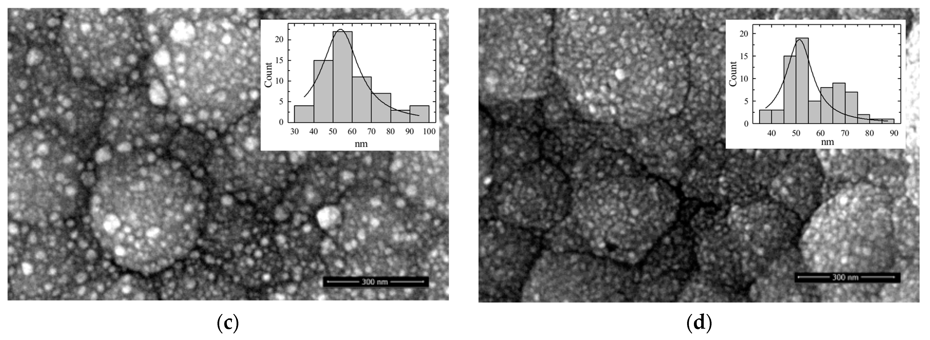
3.1. Morphology of Catalysts
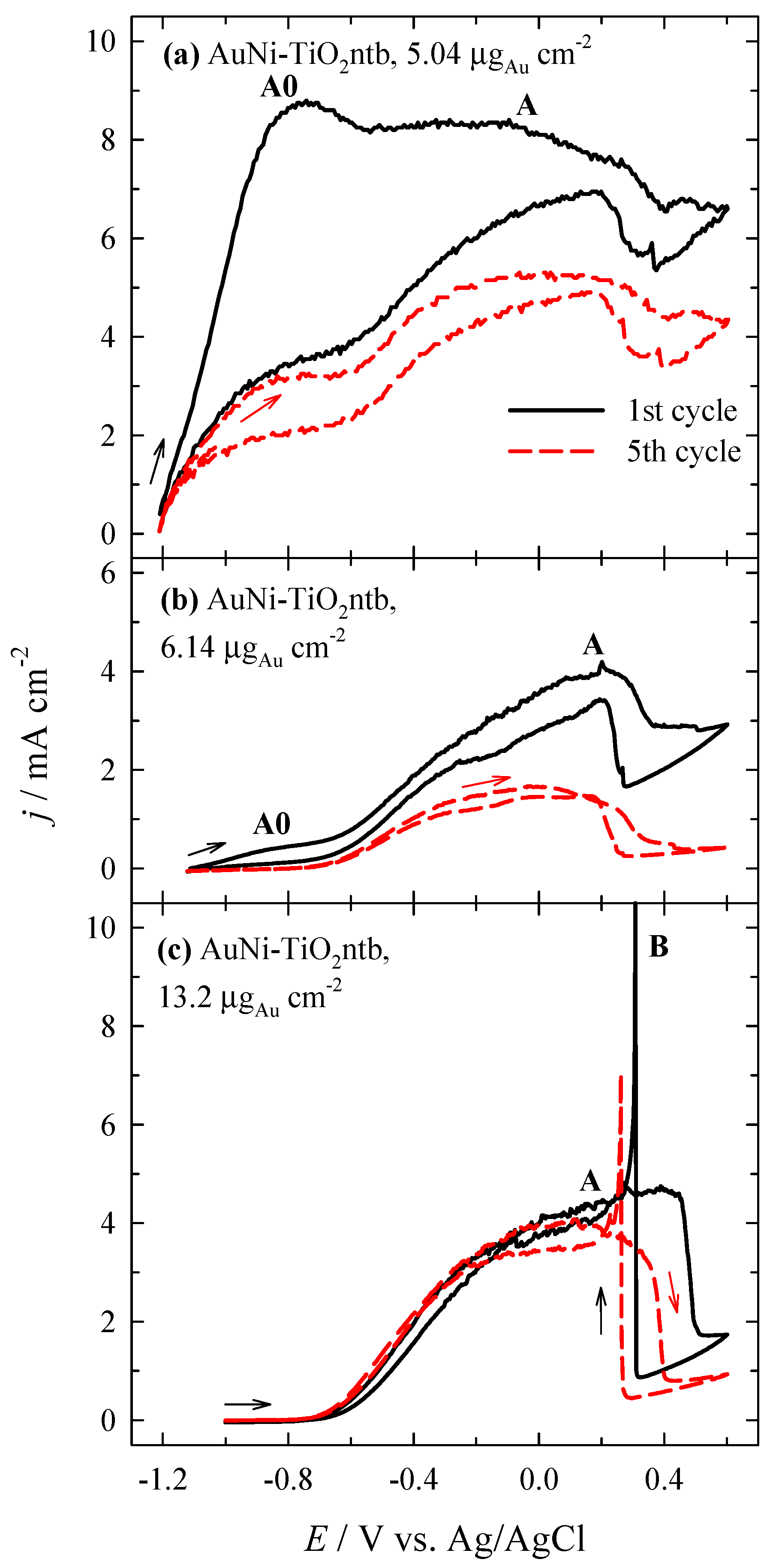
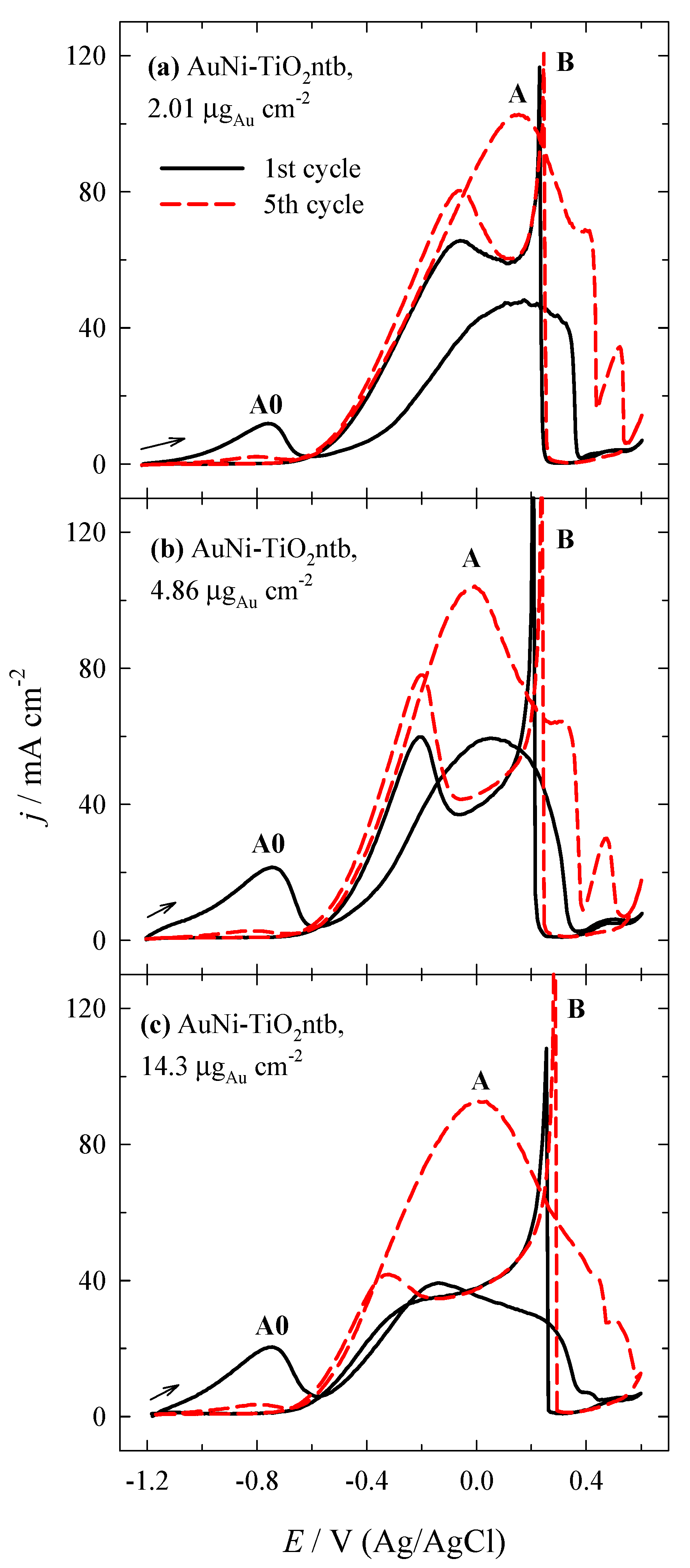
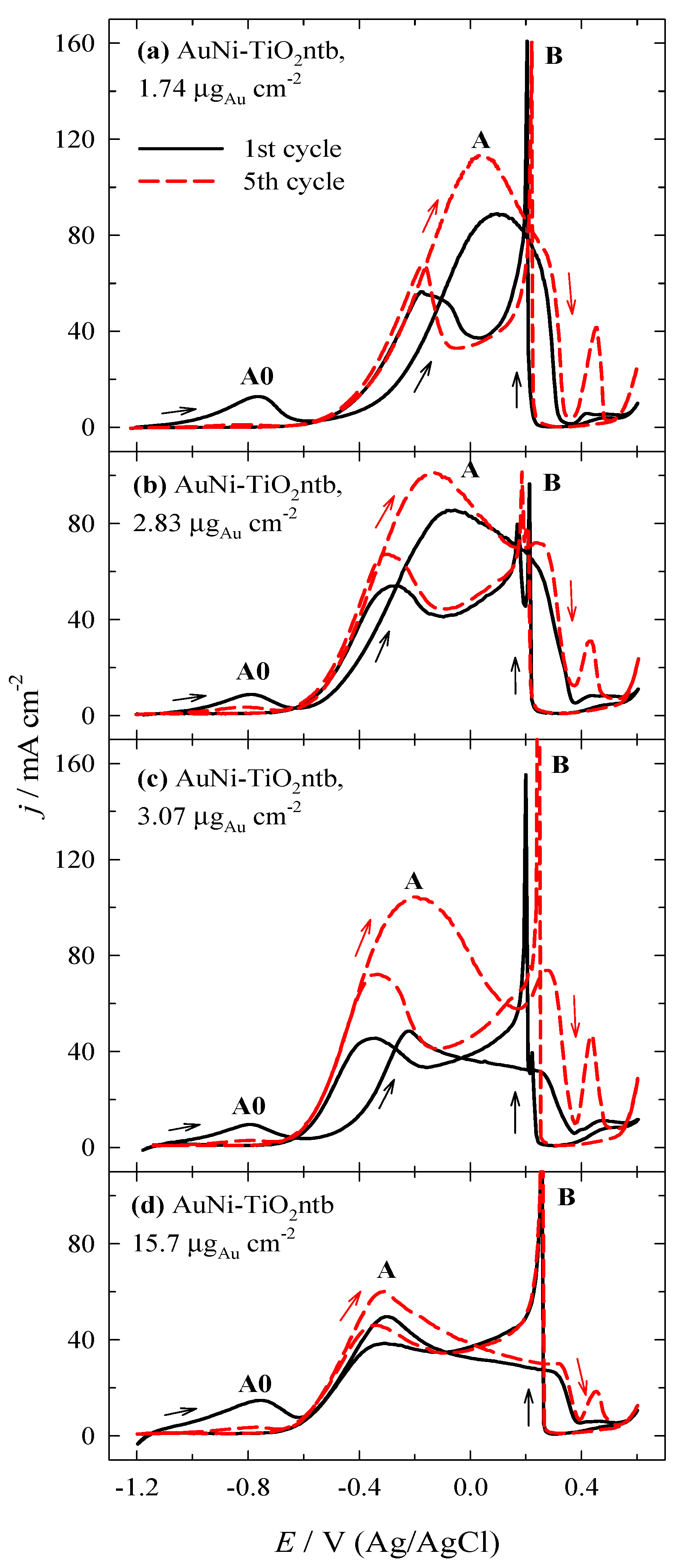
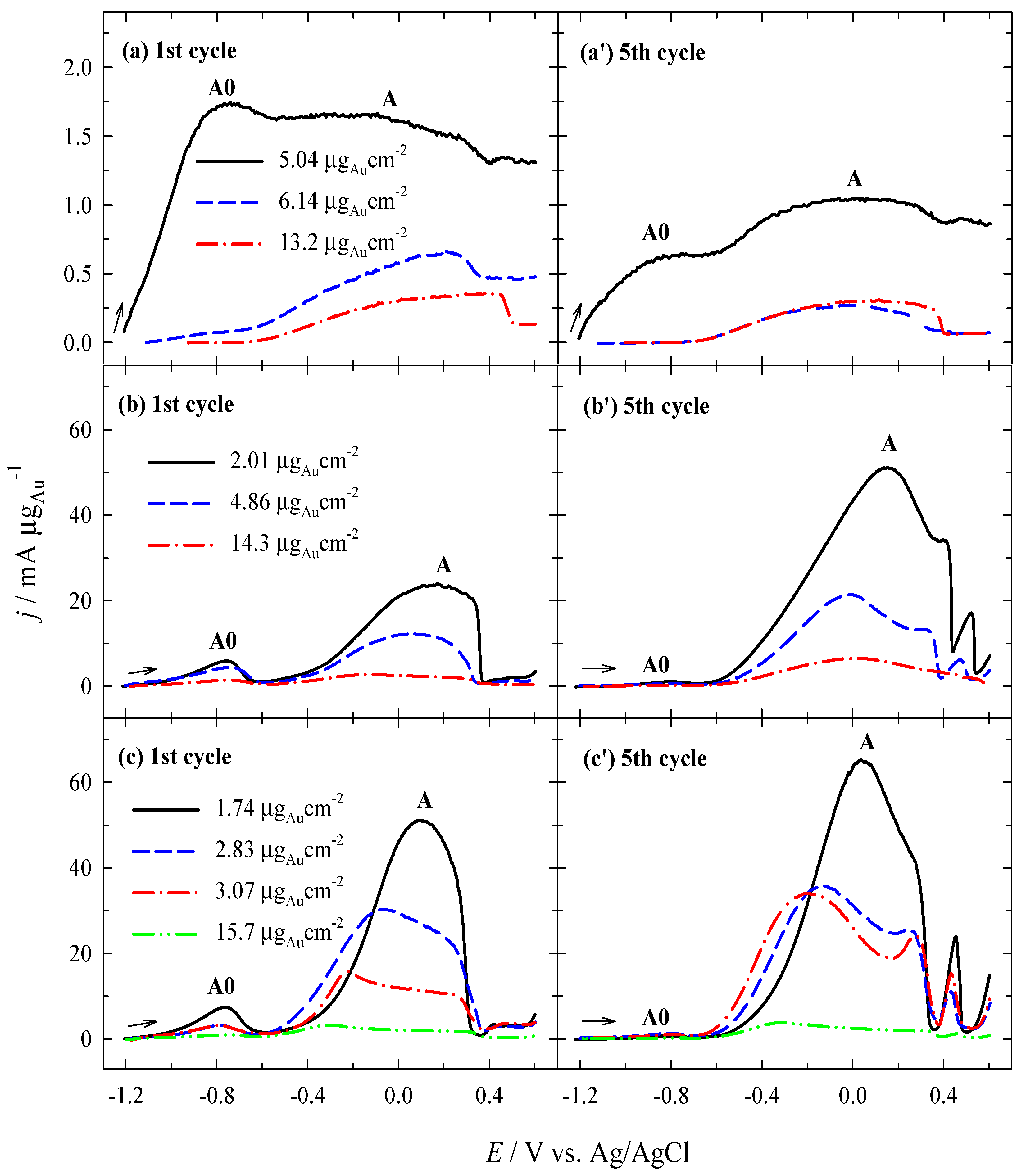
3.2. Investigation of the Oxidation of BH4− Ions
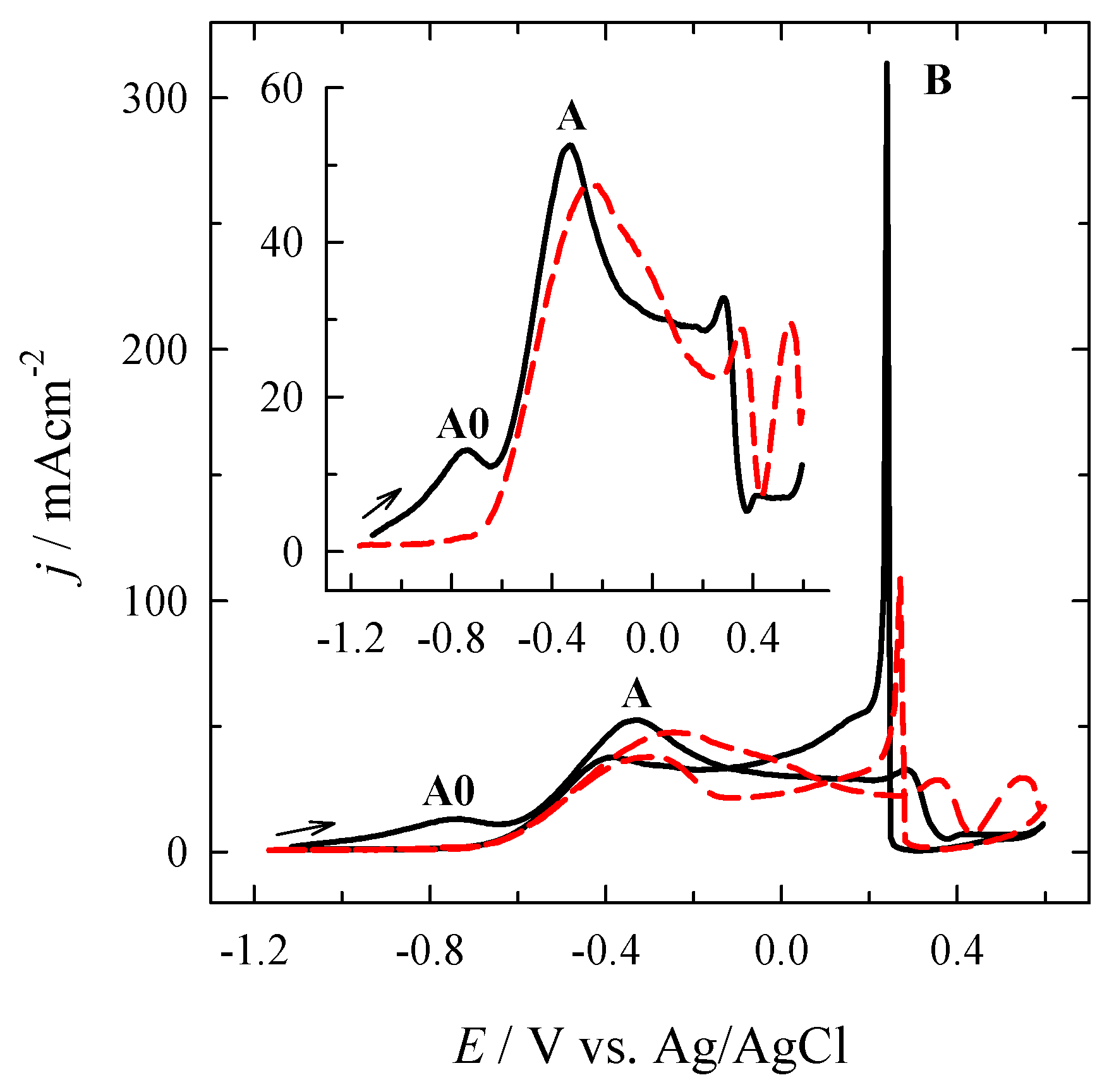
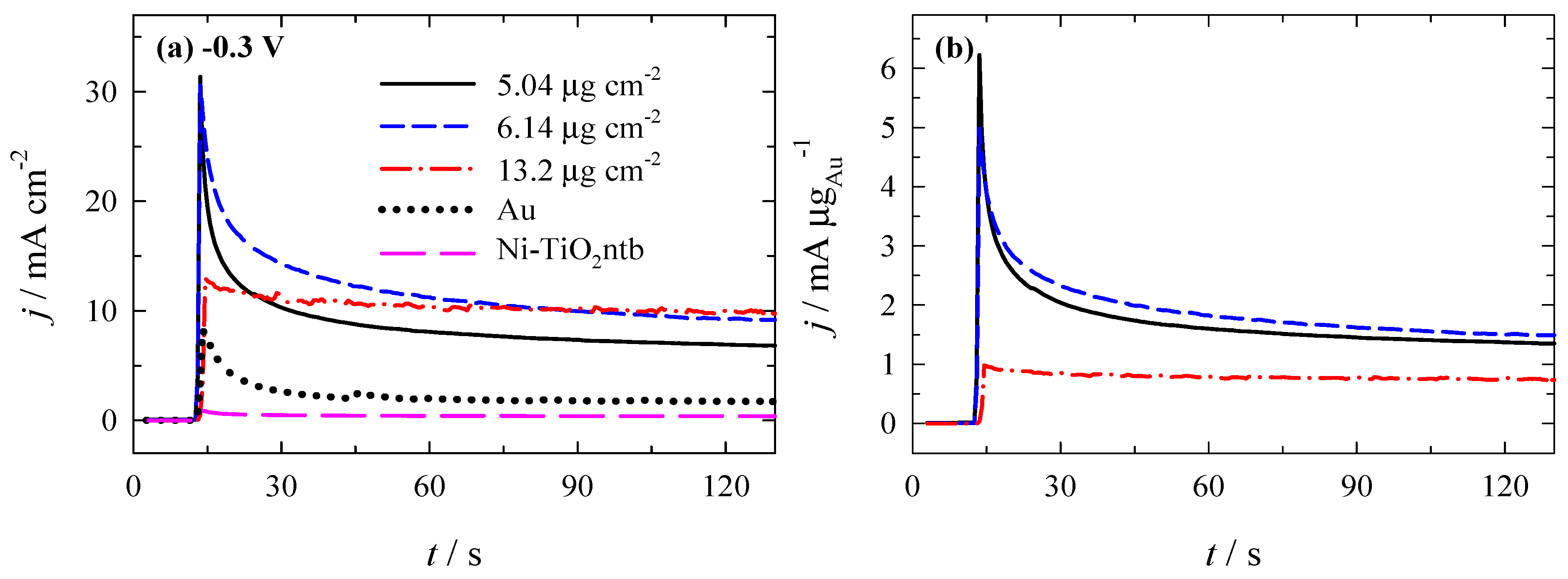
3.3. Stability of Catalysts
3.4. Fuel Cell Test
4. Conclusions
Author Contributions
Funding
Institutional Review Board Statement
Informed Consent Statement
Data Availability Statement
Acknowledgments
Conflicts of Interest
References
- Oshchepkov, A.; Bonnefont, A.; Maranzana, G.; Savinova, E.R.; Chatenet, M. Direct borohydride fuel cells: A selected review of their reaction mechanisms, electrocatalysts, and influence of operating parameters on their performance. Curr. Opin. Electrochem. 2022, 32, 100883–100895. [Google Scholar] [CrossRef]
- Hu, B.; Xu, C.; Chen, P.; Yu, J.; Hu, B.; Xiang, Q.; Cen, Y.; Liu, Y.; Yu, D.; Chen, C. Efficient nickel catalyst with preferred orientation and microsphere for direct borohydride fuel cell. Int. J. Hydrog. Energy 2021, 46, 27516–27528. [Google Scholar] [CrossRef]
- Oh, T.H. Effect of cathode conditions on performance of direct borohydride–hydrogen peroxide fuel cell system for space exploration. Renew. Energy 2021, 178, 1156–1164. [Google Scholar] [CrossRef]
- Yin, X.; Wang, Q.; Duan, D.; Liu, S.; Wang, Y. Amorphous NiB alloy decorated by Cu as the anode catalyst for a direct borohydride fuel cell. Int. J. Hydrog. Energy 2019, 44, 10971–10981. [Google Scholar] [CrossRef]
- Olu, P.-Y.; Job, N.; Chatenet, M. Evaluation of anode (electro) catalytic materials for the direct borohydride fuel cell: Methods and benchmarks. J. Power Sources 2016, 327, 235–257. [Google Scholar] [CrossRef]
- Celik, C.; Boyaci, S.F.G.; Sarac, H.I. Influences of sodium borohydride concentration on direct borohydride fuel cell performance. J. Power Sources 2010, 195, 2599–2603. [Google Scholar] [CrossRef]
- Santos, D.M.F.; Sequeira, C.A.C. Sodium borohydride as a fuel for the future. Renew. Sustain. Energ. Rev. 2011, 15, 3980–4001. [Google Scholar] [CrossRef]
- Kadioglu, T.; Turkmen, A.C.; Ata, K.C.; Akay, R.G.; Tikiz, I.; Celik, C. Investigation of the performance of a direct borohydride fuel cell with low Pt/C catalyst loading under different operating conditions. Int. J. Hydrog. Energy 2020, 45, 35006–35012. [Google Scholar] [CrossRef]
- Olu, P.Y.; Bonnefont, A.; Braesch, G.; Martin, V.; Savinova, E.R.; Chatenet, M. Influence of the concentration of borohydride towards hydrogen production and escape for borohydride oxidation reaction on Pt and Au electrodes—Experimental and modelling insights. J. Power Sources 2018, 375, 300–309. [Google Scholar] [CrossRef]
- Braesch, G.; Bonnefont, A.; Martin, V.; Savinova, E.R.; Chatenet, M. Borohydride oxidation reaction mechanisms and poisoning effects on Au, Pt and Pd bulk electrodes: From model (low) to direct borohydride fuel cell operating (high) concentrations. Electrochim. Acta 2018, 273, 483–494. [Google Scholar] [CrossRef]
- Backović, G.; Milikić, J.; De Negri, S.; Saccone, A.; Šljukić, B.; Santos, D.M.F. Enhanced borohydride oxidation kinetics at gold-rare earth alloys. J. Alloys Compd. 2021, 857, 158273–158282. [Google Scholar] [CrossRef]
- Sukackienė, Z.; Balčiūnaitė, A.; Tamašauskaitė-Tamašiūnaitė, L.; Pakštas, V.; Selskis, A.; Norkus, E. Development of new nanostructured Au/Co/Cu and Au/CoB/Cu catalysts and studies of their catalytic activity. J. Electrochem. Soc. 2015, 162, 734–745. [Google Scholar] [CrossRef]
- Sukackienė, Z.; Balčiūnaitė, A.; Tamašauskaitė-Tamašiūnaitė, L.; Selskis, A.; Jasulaitienė, V.; Norkus, E. Investigation of sodium borohydride oxidation on CoB/Cu and CoBW/Cu modified with Au nanoparticles. Chemija 2015, 26, 141–147. [Google Scholar]
- Jusys, Z.; Behm, R.J. Borohydride electrooxidation over Pt/C, AuPt/C and Au/C catalysts: Partial reaction pathways and mixed potential formation. Electrochem. Commun. 2015, 60, 9–12. [Google Scholar] [CrossRef]
- Olu, P.-Y.; Bonnefont, A.; Chatenet, M. Borohydride oxidation reaction (BOR) at Pt and Au electrodes: From experimental insights to mechanism and kinetic modeling. Encycl. Interfac. Chem. 2018, 384–392. [Google Scholar] [CrossRef]
- Iotov, P.I.; Kalcheva, S.V.; Kanazirski, I.A. On the enhanced electrocatalytic performance of PtAu alloys in borohydride oxidation. Electrochim. Acta 2013, 108, 540–546. [Google Scholar] [CrossRef]
- Amendola, S.C.; Onnerud, P.; Kelly, M.T.; Petillo, P.J.; Sharp-Goldman, S.L.; Binder, M. A novel high power density borohydride-air cell. J. Power Sources 1999, 84, 130–133. [Google Scholar] [CrossRef]
- Chatenet, M.; Micoud, F.; Roche, I.; Chainet, E. Kinetics of sodium borohydride direct oxidation and oxygen reduction in sodium hydroxide electrolyte. Part I. BH4− electrooxidation on Au and Ag catalysts. Electrochim. Acta 2006, 51, 5459–5467. [Google Scholar] [CrossRef]
- Ojani, R.; Valiollahi, R.; Raoof, J.-B. Au hollow nanospheres on graphene support as catalyst for sodium borohydride electrooxidation. Appl. Surf. Sci. 2014, 311, 245–251. [Google Scholar] [CrossRef]
- Atwan, M.H.; Macdonald, C.L.B.; Northwood, D.O.; Gyenge, E.L. Colloidal Au and Au-alloy catalysts for direct borohydride fuel cells: Electrocatalysis and fuel cell performance. J. Power Sources 2006, 158, 36–44. [Google Scholar] [CrossRef]
- Martins, M.; Sljuki, B.; Metin, O.; Sevim, M.; Sequeira, C.A.C.; Sener, T.; Santos, D.M.F. Bimetallic PdM (M = Fe, Ag, Au) alloy nanoparticles assembled on reduced graphene oxide as catalysts for direct borohydride fuel cells. J. Alloys Compd. 2017, 718, 204–214. [Google Scholar] [CrossRef]
- Wang, B.; Wang, G.; Cao, D.; Ye, K.; Cheng, K.; Zhu, K.; Liu, Y.; Zhang, D. A flexible and highly effective paper based gold electrode for sodium borohydride electrocatalysis. Int. J. Hydrog. Energy 2017, 42, 22814–22820. [Google Scholar] [CrossRef]
- Song, C.; Li, B.; Cheng, K.; Ye, K.; Zhu, K.; Cao, D.; Wang, G. Synthesis and investigation of a high-activity catalyst: Au nanoparticles modified metalic Ti microrods for NaBH4 electrooxidation. Int. J. Hydrog. Energy 2018, 43, 3688–3696. [Google Scholar] [CrossRef]
- Caglar, A.; Cogenli, M.S.; Yurtcan, A.B.; Kivrak, H. Effective carbon nanotube supported metal (M = Au, Ag, Co, Mn, Ni, V, Zn) core Pd shell bimetallic anode catalysts for formic acid fuel cells. Renew. Energy 2020, 150, 78–90. [Google Scholar] [CrossRef]
- Castanheira, L.; Dubau, L.; Mermoux, M.; Berthomé, G.; Caqué, N.; Rossinot, E.; Chatenet, M.; Maillard, F. Carbon corrosion inproton-exchange membrane fuel cells: From model experiments to real-life operation in membrane electrode assemblies. ACS Catal. 2014, 4, 2258–2267. [Google Scholar] [CrossRef]
- Zhao, R.; Chen, Y.; Huang, S. Doping engineering on carbons as electrocatalysts for oxygen reduction reaction. Fundam. Res. 2021, 1, 807–823. [Google Scholar] [CrossRef]
- Quílez-Bermejo, J.; Morallón, E.; Cazorla-Amorós, D. Metal-free heteroatom-doped carbon-based catalysts for ORR: A critical assessment about the role of heteroatoms. Carbon 2020, 165, 434–454. [Google Scholar] [CrossRef]
- Xu, H.; Yang, J.; Ge, R.; Zhang, J.; Li, Y.; Zhu, M.; Dai, L.; Li, S.; Li, W. Carbon-based bifunctional electrocatalysts for oxygen reduction and oxygen evolution reactions: Optimization strategies and mechanistic analysis. J. Energy Chem. 2022, 71, 234–265. [Google Scholar] [CrossRef]
- Shao, M.; Chang, Q.; Dodelet, J.-P.; Chenitz, R. Recent advances in electrocatalysts for oxygen reduction reaction. Chem. Rev. 2016, 116, 3594–3657. [Google Scholar] [CrossRef] [Green Version]
- Goktas, S.; Goktas, A. A comparative study on recent progress in efficient ZnO based nanocomposite and heterojunction photocatalysts: A review. J. Alloys Compd. 2021, 863, 158734. [Google Scholar] [CrossRef]
- Mikailzade, F.; Türkan, H.; Önal, F.; Zarbali, M.; Göktaş, A.; Tumbul, A. Structural and magnetic properties of polycrystalline Zn1−xMnxO films synthesized on glass and p-type Si substrates using sol–gel technique. Appl. Phys. A 2021, 127, 408. [Google Scholar] [CrossRef]
- Santos, F.D.M.; Sequeira, C.A.C. Zinc anode for direct borohydride fuel cells. J. Electrochem. Soc. 2010, 157, B13–B19. [Google Scholar] [CrossRef]
- Tamašauskaitė-Tamašiūnaitė, L.; Lichušina, S.; Balčiūnaitė, A.; Zabielaitė, A.; Šimkūnaitė, D.; Vaičiūnienė, J.; Stalnionienė, I.; Žielienė, A.; Selskis, A.; Norkus, E. Zinc-cobalt alloy deposited on the titanium surface as electrocatalysts for borohydride oxidation. J. Electrochem. Soc. 2015, 162, F348–F353. [Google Scholar] [CrossRef]
- Hu, B.; Chen, P.; Xu, C.; Meng, J.; Cai, J.; Yang, Y.; Zhang, B.; Yu, D.; Zhou, X.; Chen, C. Hierarchical leaf-shaped Ni@Zn bimetallic catalyst with high stability and selectivity for borohydride oxidation. Appl. Catal. B Environ. 2022, 307, 121183. [Google Scholar] [CrossRef]
- Dou, M.; Hou, M.; Liang, D.; Lu, W.; Shao, Z.; Yi, B. SnO2 nanocluster supported Pt catalyst with high stability for proton exchange membrane fuel cells. Electrochim. Acta 2013, 92, 468–473. [Google Scholar] [CrossRef]
- Šljukić, B.; Martins, M.; Kayhan, E.; Balčiūnaitė, A.; Şener, T.; Sequeira, C.A.C.; Santos, D.M.F. SnO2-C supported PdNi nanoparticles for oxygen reduction and borohydride oxidation. J. Electroanal. Chem. 2017, 797, 23–30. [Google Scholar] [CrossRef]
- Ma, J.; Li, J.; Yang, S.; Lu, H.; Liu, L.; Wang, R. Ultrathin veil-like SnO2 supported Co3O4 nanoparticles for direct borohydride fuel cell anode. J. Power Sources 2020, 453, 227866. [Google Scholar] [CrossRef]
- Sandoval, A.; Zanella, R.; Klimova, T.E. Titania nanotubes decorated with anatase nanocrystals as support for active and stable gold catalysts for CO oxidation. Catal. Today 2017, 282, 140–150. [Google Scholar] [CrossRef]
- Shi, Z.; Tan, Q.; Wu, D. Enhanced CO2 hydrogenation to methanol over TiO2 nanotubes-supported CuO-ZnO-CeO2 catalyst. Appl. Catal. A Gen. 2019, 581, 58–66. [Google Scholar] [CrossRef]
- Zhuang, C.; Song, Z.; Yu, Z.; Zhang, C.; Wang, J.; Liu, Y.; Zhao, Q. Photoelectrochemical performance of TiO2 nanotube arrays modified with Ni2P Co-catalyst. Int. J. Hydrog. Energy 2021, 46, 4981–4991. [Google Scholar] [CrossRef]
- Chaturvedi, A.; Kundu, P.P. Synthesis of Co-Fe nanoparticle supported on titanium oxide-nanotubes (TiO2-NTs) as enhanced oxygen reduction reaction electrocatalyst. Mater. Today Proceed. 2021, 45, 5518–5522. [Google Scholar] [CrossRef]
- Mao, H.; Zhang, F.; Du, M.; Dai, L.; Qian, Y.; Pang, H. Review on synthesis of porous TiO2-based catalysts for energy conversion systems. Ceram. Int. 2021, 47, 25177–25200. [Google Scholar] [CrossRef]
- Abdullah, M.; Kamarudin, S.K. Titanium dioxide nanotubes (TNT) in energy and environmental applications: An overview. Renew. Sustain. Energy Rev. 2016, 76, 212–225. [Google Scholar] [CrossRef]
- Kim, J.-H.; Ishihara, A.; Mitsushima, S.; Kamiya, N.; Ota, K.-I. Catalytic activity of titanium oxide for oxygen reduction reaction as a non-platinum catalyst for PEFC. Electrochim. Acta 2007, 52, 2492–2497. [Google Scholar] [CrossRef]
- Lincho, J.; Gomes, J.; Kobylanski, M.; Bajorowicz, B.; Zaleska-Medynska, A.; Martins, R.C. TiO2 nanotube catalysts for parabens mixture degradation by photocatalysis and ozone-based technologies. Process. Saf. Environ. Prot. 2021, 152, 601–613. [Google Scholar] [CrossRef]
- Gomes, J.; Lincho, J.; Mazierski, P.; Miodyńska, M.; Zaleska-Medynska, A.; Martins, R.C. Unexpected effect of ozone on the paraben’s mixture degradation using TiO2 supported nanotubes. Sci. Total Environ. 2020, 743, 140831–140844. [Google Scholar] [CrossRef]
- Mazierski, P.; Nischk, M.; Gołkowska, M.; Lisowski, W.; Gazda, M.; Winiarski, J.M.; Klimczuk, T.; Zaleska-Medynska, A. Photocatalytic activity of nitrogen doped TiO2 nanotubes prepared by anodic oxidation: The effect of applied voltage, anodization time and amount of nitrogen dopant. Appl. Catal. B Environ. 2016, 196, 77–88. [Google Scholar] [CrossRef]
- Kowalski, D.; Kim, D.; Schmuki, P. TiO2 nanotubes, nanochannels and mesosponge: Self-organized formation and applications. Nano Today 2013, 8, 235–264. [Google Scholar] [CrossRef]
- Nischk, M.; Mazierski, P.; Gazda, M.; Zaleska, A. Ordered TiO2 nanotubes: The effect of preparation parameters on the photocatalytic activity in air purification process. Appl. Catal. B Environ. 2014, 144, 674–685. [Google Scholar] [CrossRef]
- Noha, K.-J.; Namb, I.; Hana, J.W. Nb-TiO2 nanotubes as catalyst supports with high activity and durability for oxygen reduction. Appl. Surf. Sci. 2020, 521, 146330–146337. [Google Scholar] [CrossRef]
- Zhu, S.; Wang, Q.; Cao, D.; Zhao, S.; Xu, W.; Li, C.; Wang, Y. CdTe and Ag nanoparticles co-modified TiO2 nanotube arrays for the enhanced wastewater treatment and hydrogen production. J. Environ. Chem. Eng. 2022, 10, 107207–107219. [Google Scholar] [CrossRef]
- Hsieh, B.-J.; Tsai, M.-C.; Pan, C.-J.; Su, W.-N.; Rick, J.; Chou, H.-L.; Lee, J.-F.; Hwang, B.-J. Tuning metal support interactions enhances the activity and durability of TiO2-supported Pt nanocatalysts. Electrochim. Acta 2017, 224, 452–459. [Google Scholar] [CrossRef]
- Mathloom, A.A.L.; Abed, A.A. Titanium dioxide thin film prepared by sol-gel technique. J. Educ. Pure Sci. Univ. Thi-Qar 2019, 9, 241–258. [Google Scholar]
- Xu, Y.; Ahmed, R.; Lin, Q.; Zangari, G. (Photo) electrochemical water oxidation at anodic TiO2 nanotubes modified by electrodeposited NiFe oxy-hydroxides catalysts. Electrochim. Acta 2019, 308, 91–98. [Google Scholar] [CrossRef]
- Puga, M.L.; Venturini, J.; Caten, C.S.; Bergman, C.P. Influencing parameters in the electrochemical anodization of TiO2 nanotubes: Systematic review and meta-analysis. Ceram. Int. 2022, 48, 19513–19526. [Google Scholar] [CrossRef]
- Roy, P.; Berger, S.; Schmuki, P. TiO2 nanotubes: Synthesis and applications. Angew. Chem. Int. Ed. 2011, 50, 2904. [Google Scholar] [CrossRef]
- Ponche-de-Leon, C.; Bavykin, D.V.; Walsh, F.C. The oxidation of borohydride ion at titanate nanotube supported gold electrodes. Electrochem. Commun. 2006, 8, 1655–1660. [Google Scholar] [CrossRef]
- Tamašauskaitė-Tamašiūnaitė, L.; Balčiūnaitė, A.; Šimkūnaitė, D.; Selskis, A. Self-ordered titania nanotubes and flat surfaces as a support for the deposition of nanostructured Au-Ni catalyst: Enhanced electrocatalytic oxidation of borohydride. J. Power Sources 2012, 202, 85–91. [Google Scholar] [CrossRef]
- Balčiūnaitė, A.; Tamašauskaitė-Tamašiūnaitė, L.; Santos, D.M.F.; Zabielaitė, A.; Jagminienė, A.; Stankevičienė, I.; Norkus, E. Au nanoparticles modified Co/titania nanotubes as electrocatalysts for borohydride oxidation. Fuel Cells 2017, 17, 690–697. [Google Scholar] [CrossRef]
- Gouda, M.H.; Gouveia, W.; Elessawy, N.A.; Šljukić, B.; Nassr, A.B.A.A.; Santos, D.M.F. Simple design of PVA-based blend doped with SO4 (PO4)-functionalised TiO2 as an effective membrane for direct borohydride fuel cells. Int. J. Hydrog. Energy 2020, 45, 15226–15238. [Google Scholar] [CrossRef]
- Volochanskyi, O.; Svecov, M.; Bartůněk, V.; Prokopec, V. Electroless deposition via galvanic displacement as a simple way for the preparation of silver, gold, and copper SERS-active substrates. Colloids Surf. A Physicochem. Eng. Asp. 2021, 616, 126310–126317. [Google Scholar] [CrossRef]
- Milazzo, R.G.; Privitera, S.M.S.; Scalese, S.; Mirabella, S.; Bongiorno, C.; Lombardo, S.A.; Rimini, E. New insight into Pt nucleation mechanism on Si surface during galvanic displacement deposition. J. Phys. Chem. Solids 2021, 148, 109722–109730. [Google Scholar] [CrossRef]
- Bian, W.; Liu, Z.; Lian, G.; Wang, L.; Wang, Q.; Zhan, J. High reliable and robust ultrathin-layer gold coating porous silver substrate via galvanic-free deposition for solid phase microextraction coupled with surface enhanced Raman spectroscopy. Anal. Chim. Acta 2017, 994, 56–64. [Google Scholar] [CrossRef] [PubMed]
- Jung, J.Y.; Kim, D.G.; Jang, I.; Kim, N.D.; Yoo, J.S.; Kim, P. Synthesis of hollow structured PtNi/Pt core/shell and Pt-only nanoparticles via galvanic displacement and selective etching for efficient oxygen reduction reaction. J. Ind. Eng. Chem. 2022, 111, 300–307. [Google Scholar] [CrossRef]
- Chen, C.S.; Wu, C.-H.; Fan, T.-L.; Hsieh, Y.-C.; Tso, K.-C.; Lee, J.-F.; Wu, P.-W. Pt deposition on Ni-based superalloy via a combination of galvanic displacement reaction and chemical reduction. Mater. Chem. Phys. 2020, 254, 123475–123482. [Google Scholar] [CrossRef]
- Tian, T.; Xiao, X.; Liu, R.; She, H.; Hu, X. Study on titania nanotubes arrays prepared by titanium anodization in NH4F/H2SO4 solution. J. Mater. Sci. 2007, 42, 5539–5543. [Google Scholar] [CrossRef]
- Wagner, C.D.; Riggs, W.M.; Davis, L.E.; Moulder, J.E. Handbook of X-ray Photoelectron Spectroscopy; Perkin—Elmer Corporation: Waltham, MA, USA, 1978; p. 190. [Google Scholar]
- Available online: http://srdata.nist.gov/xps (accessed on 20 April 2022).
- Luna, A.L.; Novoseltceva, E.; Louarn, E.; Beaunier, P.; Kowalska, E.; Ohtani, B.; Valenzuela, M.A.; Remita, H.; Colbeau-Justin, C. Synergetic effect of Ni and Au nanoparticles synthesized on titania particles for efficient photocatalytic hydrogen production. Appl. Catal. B Environ. 2016, 191, 18–28. [Google Scholar] [CrossRef] [Green Version]
- He, Q.; Wan, Y.; Jiang, H.; Pan, Z.; Wu, C.; Wang, M.; Wu, X.; Ye, B.; Ajayan, P.M.; Song, L. Nickel vacancies boost reconstruction in nickel hydroxide electrocatalyst. ACS Energy Lett. 2018, 3, 1373–1380. [Google Scholar] [CrossRef]
- Gao, M.Y.; Sun, C.B.; Lei, H.; Zeng, J.R.; Zhang, Q.B. Nitrate-induced and in situ electrochemical activation synthesis of oxygen deficiencies-rich nickel/nickel (oxy)hydroxide hybrid films for enhanced electrocatalytic water splitting. Nanoscale 2018, 10, 17546–17551. [Google Scholar] [CrossRef]
- Chen, X.; Li, P.; Jin, Z.; Meng, Y.; Yuan, H.; Xiao, D. Tri-metallic phytate in situ electrodeposited on 3D Ni foam as a highly efficient electrocatalyst for enhanced overall water splitting. J. Mater. Chem. A 2017, 5, 18786–18792. [Google Scholar] [CrossRef]
- Peng, W.-C.; Chen, Y.-C.; He, J.-L.; Ou, S.-L.; Horng, R.-H.; Wuu, D.-S. Tunability of p- and n-channel TiOx thin film transistors. Sci. Rep. 2018, 8, 9255. [Google Scholar] [CrossRef] [PubMed] [Green Version]


| Plating Solution | M | pH | T, °C | Time, s |
|---|---|---|---|---|
| Electroless Ni plating | ||||
| NiSO4 NH2CH2COOH NaH2PO2 CH2(COONa)2 | 0.10 0.40 0.25 0.10 | 9 | 85 | 5 20 60 |
| Deposition of Au crystallites | ||||
| HAuCl4 | 0.001 | 1.8 | 25 | 10–1800 |
| No. | Catalyst Fabrication Conditions | Element, at.% | Atomic Ratio of Au:Ni | Au Loading, μgAu·cm−2 | |||||
|---|---|---|---|---|---|---|---|---|---|
| X, s | Y, s | Au | Ni | P | O | Ti | |||
| 1 | 5 | 60 | 0.25 | 0.9 | 0.23 | 50.02 | 48.59 | 1:3.6 | 5.04 |
| 2 | 5 | 300 | 0.41 | 0.22 | 0.15 | 53.31 | 45.91 | 1.8:1 | 6.11 |
| 3 | 5 | 1800 | 0.74 | - | 0.03 | 44.99 | 54.27 | 1:0 | 13.20 |
| 4 | 20 | 10 | 0.09 | 31.56 | 4.49 | 24.91 | 38.94 | 1:350 | 2.01 |
| 5 | 20 | 20 | 0.39 | 31.62 | 4.65 | 32.08 | 31.27 | 1:81 | 4.86 |
| 6 | 20 | 60 | 0.79 | 22.58 | 4.08 | 29.73 | 42.81 | 1:28 | 14.30 |
| 7 | 60 | 10 | 0.10 | 61.85 | 7.50 | 4.00 | 26.55 | 1:618 | 1.74 |
| 8 | 60 | 20 | 0.15 | 61.25 | 7.27 | 4.60 | 26.73 | 1:408 | 2.83 |
| 9 | 60 | 60 | 0.76 | 65.53 | 9.44 | 4.77 | 19.53 | 1:86 | 3.07 |
| 10 | 60 | 300 | 1.68 | 55.75 | 8.13 | 4.57 | 29.87 | 1:33 | 15.70 |
| Catalyst | Thickness, nm | Element | |||||||
|---|---|---|---|---|---|---|---|---|---|
| Ni2p3/2 | P2p | O1s | Ti2p3/2 | ||||||
| at.% | Eb, eV | at.% | Eb, eV | at.% | Eb, eV | at.% | Eb, eV | ||
| (a) | 0 | 9.7 8.78 | 852.4 855.7 | 1.69 1.32 | 129.5 162.8 | 78.51 | 531.5 | - | - |
| 4 | 77.94 | 852.4 | 2.64 | 129.4 | 1.4 18.02 | 529.3 531.1 | - | - | |
| 44 | 85.22 | 852.4 | 1.77 | 129.2 | 11.74 | 530.5 | 1.28 | 458.3 | |
| (b) | 0 | 14.19 9.26 | 852.4 855.6 | 4.33 | 129.5 | 72.21 | 531.5 | - | - |
| 4 | 86.27 | 852.4 | 5.47 | 129.5 | 0.59 7.67 | 533.3 531.1 | - | - | |
| 44 | 91.32 | 852.4 | 3.18 | 129.4 | 5.15 | 531.4 | 0.35 | 458.8 | |
| Catalyst | Thickness, nm | Element | |||||||||
|---|---|---|---|---|---|---|---|---|---|---|---|
| Au4f7/2 | Ni2p3/2 | P2p | O1s | Ti2p3/2 | |||||||
| at.% | Eb, eV | at.% | Eb, eV | at.% | Eb, eV | at.% | Eb, eV | at.% | Eb, eV | ||
| (a) | 0 | 19.11 | 83.6 | 12.88 1.70 | 855.5 852.3 | 1.50 | 132.6 | 62.72 | 531.0 | 2.09 | 459.2 |
| 4 | 27.82 | 83.6 | 63.81 | 852.3 | 2.86 | 129.4 | 4.66 0.86 | 530.7 532.1 | - | - | |
| 44 | 0.31 | 83.6 | 89.92 | 852.4 | 2.54 | 128.8 | 5.96 | 530.9 | 0.78 0.50 | 453.8 459.5 | |
| 344 | - | - | 25.47 | 852.4 | 1.10 | 129.2 | 27.14 19.30 | 530.2 531.0 | 16.26 10.91 | 458.6 455.3 | |
| (b) | 0 | 27.79 | 83.5 | 1.25 9.90 | 855.2 852.4 | - | - | 10.86 50.20 | 532.6 530.8 | - | - |
| 4 | 12.31 | 83.5 | 79.19 | 852.4 | 8.05 | 129.3 | 0.06 0.39 | 531.0 530.7 | - | - | |
| 44 | 0.22 | 83.6 | 92.72 | 852.4 | 3.29 | 129.5 | 1.32 2.03 | 530.4 531.7 | 0.43 | 458.3 | |
| (c) | 0 | 15.09 | 83.5 | 14.41 | 855.5 | - | - | 70.51 | 531.3 | - | - |
| 4 | 72.12 | 83.6 | 25.10 | 852.4 | - | - | 1.37 | 531.4 | 0.40 | 454.7 | |
| 44 | 0.87 | 83.6 | 92.75 | 852.4 | 2.62 | 129.3 | 0.36 2.87 | 530.0 531.4 | 0.07 0.45 | 453.4 460.1 | |
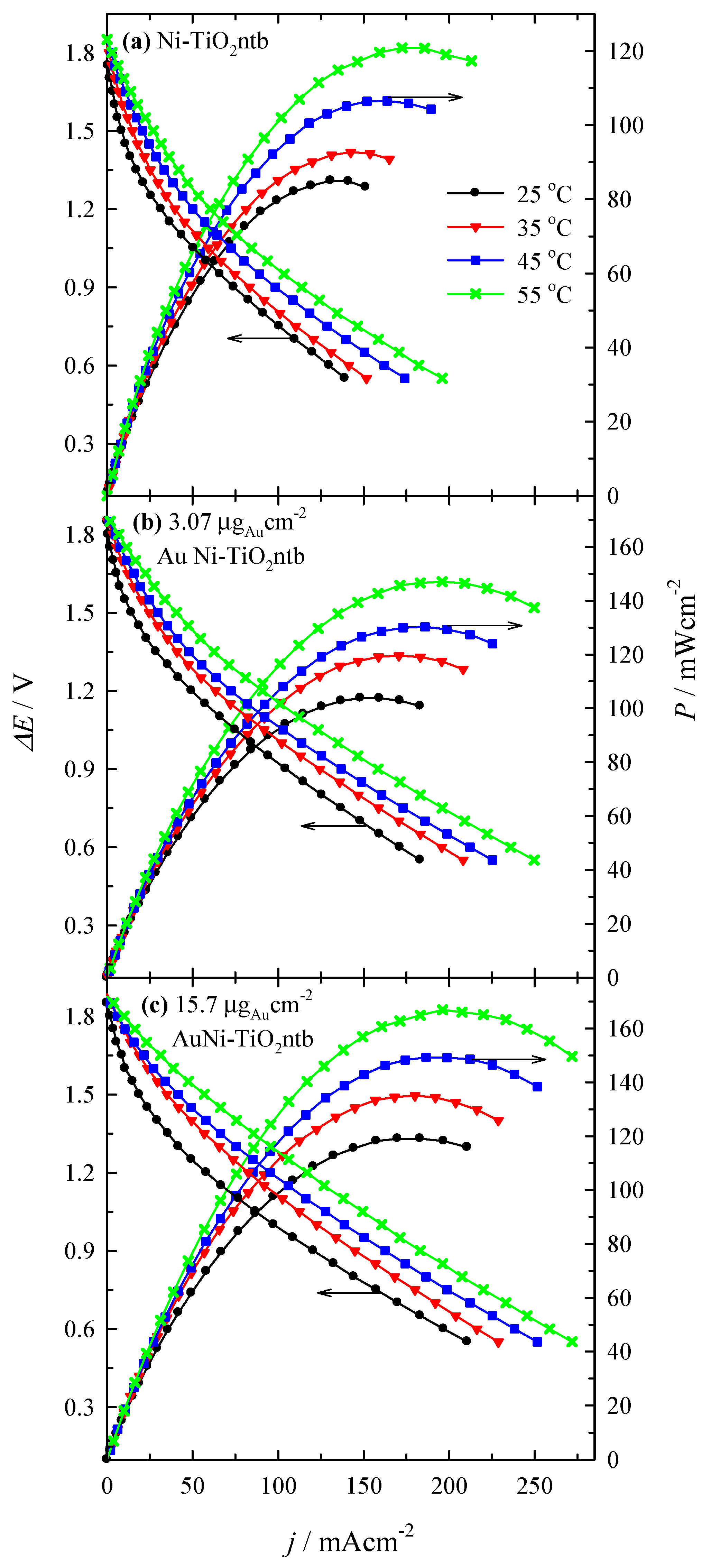
| Catalyst | Au Loading (µgAu·cm−2) | T (°C) | Peak Power Density (mW·cm−2) | j at Peak Power Density (mA·cm−2) | E at Peak Power Density (V) | Specific Peak Power Density (mW·µgAu−1) |
|---|---|---|---|---|---|---|
| Ni-TiO2ntb | - | 25 | 85.0 | 130.6 | 0.65 | - |
| 35 | 92.7 | 142.5 | 0.65 | - | ||
| 45 | 106.5 | 163.7 | 0.65 | - | ||
| 55 | 120.8 | 172.5 | 0.70 | - | ||
| AuNi-TiO2ntb | 3.07 | 25 | 103.8 | 148.1 | 0.70 | 33.8 |
| 35 | 119.5 | 170.6 | 0.70 | 38.9 | ||
| 45 | 130.2 | 185.9 | 0.70 | 42.4 | ||
| 55 | 147.0 | 195.9 | 0.75 | 47.9 | ||
| 15.7 | 25 | 119.1 | 183.1 | 0.65 | 7.6 | |
| 35 | 135.1 | 180.0 | 0.75 | 8.6 | ||
| 45 | 149.3 | 186.5 | 0.80 | 9.5 | ||
| 55 | 166.9 | 196.2 | 0.85 | 10.6 |
Publisher’s Note: MDPI stays neutral with regard to jurisdictional claims in published maps and institutional affiliations. |
© 2022 by the authors. Licensee MDPI, Basel, Switzerland. This article is an open access article distributed under the terms and conditions of the Creative Commons Attribution (CC BY) license (https://creativecommons.org/licenses/by/4.0/).
Share and Cite
Balčiūnaitė, A.; Zabielaitė, A.; Sukackienė, Z.; Kepenienė, V.; Šimkūnaitė, D.; Selskis, A.; Tamašauskaitė-Tamašiūnaitė, L.; Norkus, E. Fabrication of Efficient Gold−Nickel-Supported Titania Nanotube Electrocatalysts for Sodium Borohydride−Hydrogen Peroxide Fuel Cells. Coatings 2022, 12, 850. https://doi.org/10.3390/coatings12060850
Balčiūnaitė A, Zabielaitė A, Sukackienė Z, Kepenienė V, Šimkūnaitė D, Selskis A, Tamašauskaitė-Tamašiūnaitė L, Norkus E. Fabrication of Efficient Gold−Nickel-Supported Titania Nanotube Electrocatalysts for Sodium Borohydride−Hydrogen Peroxide Fuel Cells. Coatings. 2022; 12(6):850. https://doi.org/10.3390/coatings12060850
Chicago/Turabian StyleBalčiūnaitė, Aldona, Aušrinė Zabielaitė, Zita Sukackienė, Virginija Kepenienė, Dijana Šimkūnaitė, Algirdas Selskis, Loreta Tamašauskaitė-Tamašiūnaitė, and Eugenijus Norkus. 2022. "Fabrication of Efficient Gold−Nickel-Supported Titania Nanotube Electrocatalysts for Sodium Borohydride−Hydrogen Peroxide Fuel Cells" Coatings 12, no. 6: 850. https://doi.org/10.3390/coatings12060850
APA StyleBalčiūnaitė, A., Zabielaitė, A., Sukackienė, Z., Kepenienė, V., Šimkūnaitė, D., Selskis, A., Tamašauskaitė-Tamašiūnaitė, L., & Norkus, E. (2022). Fabrication of Efficient Gold−Nickel-Supported Titania Nanotube Electrocatalysts for Sodium Borohydride−Hydrogen Peroxide Fuel Cells. Coatings, 12(6), 850. https://doi.org/10.3390/coatings12060850