Abstract
Barium titanate coatings were, for the first time, sprayed by a high feed-rate plasma torch with water stabilization of the plasma. Two power levels of the torch were applied for spraying to cover steel substrates. Various substrate preheating levels from 125 °C to 377 °C were used to modify cooling conditions. Microstructure and phase composition including crystallinity quantification were observed. Dielectric measurements proved that the relative permittivity between 300 and 400 coatings is too temperature sensitive over 170 °C but fits the requirements of the EIA temperature coefficient between room temperature and 170 °C. Simultaneously, the loss tangent remains rather low, between 0.02 and 0.07, in a broad range of temperatures and frequencies. Annealing was performed in air to heal the oxygen deficiency, but only modified the microstructure insignificantly. The dielectric properties of as-sprayed and annealed samples were discussed, with the main finding that the temperature coefficient of permittivity was improved by annealing. This study contributes to the search for the suitability of plasma-sprayed BaTiO3 coatings for application in the electrical industry, namely by the optimization of conditions for high feed-rate spraying.
1. Introduction
Barium titanate BaTiO3 is the longest existing ferroelectric perovskite material, a ceramic with a series of structural phase transitions [1]. Due to its high relative permittivity and low dielectric loss tangent, barium titanate is most typically used in capacitors, but frequently also in other energy-storage devices. Coatings with thicknesses between 10 μm and 1 mm are considered thick films [2,3]. The properties of these layered structures are usually considered to be comparable with bulk materials, but various aspects of the rapid solidification of thermally sprayed thick films influence their microstructure and properties. Among them, porosity, stress, multi-modal grain size distribution, and phase mismatch are often responsible for the less-stable dielectric behavior compared to bulk.
One of the most important production techniques for thick ceramic films is plasma spraying [4]. A value of relative permittivity of about 2500 was reported for plasma-sprayed barium titanate, but the loss tangent of these samples was high, at about 0.45 [5]. Sometimes, the sprayed coatings were markedly darker than the starting powder [6]. The dark blue color of the strongly reduced BaTiO3 [7,8] is typically attributed to a small-polaron hopping of electrons of Ti3+–Ti4+ charge transfer type and provides evidence of the strongly disordered nature of the material [9]. The net dipole moment of BaTiO3 bulk has a value of 26 µC/cm2 [10].
The method of accomplishing thermal spray is as follows: (i) Melt the feedstock powder material, (ii) accelerate the melt during the flight, and (iii) impact on a substrate where rapid solidification occurs and deposit build-up takes place. The high process temperature is achieved in an electric arc, which ionizes the gas or water representing the plasma-forming medium. In the case of the WSP system used here, water is the medium. The dissociated and ionized water vapor forms a plasma jet and provides acceleration to the molten particles towards the target substrate, where the material solidifies, forming a deposit. The deposit is built up by successive impingement of individual flattened particles called „splats“. The sequence of successive passes of the plasma jet over the substrate, i.e., repeated spray trajectory, is carried out by a robotic arm or other multiaxial manipulators.
The earlier results of our team [11] showed that the plasma-sprayed BaTiO3 coating has a significantly broader temperature range of stability of the pseudo-tetragonal phase than bulk BaTiO3 materials. This phase remained stable between at least −30 °C and +175 °C, and its presence resulted in relative permittivity values between 400 and 1600 (the exact value was dependent on the processing route), without any sharp changes, which could be expected around the transformation temperatures. The pseudo-tetragonal phase, existing at room temperature, was however identified as cubic by XRD, because of its very small tetragonality. This raised the question of whether the plasma spraying of BaTiO3 might not be a promising technology for the preparation of lead-free ferroelectric ceramics with a broader-than-usual stability range.
Additional heat treatment was reported as a promising method for healing macroscopic defects [7,12], the crystallization of amorphous fraction [7,12], and also for oxygen stoichiometry restoration [8]. However, studies of the annealing effect on the microstructure modification and the dielectric properties of plasma-sprayed BaTiO3 are missing.
For quantification of the temperature stability of permittivity, a coefficient is established according to prescriptions of the US Electronic Industries Alliance (EIA), called TCC. In the case of linear dielectrics, we can expect a monotonous increase in the permittivity with increasing temperatures [13], and only two temperatures are satisfactory for the calculation of TCC. In non-linear materials, such as BaTiO3, particularly considering the shifted transformation range [11], we cannot preclude when the largest departure from the room-temperature permittivity is expected. Therefore, the plausible approach is to display TCC over the entire studied range in graphical form [14,15,16] and compare it with the EIA classification limits. As a relevant case for barium titanate, X5R to X9R classes were shown [17], but the studied samples were shown in problems to exhibit the permittivity drift lower than the desirable ±15%, especially in the high-temperature window from 200 to 250 °C.
The role of barium titanate coatings operates purely in dielectric applications. Regarding serving as protective coatings, there exist plenty of better ceramic materials, e.g., zirconia for thermal barriers, chromia for anti-wear applications, and alumina for simple electrical insulation. That is why mechanical or strength characteristics were out of the scope of the actual report.
The goal of this paper is to show how the substrate temperature influences the dielectric parameters of the as-sprayed BaTiO3, and how the dielectric parameters and their stability are further modified by annealing. A high-feed-rate, water-stabilized spray torch (WSP) [18] was used for spraying, but the general contours of this study also are transferable to more common plasma systems.
2. Materials and Methods
2.1. Sample Preparation
Barium titanate powder of a non-commercial origin [8], with a particle size in the range of 63–125 µm, was deposited by the WSP spraying technique [8,13,19]. The plasma torch current was set to 500 A and electric power to 150 kW, which are the maximum available parameters. Next, spray runs were performed at 400 A, and therefore at the reduced electric power of 130 kW. Compressed air was used as the powder-feeding gas in all cases. The feed rate was fixed at about 12 kg per hour. Substrates made of structural steel S235 with the dimensions 125 × 25 × 3 mm3 were preheated directly by the plasma torch pass just before spraying. Temperatures between 125 °C and 377 °C were adjusted to enhance adhesion, using a different temperature for each coating, with the purpose to obtain samples with more accelerated cooling and slower cooling. The uniformity of preheating was monitored by pyrometers, and the robot trajectory was programmed in a pattern providing the optimal uniformity of the temperature over the substrate size. The sprayed coatings were finally approximately 1.5 mm thick. For dielectric measurements, the original surface roughness must be removed, and plan-parallel faces prepared. During this step, the thickness of coatings was reduced to about 0.9 mm by grinding. The system of coating labeling is summarized in Table 1. The annealing regime was selected as a necessary minimum to reach full crystallization conditions without influencing the microstructure [8,19]. The annealing was performed in a laboratory furnace working with an ambient air atmosphere. A temperature of 700 °C was maintained for 4 h, whereas heating and cooling ramps were set to 7 °C/min.

Table 1.
Coating labeling system.
2.2. Characterization
Polished cross-sections of the coatings were prepared for microscopic observation. All coating cross-sections were subjected to a standardized materialographic procedure including precision cutting (Secotom 50, Struers, Ballerup, Denmark) followed by grinding and polishing (Tegramin 25, Struers, Ballerup, Denmark). Scanning electron microscopy (SEM) observation was performed with Phenom-Pro microscope (Thermo Fisher Sci., Bleiswijk, the Netherlands) equipped with a CeB6 thermionic cathode and working in the backscattered electron (BSE) mode. The images were collected at 10 kV electron beam tension.
The phase composition and lattice parameters were detected by means of X-ray diffraction (XRD), using the D8 Discover powder diffractometer (Bruker, Bremen, Germany) in a Bragg–Brentano geometry with a 1D detector and Cu-Kα radiation (scanned region from 20 to 130° 2θ with step size 0.03° 2θ and 192 s counting time per step). The size of coherently diffracting domains (CDD) and microstrains was evaluated by a quantitative Rietveld analysis from the broadening of diffraction peaks using TOPAS V5 software (Bruker AXS, Karlsruhe, Germany). It was assumed that small crystallites and microstrains contribute to the broadening of Lorentzian and Gaussian components of the pseudo-Voigt function, respectively [20].
Electrical measurements of both as-sprayed and annealed samples were performed on coatings adhering to the metallic substrate that served as the bottom electrode. Layers of aluminum as thin-film electrodes were sputtered under reduced pressure on the topside of each sample. To measure the dielectric parameters of the samples, a three-electrode setup was used, where the electric field was applied parallel to the spraying direction (i.e., perpendicular to the substrate surface). Capacitance was measured in a frequency range from 100 Hz to 1 MHz and a temperature range from 30 °C to 250 °C (step 10 °C) with a programmable impedance analyzer (4284A, Agilent, Santa Clara, CA, USA) [7]. The applied voltage was 1V AC and samples were placed using the fixture BDS-1200 in a heated cell Novotherm (Novocontrol, Montabaur, Germany). The relative permittivity εr was calculated from the measured capacitances CP and specimen dimensions. Relative permittivity εr is directly proportional to CP according to Equation (1).
where ε0 = 8.854 × 10⁻¹² F m−1; S/k [m] is the ratio between the guarded surface S and the thickness of the sample k. The same arrangement and equipment were used for the loss tangent measurement at the same frequencies as capacitance.
CP = ε0 × εr × S/k
Since we were not equipped with a device enabling precise dielectric measurements in under-zero Celsius temperatures, we decided to shift the stability study range up. The interval width is 255 °C for X9R and 205 °C for the X8R category [17]. In our case, this width was 220 °C, ranging from +30 to +250 °C, with the frequency fixed to 1 kHz. The upper end of this range between 200 and 250 °C is typically not reported but could be important for monitoring phenomena critical for the vanishing of acceptable stability of dielectric behavior.
Electric resistance was measured with a special resistivity adapter, Keithley, model 6105. The electric field was applied with the help of a regulated high-voltage source and the values recorded by a multi-purpose electrometer (617C, Keithley Instruments, Solon, OH, USA). The testing signal voltage was 100 ± 0.05 V DC, and the time of exposure was 10 min. Volume resistivity was calculated from the measured resistance values and specimen dimensions.
3. Results and Discussion
3.1. Microstructure and Phase Composition
Figure 1 shows the microstructures of the as-sprayed coatings, A2 and B6, before and after annealing. Simply stated, there is no substantial difference between these coatings, representing extremes among the spray parameters. Based on this, we can suggest that all coatings exhibit very similar microstructures. The microstructure is always characterized by defects such as pores, microcracks, and imperfect alignment of the neighboring lamellas. Before and after annealing, the main features appear non-affected.
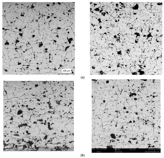
Figure 1.
(a) SEM-BSE micrograph of polished cross-section of as-sprayed samples “A2” left and “B6” right; (b) SEM-BSE micrographs of polished cross-section of annealed samples “A2ann” left and “B6ann” right. Scale is the same for all micrographs.
All coatings contained a tetragonal BaTiO3 phase (#00-05-0626) according to XRD. The X-ray diffraction patterns are displayed in Figure 2. Sample A2 is fully crystalline but sample B6 has an amorphous halo between 25° 2θ and 30° 2θ. For high-power, as well as low-power, conditions, the result is similar, where the high-preheat coatings are completely crystalline, and the low-preheat coating is not. High-preheat coatings represent slower cooling and more time for crystallization. The BaCO3 phase (#00-044-1487) is a product of decomposition in plasma—the products of which are the same as residuum from the powder production route, i.e., thermal decomposition of barium acetate.
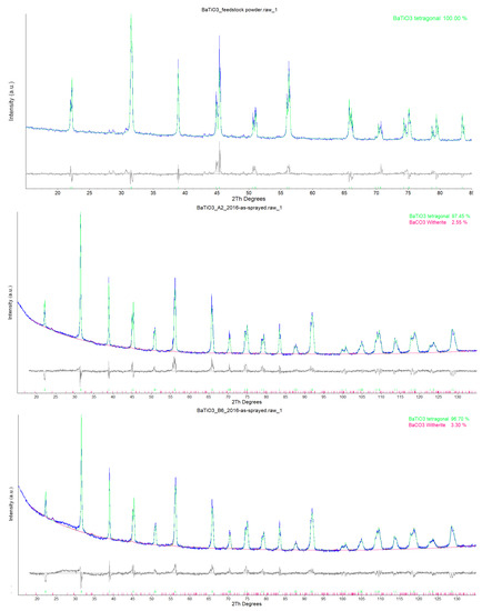
Figure 2.
XRD patterns of the (from the top) feedstock powder; sample A2; sample B6. The Rwp curve indicating the precision of the fit is shown in grey under each XRD pattern.
3.2. Dielectric Properties
Low-preheat as-sprayed sample A6 has a more pronounced frequency decrease in permittivity compared to high-preheat sample A2, as shown in Figure 3. The maximum permittivity is higher for A6, i.e., 450, compared to A2 with a value of 380. The loss tangent of A2 is, however, lower (below 0.02). In both cases, the high-temperature and low-frequency corner of the 3D graph shows a peak in the loss tangent. Similar is the low-power sample, B2, with an even slightly higher permittivity maximum—at a value of 480. All these samples had the same Curie temperature (i.e., position of the permittivity peak) at 130 °C. This peak is not as pronounced as usual for bulk BaTiO3, but it clearly exists. In the case of the annealed sample, A2ann, this peak is absent, and the frequency and temperature characteristics of the permittivity are flat. This is an attribute of so-called linear dielectric materials instead of the usually non-linear BaTiO3, but here the loss tangent tends to rise at a high frequency.
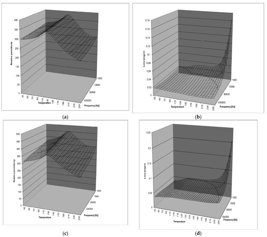
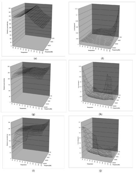
Figure 3.
Dielectric parameters of the as-sprayed and annealed BaTiO3 coatings. Sample A2 (a) relative permittivity, (b) loss tangent; sample A6 (c) relative permittivity, (d) loss tangent; sample B2 (e) relative permittivity, (f) loss tangent; annealed sample A2ann (g) relative permittivity, (h) loss tangent; annealed sample A6ann (i) relative permittivity, (j) loss tangent.
At the same time, the “central” values of the loss tangent (i.e., between 75 °C and 200 °C and also between 10 kHz and 100 kHz) remain the same as before annealing, at about 0.02 to 0.03.
The trend among samples A1–A6–B2 is increasing permittivity at similar losses. After annealing, at a high frequency and low temperature (i.e., the opposite corner of the f-T plane of the 3D graph), the decreased permittivity and increased loss tangent are dramatically more pronounced for the low-preheat coating A6ann than the high-preheat coating A2ann. Theoretically, low substrate preheating favors suppression of crystallization via a high cooling rate. Such a partly amorphous sample would need very intensive annealing for crystallization. Our mild, only electron-behavior-affecting annealing is not high enough, and the resulting sample exhibits an insufficiently strong change in the microstructure: Crack networks, pores, and poor interlamellar locking were already present, c.f. Figure 1.
The surface of coating A6 was darker than all other samples [19]. The substrate preheated to a lower temperature induced a certain amorphous content in the coating, as shown in Table 2. This amorphous fraction was responsible for higher permittivity. At the same time, the partly amorphous coatings contained slightly finer crystallites, as shown in Table 2. The grain boundaries block the polarization and charge transfer, but very weakly, and the influence of the amorphous phase is predominant. Since the amorphous matter is characterized by defects such as dangling bonds, the defects and surface are occupied with the absorbed hydroxyl groups and water molecules. They all could be easily driven by the electric field. The higher relative permittivity at the low frequency could be attributed to increased polarizability associated with these features.
Table 2.
XRD results.
When the grain size of ceramics increases, for example with an increasing dopant concentration, the proportion of the grain boundary declines. The defects, such as vacancies and voids, change the distribution of positive and negative charges at the interface. However, as a result of the grain boundary area decrease, these defects are reduced [15]. The decrease in the ceramic relative permittivity could be attributed to that phenomenon. Another method of vacancies and/or voids removal is thermal posttreatment.
Annealing as low as 500 °C was shown to be high enough to make the frequency characteristic (10–105 Hz range) of the BaTiO3 single crystal substantially flatter [21]. This very mild, only-vacancies-affecting (and therefore electron-behavior-affecting) annealing is enough in the case of a single crystal to modify its dielectric response. Very small values of our measured loss tangent are similar to BaTiO3 thin films [22], sintered at a temperature of 900 °C or lower. Thin films are not as susceptible to the accumulation of defects as thick films. The non-changing relative permittivity in specific frequency and temperature ranges, as well as the low dielectric loss tangent, are very important for the application of BaTiO3 films in electronic devices.
The controlling mechanism of the permittivity dispersion in BaTiO3 is an anodic-type process where the migrating species are H+ protons injected from the adsorbed water film. This results in the reduction of Ti4+ to Ti3+ ions. The stoichiometries of the Ti-rich phases require a valence change in Ti (e.g., Ba2Ti6O13) to accommodate the oxygen deficiencies while maintaining electroneutrality [23].
The variable relative permittivity values between 400 and 1600 [11] in the case of plasma-sprayed BaTiO3 can be considered acceptable in a non-textured polycrystalline material. The relative permittivity values in the order of 1600 were obtained for polycrystalline BaTiO3, assuming the relative permittivity along the c-axis of the crystal lattice of 225 and along the a-axis of 4400, for a single crystal [24]. The cation vacancies are created by cationic migration to the surface of each grain. These vacancies represent acceptor states, which may trap electrons from energy levels above the trap state. The number of electrons available for conduction would be drastically reduced by this means, and the resistivity of the oxygen-depletion layer would likely increase by several orders of magnitude. Does such a layer also exist in plasma-sprayed coatings?
The resistivities are summarized in Figure 4. Although the resistivities vary, we can observe systematically decreased resistivity for the annealed samples within the corresponding series. The difference between the two as-sprayed samples is always lower than the deviation of the annealed sample. We can gain insight into the reproducibility of results measured on a single sample by comparing two identical as-sprayed samples in each series, A2, A3, etc. The second visible trend is the systematically lower resistance for the B samples, i.e., low-power sprayed coatings. The influence of preheating is not clear—the high-preheat samples, A2 and B2, are more resistive than the low-preheat samples, but these trends are not followed by all series.
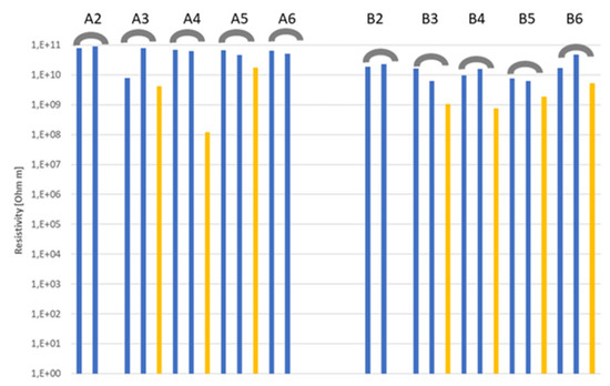
Figure 4.
Electric resistivity [Ωm]. The blue columns are for as-sprayed and yellow columns for annealed samples. In series A2, A6, and B2, the annealed sample was not tested.
Comparing the TCC values in Figure 5 and Figure 6, we see that a strong majority of coatings meets the limit ±15% between 30 °C and 170 °C. Higher temperatures induce destabilization of the dielectric response, similarly as in the case of variously doped bulks [14,15,16]. Concerning the Curie temperature at about 130 °C, there is always the local maximum of TCC, but in the case of annealed coatings, it is much less pronounced.
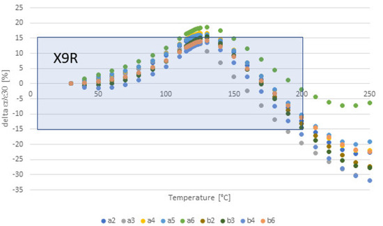
Figure 5.
TCC of all as-sprayed samples at 1 kHz frequency; X9R class is represented by the frame.
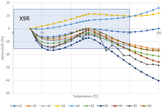
Figure 6.
TCC of all annealed coatings at 1 kHz frequency, X9R class is represented by the frame.
Figure 7 and Figure 8 show the temperature dependence of the loss tangent. For the annealed coating, the “central” values (i.e., between 75 °C and 200 °C) are lower, between 0.01 and 0.02. This is a lower loss tangent than the limit emphasized by EIA, which is 0.05. However, the annealed coatings have higher losses at low temperatures.
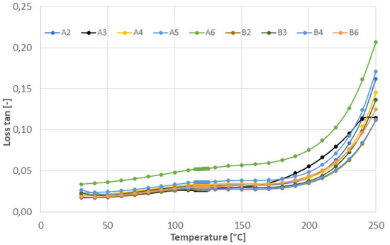
Figure 7.
Loss tangent of all as-sprayed coatings at 1 kHz frequency.
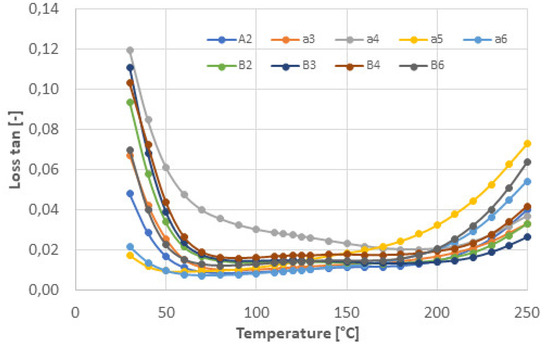
Figure 8.
Loss tangent of all annealed coatings at 1 kHz frequency.
Here, with BaTiO3, we see that the annealed coatings are slightly worse dielectrics than the as-sprayed ones. Similar permittivity, a less stable loss tangent, the absence of the Currie peak, decreased resistivity, and more dispersed TCC are the addressed aspects. The clue lies in the phase. The amorphous proportion, indicated in A6 and B6 coatings, crystallized at 700 °C, preferably to TiO2 rutile. This may result from the fact that the sub-micrometric structure of the amorphous material is of lower symmetry and lower density than bulk BaTiO3, making it more structurally similar to thin films made from the amorphous precursor [25]. The pioneer work of Javadpour and Eror [26] reported that at crystallization from an amorphous compound with Ti excess, the BaTi4O9 phase forms as the preferential component at heating to only 600 °C with 4 h dwell. However, as a similar compound, BaTi5O11 is prone to rapidly decomposing to TiO2 and BaTi4O9. We suppose that partial crystallinity of the as-sprayed coating led to the crystallization of the amorphous residuum to TiO2 and BaTiO3. Here the Ti-rich phases require a valence change in Ti to accommodate the oxygen deficiencies while maintaining electroneutrality [23].
However, at high frequencies, the loss tangent is not perfectly stable for the annealed coatings and starts to increase, similarly to the work of Schneller et al. [27]. There was a large increase in the loss tangent at higher frequencies, which may have been due to finite resistance at the electrode [28], while the frequency-independent losses predominate at low and intermediate frequencies. The permittivity and loss tangent of such a thin film at a frequency of 100 kHz were 600 and 0.045, respectively [28]. The low dispersion of the relative permittivity and the absence of any relaxation peak on the loss tangent curve indicate that interfacial polarization of the Maxwell–Wagner type was produced by the electrode barrier [28]. Between room temperature and 170 °C, there is no markedly changed loss tangent in the case of our as-sprayed coatings, similar to in the work of Tripathi et al. [29]. Moreover, between 100 Hz and 10 kHz, our samples exhibit a decreasing loss tangent alongside the frequency [29].
Figure 9 shows SEM-BE micrographs of the polished cross-section of coating A2. The arrows show structural features that are candidates for space-charge polarization layers. They represent either individual splats (lamellas) or layers present at intersplat boundaries, showing different shades. However, the element mapping showed absolutely homogeneous distributions with any anomalies associated with these layers. In this way, a purely chemical explanation cannot be applied, and only certain local differences between Ti4+ and Ti3+ ions should be associated with the origin of such layers. The presence of lamellar features (splats) in the plasma-sprayed coatings inherently means that when we tested the coating in the spray direction (and this is obvious since this is the capacitor area and the perpendicular direction is the capacitor thickness), the charge moves through and/or versus many boundaries. In other words, the structure is significantly anisotropic. Splats with their dimensions—about 60 µm in diameter and 4 µm in thickness—are like very flat grains separated by (sometimes non-detectably thin) grain boundaries. The denser the microstructure, the higher the influence of these boundaries at the expense of the influence of voids.
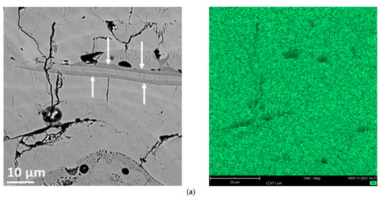
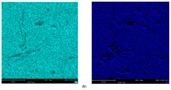
Figure 9.
(a) SEM-BSE micrographs of polished cross-section of as-sprayed samples “A2” and map of Ba element, (b) map of Ti element (left) and O element (right).
Figure 10 shows the resistivity dependence on the bias DC voltage for the coatings of the series A. All coatings exhibit the ohmic behavior typical for the n-type BaTiO3 [30], whereas only sample A6 deviates from the trend, showing p-type behavior [30] with resistivity decreasing from 60 to 300 V for less than half the order of magnitude. This is the only sample significantly reduced in plasma [19] and also the only one sprayed on the substrate that remained under the detected “transition temperature” 130 °C, cf. Table 1. It means that in order for the vacancies to predominate over the void and boundary effects in the coating, they need a very cold substrate and a high cooling rate associated with this low temperature.
Figure 10.
Resistivity dependence on the bias DC voltage.
4. Conclusions
Barium titanate coatings were successfully plasma sprayed by a high feed-rate torch with water as a medium for plasma stabilization. Relative permittivity between 300 and 400 was lower than the common bulk values due to defects typical for plasma-sprayed coatings. The loss tangent between 0.02 and 0.07 and volume resistivity in the order of 1010 Ωm are, however, characteristics seldom reached by as-sprayed barium titanate coatings. The stability study of such a broad range had not been published for thermally sprayed BaTiO3. Dielectric measurements proved that the relative permittivity of the coatings is too temperature sensitive over 170 °C but fits the requirements of the EIA-established temperature coefficient TCC between room temperature and 170 °C. Simultaneously, the loss tangent remains rather low in a broad range of temperatures and frequencies.
The influence of annealing on dielectric properties is rather problematic—the attributes of the Currie point disappear, while the loss tangent as well as the TCC are more dispersed than for the as-sprayed coatings. However, the dielectric properties did not strongly deteriorate with annealing.
To summarize, plasma-sprayed (WSP) barium titanate is a non-ferroelectric material, but a rather high-permittivity dielectric with reasonably flat frequency and temperature characteristics, which is also not very microstructurally sensitive to in-service heating up to 700 °C. Considering that large areas of variously shaped metals could be easily covered with this material via high feed-rate WSP spraying, BaTiO3 coatings become much more interesting.
Author Contributions
Conceptualization, P.C.; methodology, P.C.; writing—original draft preparation, P.C.; writing—review and editing, P.C; XRD analysis and interpretation, F.L.; SEM analyses were arranged externally as a barter service; dielectric measurements, L.S. and J.S. All authors have read and agreed to the published version of the manuscript.
Funding
This research received no external funding.
Institutional Review Board Statement
Not applicable.
Informed Consent Statement
Not applicable.
Data Availability Statement
Not applicable.
Acknowledgments
The author would like to thank Petr Veselý, SEM operator.
Conflicts of Interest
The author declares no conflict of interest.
References
- Jaffe, B.; Cook, W.R.; Jaffe, H. Piezoelectric Ceramics; Academic Press: New York, NY, USA, 1971. [Google Scholar]
- Solanki, A.; Shrivastava, J.; Upadhyay, S.; Choudhary, S. Modified Structural, Morphological and Photo Electrochemical Properties of 120 MeV Ag9+ Ion Irradiated BaTiO3 Thin Films. Curr. Appl. Phys. 2013, 13, 344–350. [Google Scholar] [CrossRef]
- Stojanovic, B.D.; Foschini, C.R.; Pavlovic, V.B.; Pavlovic, V.M. Barium Titanate Screen-printed Thick Films. Ceram. Int. 2002, 28, 293–298. [Google Scholar] [CrossRef]
- Sampath, S. Thermal Spray Applications in Electronics and Sensors: Past, Present, and Future. J. Therm. Spray Technol. 2010, 19, 921–949. [Google Scholar] [CrossRef]
- Zhiguo, X.; Haidou, W.; Lina, Z.; Xinyuan, Z.; Yanfei, H. Properties of the BaTiO3 Coating Prepared by Supersonic Plasma Spraying. J. Alloys Compd. 2014, 582, 246–252. [Google Scholar]
- Ctibor, P.; Sedlacek, J.; Pala, Z. Structure and Properties of Plasma Sprayed BaTiO3 Coatings after Thermal Posttreatment. Ceram. Int. 2015, 41, 7453–7460. [Google Scholar] [CrossRef]
- Ctibor, P.; Ageorges, H.; Sedlacek, J.; Ctvrtlik, R. Structure and Properties of Plasma Sprayed BaTiO3 Coatings. Ceram. Int. 2010, 36, 2155–2162. [Google Scholar] [CrossRef]
- Ctibor, P.; Čížek, J.; Sedláček, J.; Lukáč, F. Dielectric Properties and Vacancy-like Defects in Plasma Sprayed Barium Titanate. J. Am. Ceram. Soc. 2017, 100, 2972–2983. [Google Scholar] [CrossRef]
- Schrader, M.; Mienert, D.; Oh, T.-S.; Yoo, H.-I.; Becker, K.D. An Optical, EPR and Electrical Conductivity Study of Blue Bariumtitanate, BaTiO3−δ. Solid State Sci. 2008, 10, 768–775. [Google Scholar] [CrossRef]
- Hüfner, S. Photoelectron Spectroscopy; Springer: Berlin, Germany, 1995. [Google Scholar]
- Ctibor, P.; Seiner, H.; Sedláček, J.; Pala, Z.; Vaněk, P. Phase Stabilization in Plasma Sprayed BaTiO3. Ceram. Int. 2013, 39, 5039–5048. [Google Scholar] [CrossRef]
- Pakseresht, A.H.; Rahimipour, M.R.; Vaezi, M.R.; Salehi, M. Effect of Heat Treatment on the Microstructure and Dielectric Property of Plasma Sprayed Barium Titanate Films. Int. J. Mater. Res. 2016, 107, 28–34. [Google Scholar] [CrossRef]
- Ctibor, P.; Sedlacek, J.; Musalek, R.; Tesar, T.; Lukac, F. Structure and Electrical Properties of Yttrium Oxide Sprayed by Plasma Torches from Powders and Suspensions. Ceram. Int. 2021, 48, 7464–7474. [Google Scholar] [CrossRef]
- Wang, M.; Xie, J.; Xue, K.; Li, L. Effects of Zn2+/Mg2+ Ratio on Dielectric Properties of BaTiO3-based Ceramics with Excellent Temperature Stability: Experiments and the First-principle Calculations. Ceram. Int. 2022, 48, 847–854. [Google Scholar] [CrossRef]
- Xie, J.; Li, L.; Wang, M.; Xue, K. Structural Evolution and Dielectric Properties of (Bi, Mg, Zr)-doped BaTiO3 Ceramics for X8R-MLCC Application. Mater. Chem. Phys. 2022, 277, 125263. [Google Scholar] [CrossRef]
- Wang, H.; Cao, M.; Mao, T.; Fu, J.; Pan, W.; Hao, H.; Yao, Z.; Liu, H. Fabrication of BaTiO3@FeO Core-shell Nanoceramics for Dielectric Capacitor Applications. Scr. Mater. 2021, 196, 113753. [Google Scholar] [CrossRef]
- Zhao, N.; Liang, P.; Wu, D.; Chao, X.; Yang, Z. Temperature Stability and Low Dielectric Loss of Lithium-doped CdCu3Ti4O12 Ceramics for X9R Capacitor Applications. Ceram. Int. 2019, 45, 22991–22997. [Google Scholar] [CrossRef]
- Hrabovsky, M. Water-stabilized Plasma Generators. Pure Appl. Chem. 1998, 70, 1157–1162. [Google Scholar] [CrossRef][Green Version]
- Ctibor, P.; Lukáč, F.; Sedláček, J.; Ryukhtin, V. Barium Titanate Dielectrics Sprayed by a High Feed-rate Water-stabilized Plasma Torch. J. Mater. Eng. Perform. 2018, 27, 5291–5299. [Google Scholar] [CrossRef]
- Tagliente, M.A.; Massaro, M. Strain-driven (0 0 2) Preferred Orientation of ZnO Nanoparticles in Ion-implanted Silica. Nuclear Inst. Meth. Phys. Res. Sect. B Beam Interact. Mater. At. 2008, 266, 1055–1061. [Google Scholar] [CrossRef]
- Mohammed, Q.A.; Ali, Z.R.; Mijbas, A.F. Electrical and Optical Properties of Dielectric BaTiO3 Single Crystals Prepared by Flux Technique. J. Babylon Univ. 2012, 1, 79–90. [Google Scholar]
- Bajac, B.; Vukmirovic, J.; Tripkovic, D.; Djurdjic, E.; Stanojev, J.; Cvejic, Z.; Skoric, B.; Srdic, V.V. Structural Characterization and Dielectric Properties of BaTiO3 Thin Films Obtained by Spin Coating. Process. Appl. Ceram. 2014, 8, 219–224. [Google Scholar] [CrossRef]
- Janosik, W.; Randall, C.A.; Lanagan, M. Thermodynamic and Electrical Effects of Residual Carbon in Glass–Barium Titanate Composites for MLCC Applications. J. Am. Ceram. Soc. 2007, 90, 2415–2419. [Google Scholar] [CrossRef]
- Marutake, M. Elastic Constants of Porous Materials, Especially of BaTiO3 Ceramics. J. Phys. Soc. Jpn. 1956, 807, 231–240. [Google Scholar]
- Yoon, S.Y.; Yoon, Y.K.; Yom, S.S. Electrical and Optical Properties of Amorphous BaTiO3 Thin Films Grown by Metalorganic Chemical Vapor Deposition on Indium Thin Oxide-Coated Glass. Jpn. J. Appl. Phys. 1994, 33, 6663–6666. [Google Scholar] [CrossRef]
- Javadpour, J.; Eror, N.G. Raman Spectroscopy of Higher Titanate Phases in the BaTiO3-TiO2 System. J. Am. Ceram. Soc. 1988, 71, 206–213. [Google Scholar] [CrossRef]
- Schneller, T.; Halder, S.; Waser, R.; Pithan, C.; Dornseiffer, J.; Shiratori, Y.; Houben, L.; Vyshnavi, N.; Majumder, S.B. Nanocomposite Thin Films for Miniaturized Multi-layer Ceramic Capacitors Prepared from Barium Titanate Nanoparticle Based Hybrid Solutions. J. Mater. Chem. 2011, 21, 7953–7965. [Google Scholar] [CrossRef]
- Lee, E.J.H.; Pontes, F.M.; Leite, E.R.; Longo, E.; Varela, J.A.; Arajuo, E.B.; Eiras, J.A. Preparation and Properties of Ferroelectric BaTiO3 Thin Films Produced by the Polymeric Precursor Method. J. Mat. Sci. Lett. 2000, 19, 1457–1459. [Google Scholar] [CrossRef]
- Tripathi, A.K.; Chariar, V.; Goel, T.C.; Pillai, P.K.C. Preparation and Characterization of Spray-pyrolysed BaTiO3 Films. Mat. Sci. Eng. 1994, B25, 34–38. [Google Scholar] [CrossRef]
- Kumar, N.; Patterson, E.A.; Fromling, T.; Cann, D.P. DC-bias dependent impedance spectroscopy of BaTiO3–Bi(Zn1/2Ti1/2)O3 ceramics. J. Mater. Chem. C 2016, 9, 1782–1786. [Google Scholar] [CrossRef]
Publisher’s Note: MDPI stays neutral with regard to jurisdictional claims in published maps and institutional affiliations. |
© 2022 by the authors. Licensee MDPI, Basel, Switzerland. This article is an open access article distributed under the terms and conditions of the Creative Commons Attribution (CC BY) license (https://creativecommons.org/licenses/by/4.0/).