Article

Investigation on Sliding Tribological Properties of Laser Cladding Alloy Coating for Subway Wheels

State Key Laboratory of Performance Monitoring and Protecting of Rail Transit Infrastructure, East China Jiaotong University, Nanchang 330013, China
*
Author to whom correspondence should be addressed.
Coatings 2022, 12(10), 1561; https://doi.org/10.3390/coatings12101561
Submission received: 17 September 2022 / Revised: 11 October 2022 / Accepted: 12 October 2022 / Published: 16 October 2022
(This article belongs to the Special Issue Tribological Properties and Wear Protection of Coatings and Alloys)

Abstract

:
The wheel pair is a key component of the subway. Routes of subway conditions are more complex, while frequent starting and braking are more likely to cause wheel damage. To improve the sliding tribological properties of subway wheels, this article focused on laser-cladding technology to repair the wheel. Ni-based and Fe-based alloy coatings were prepared. The microstructure of the coatings was studied by SEM, EDS, XRD, and 3D optical morphology. The mechanical properties of the coating were studied by the Vickers microhardness tester and MFT-EC4000 reciprocating electrochemical friction and wear tester. There are mainly γ(Ni, Fe), Cr7C3, Cr23C6, and other phases in the Ni-based coating, and there are mainly γ-Fe, (Fe, Ni), (Fe-Cr-Ni) solid solution and other phases in the Fe-based coating. The hardness of the Ni-based coating is 250 HV0.7, which is essentially the same as the hardness of the substrate. The hardness of the Fe-based coating reaches a maximum of 715HV0.7. The hardness of the Fe-based coating is 2.86 times higher than the hardness of the substrate. The Fe-based coating is strengthened by the solid solution due to the existence of the solid-solution phase. The Ni-based coating in high-temperature performance is general. Its hardness and friction performance were also ordinary. The results of the study can provide theoretical and technical guidance for the application of laser-cladding technology on subway wheels.

1. Introduction

Rail transportation such as metro and light rail trains has become one of the most important options in China to relieve traffic pressure mainly for cities because of the high transportation capacity and efficiency. According to the data of the China Urban Rail Transit Association, as of June 2022, the mileage of subway operation in China reached 7529.02 km. Although no major and serious safety accidents had occurred so far, the development of the industry and the passage of time have put pressure on safe operation. Wheels are one of the key components of subway vehicles. Compared with high-speed trains, subway lines have more complex conditions, such as frequent starting and braking that can easily cause wheel damage [1]. Common forms of wheel damage include tread wear, tread scuffing, tread peeling, wheel rim wear, wheel rim loss, and wheel out of round [2]. During the service of the wheels, the relative sliding between the wheels and rails can cause abrasion of the wheel treads. Therefore, to ensure the safety of the train, it is necessary to study the wheel sliding friction performance. One promising method is laser cladding, which deposits a surface layer of another material. It has high wear and RCF crack resistance [3]. Laser-cladding technology has significant advantages in enhancing metallic materials, allowing the surface of the substrate to obtain excellent properties [4]. Most scholars believe that laser-cladding technology can select different alloy powder materials for cladding to obtain alloy coatings with properties such as friction reduction, wear resistance, fatigue resistance, corrosion resistance, and oxidation resistance. It has a broad application prospect in the field of repair of high-value-added parts. It is very important to choose suitable alloy powder for laser cladding. At present, Fe-based and Ni-based powders are widely used in wheel and rail materials. The organization, performance, and characteristics of the two powders are different. The Fe-based powder has good wear resistance, but self-fusing compared to other powders is poor. The Fe-based powder is easy to oxide, and oxidation resistance is poor. The Ni-based powder’s advantages are more prominent, with good impact resistance, oxidation resistance, and excellent wear and corrosion resistance. Moreover, self-fusing performance is good, but there are some shortcomings in the high-temperature performance.
The current methods to enhance the matrix properties using laser-cladding technology are: (1) Selecting metal powders with excellent properties for cladding [5]; (2) Quantitatively adding alloying elements with specific functionality to the alloy powder [6]; (3) Adjusting the laser-cladding-process parameters [7,8]. Xu [9] explored the Inconel 625 alloy coating on the surface of 316L stainless steel and studied its metallographic organization as well as mechanical properties. The results showed that all the properties were improved, which proved the importance of the optimal selection of the laser-melting alloy powder. Liu [10] also conducted a similar study and found that using laser-cladding technology to apply a Co-based coating to the locally worn surface of train brake disks resulted in a clad layer with excellent wear resistance, proving that Co-based alloy powder is also a good material for repairing local damage. Jiang [11], on the other hand, prepared a laser-melting coating on the surface of the Ti-6Al-4V substrate and added WC-Co particles by the controlled variable method, the results showing that the addition of WC-Co could improve the wear resistance of the coating, proving that the addition of an appropriate number of alloying elements could enhance the performance of the coating. Most of the studies so far have focused on the same alloy coating and explored whether the addition of different elements can improve the performance or make the structure more stable, and less often have made comparisons from different alloy coatings. Moreover, the relationship between the selective suitability of alloy powders and the enhancement of substrate properties is vital also.
This paper focuses on two alloy powders, the Ni-based and the Fe-based, to analyze the dry sliding friction wear properties of their alloy coatings in the application of subway wheels. Scanning electron microscopy (SEM), energy dispersive spectroscopy (EDS), X-ray diffractometer (XRD), 3D optical three-dimensional morphology, and Vickers microhardness tester were used to analyze the microscopy morphology, phase types, interface elements, and hardness of the alloy coatings.

2. Materials and Methods

The material of the base was ER9 wheel steel (Table 1) and the alloy powder was the Fe-based powder (Table 2) and the Ni-based powder (Table 3).
The equipment used for the laser-cladding test was the Laser line LDF6000-100 laser flexible additive manufacturing system (Figure 1). The parameters of the cladding test are shown in Table 4, and the multi-layer cladding process is shown in Figure 2.
Figure 3 shows the samples of the laser cladding. The samples after the laser cladding were processed into specimens of size 10 mm × 10 mm × 10 mm using an EDM wire cutting machine. A metallographic specimen grinding and polishing machine was used to grind and polish. After that, the samples were cleaned twice with an ultrasonic cleaning apparatus and finally dried using a dryer.
The instrument used for the dry friction test was the MFT-EC4000 reciprocating electrochemical friction and wear tester. Figure 4 shows the diagram of the friction pair in the experiment. The test was carried out under dry friction conditions. The detailed test parameters are shown in Table 5. The load of 10 N was applied for two reasons. Firstly, due to the limitation of the equipment, the maximum load is 20 N. To reduce the error, the load is chosen to be 10 N. Secondly, a load of 10 N, together with a small friction ball diameter, is sufficient to generate large contact stress for the comparative study of frictional wear of different metal materials. The maximum contact stress is calculated according to Equation (1).
σ max = 0.388 PE 2 R 2 3
The counter-sample for the analyzed materials is the Si3N4. Its elastic modulus is 28,420~46,060 MPa. It is a common counter-grinding material because it is an important structural ceramic material with high hardness, lubricity, wear resistance, and oxidation resistance at high temperatures. It was chosen as the counter-sample material because of its high hardness reaching about 2200 HV. Moreover, the Si3N4 was selected as the counter-sample because the real wheel-rail wear could not be achieved, so a high hardness material was used for a short period of time to achieve the experimental purpose. At the same time, the experiments were mainly conducted to analyze the wear performance at the interface and to compare the differences between the two coatings and the substrate.
The microstructure morphology of the coating and the interface were observed with a Hitachi SU8010 field emission scanning electron microscope. The chemical composition, elemental percentage, and distribution in the microstructure were tested with an energy spectrometer. In addition, an X-ray diffractometer was used to analyze the physical composition of the coating with a scanning speed of 4°/min and a scanning range from 10~90°. Vickers hardness tester was used to test the microhardness of the samples. Finally, a 3D optical profilometer was used to analyze the surface morphology and established the 3D morphology of the samples.

3. Results

3.1. Analysis of Coating Microstructure

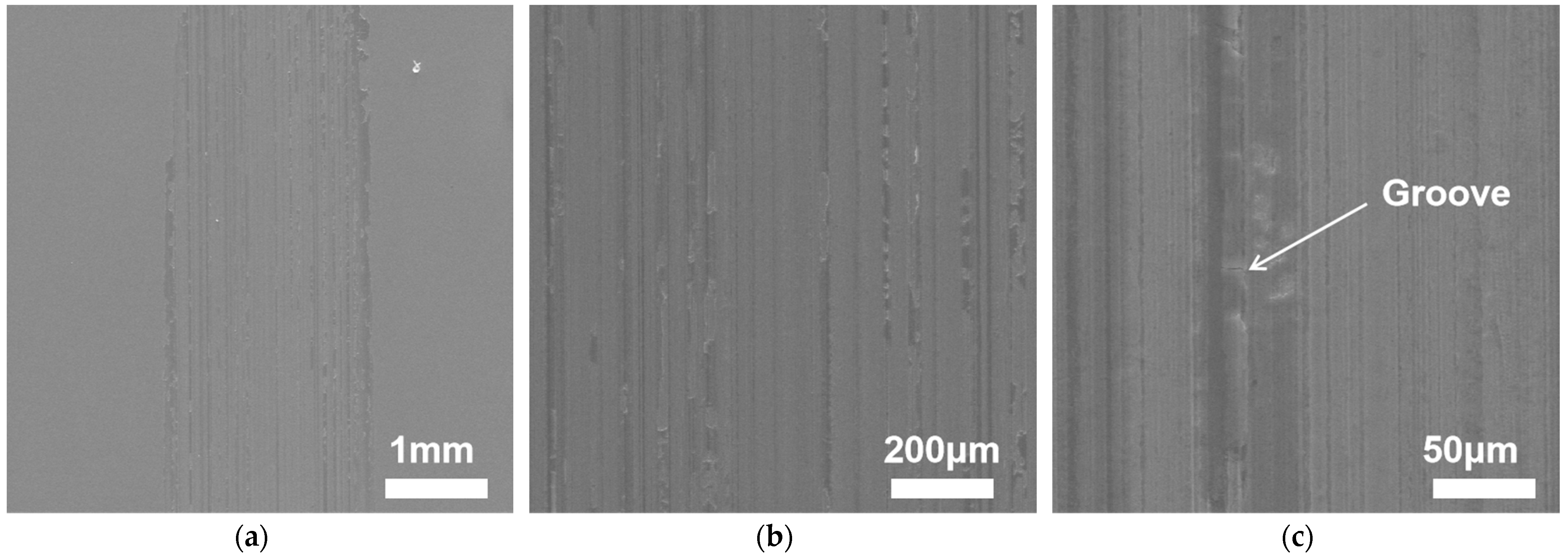
The SEM image of the Fe-based alloy coating at the end of the experiment is shown in Figure 5. From the figure, it can be observed that the wear marks are elongated and the wear is relatively slight. In the observation under high magnification, it can be found that the wear surface appears as a dark gray elongated area with a small amount of light gray area; this is due to the fact that the dark gray area is the unpeeled area, and the fresh surface that leaks out after peeling becomes the light gray area. Because of the high hardness of the Fe-based alloy coating, it has slight wear and no large plow grooves. It has an even distribution of abrasion marks.
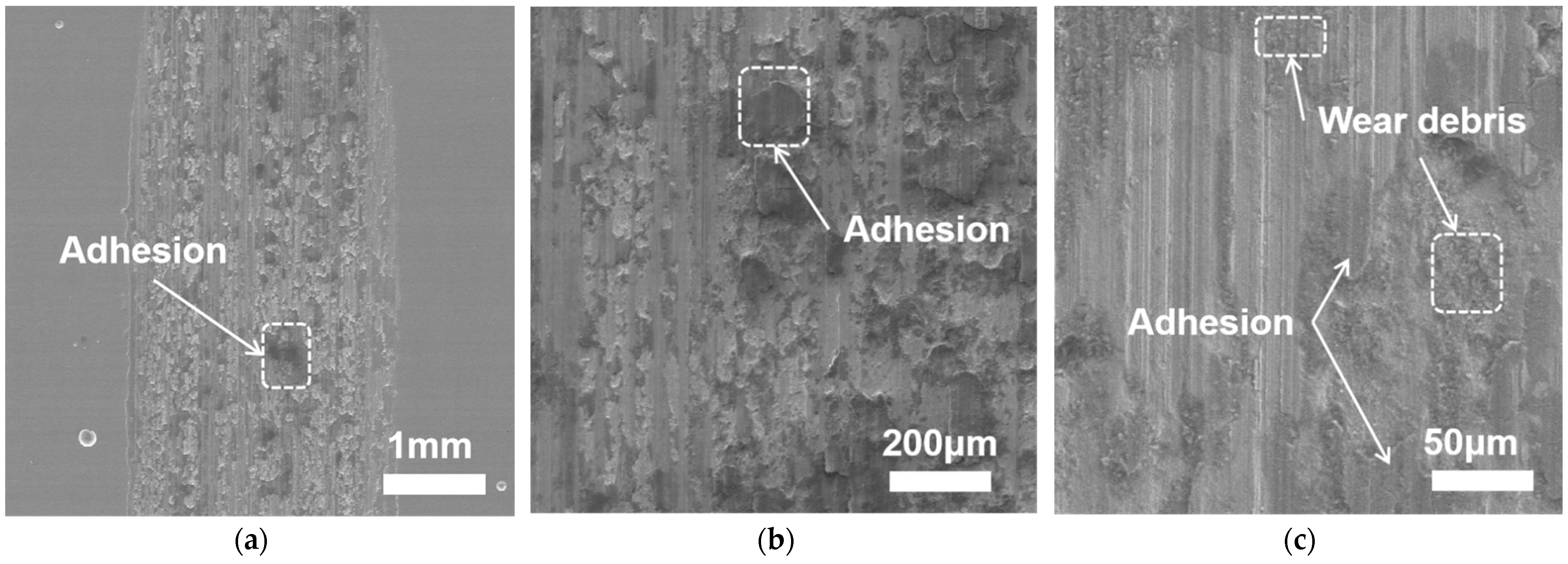
Figure 6 shows the SEM image of the Ni-based alloy coating, from which it can be found that the coating surface shows shallow furrows and material transfer due to adhesion. In Figure 6, there is a large amount of adhesion on the wear surface, as well as a bump. This is due to the low hardness of the Ni-based alloy coating and the increase in temperature during the friction process, which has made the Ni element in the alloy coating under high-temperature environment and the impact on the performance, resulting in a decrease in performance, leading to a large amount of mottling [12]. The abrasion marks can be found to be clearer under high magnification, which can be seen due to the generation of adhesion. During the friction experiment, the migration of substances has been the alloy coating, resulting in the formation of mottled bumps.
From 
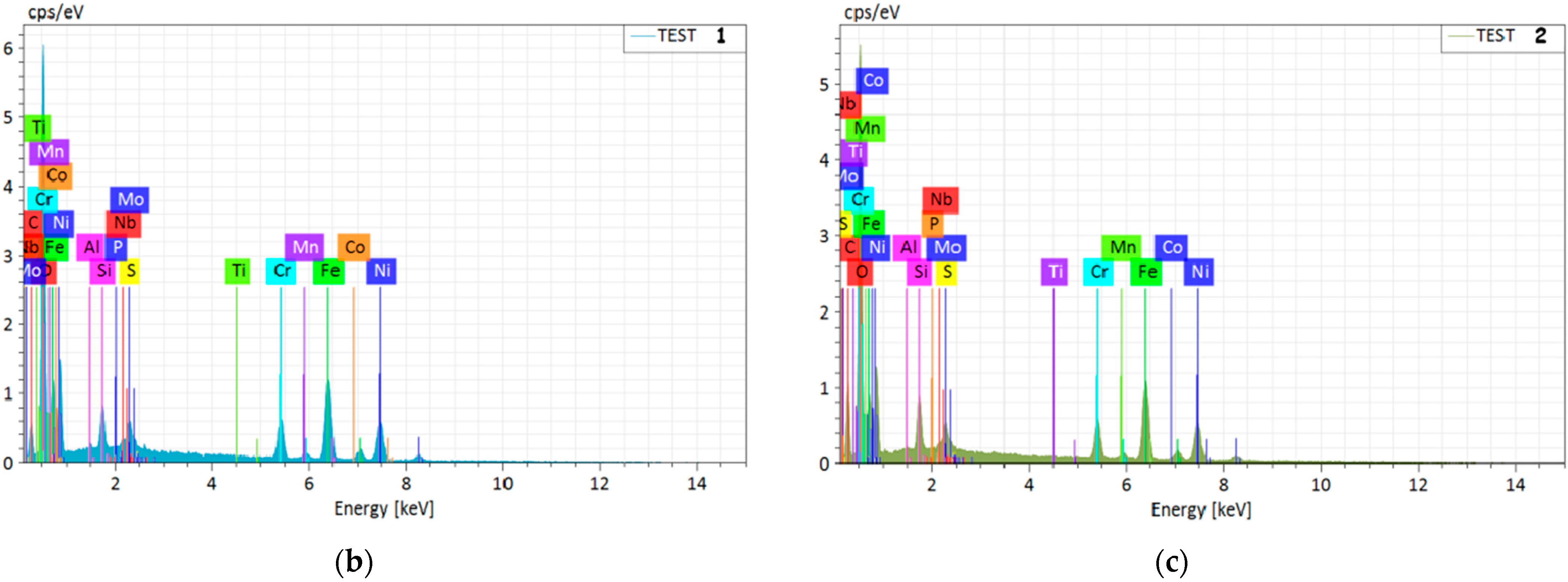
Table 6, it can be found that the two alloys have a higher percentage of O atoms, indicating that the coatings were oxidized. In 
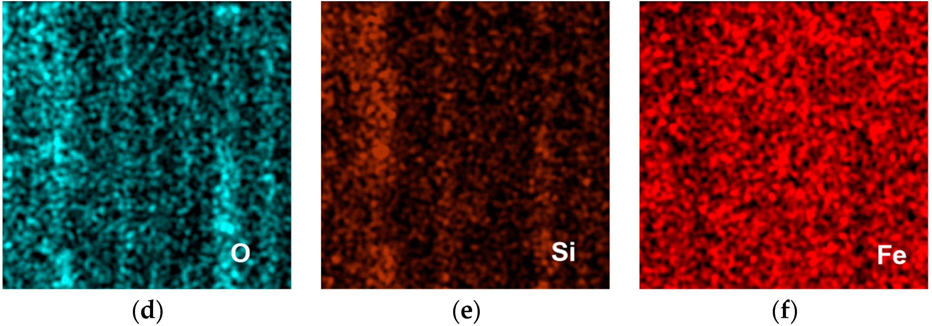
Figure 7, the oxygen atom content of the Fe-based is 22.26%. The content of iron atoms is 48.98%. It can be seen that the dark gray area in Figure 7a gathers oxygen atoms. It was oxidized when it was worn, and the degree of oxidation is less. From Table 6, the content of the Si element is 3.52%, and the Si element is used to improve the performance of the alloy in the coating. As B and Si are slagging elements, these elements can form carbides and borides with the C and Cr elements in the coating [13]. From Figure 7, the wear of it is more even and the wear marks are clear. In Figure 8, the oxygen atom content of the Ni-based reaches 32.97%, proving that the dark gray area is generated by oxygen massive compounds due to the presence of the Fe elements in the alloy coating of the Ni-based, which is due to the migration of elements. In the friction experiment, the back-and-forth motion of the friction substrate made the Fe elements in the matrix transfer to the alloy coating through the friction substrate. While generating a chemical reaction with the O elements, the generated oxide adheres to the coating to produce adhesion.
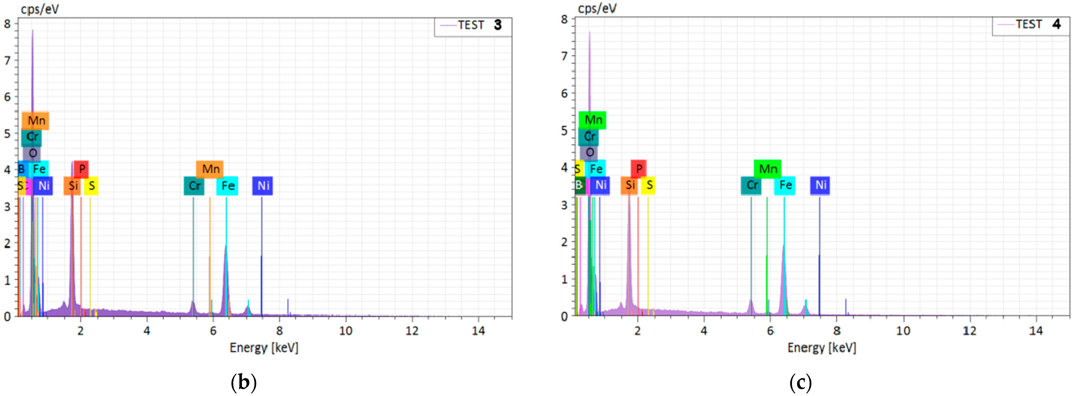
Next is the SEM image analysis of the Fe-based matrix part, and from Figure 9 it can be found that dark gray areas and larger light gray areas are formed on the worn surface of the sample. The dark gray area is the unpeeled area, and the light gray area was formed after shedding to reveal the fresh surface. EDS energy spectrum analysis was performed on the area. The results of the analysis are shown in Table 7.
After EDS image analysis, the highest O content can be found in the Fe-based matrix, reaching 39.26%. During the friction process, the substrate part reacted chemically with O in the air as well as with moisture. Moreover, oxides were produced, making the oxygen content in the matrix increase. At the same time, the generation of oxides caused certain flaking of the originally dark gray area to become a light gray area. As can also be seen from Figure 9, the content of the O element in the light gray area is less than the content in the dark gray area. The Fe-based matrix and Cr alloying elements have a high affinity for the O elements, which can easily cause oxidation during the melting and cladding process [14]. During the experiments, the surfaces were worn to expose fresh surfaces, thus making the oxidation severe and generating a large amount of adhesion. 
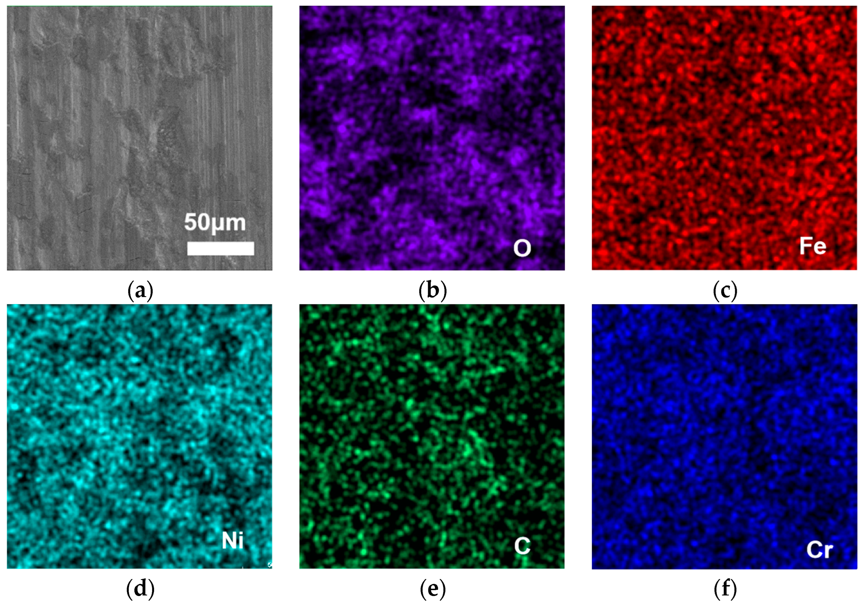
Figure 9 shows the SEM image of the Ni-based matrix. The organization of the Ni-based matrix is relatively less oxidized, and the wear marks are relatively clear and uniform. Due to the easy combination of Cr, Fe, and Mo with C to form carbides, in the melt-clad layer, these elements are transferred, allowing the wear resistance of the matrix to be enhanced. Cr and Fe are easy to form the solid solution with the Ni elements, thus improving the wear resistance and oxidation resistance of the matrix. Although the content of the matrix O atoms in the Ni-based reached 20.63%, the oxidation of the matrix was also suppressed [15].
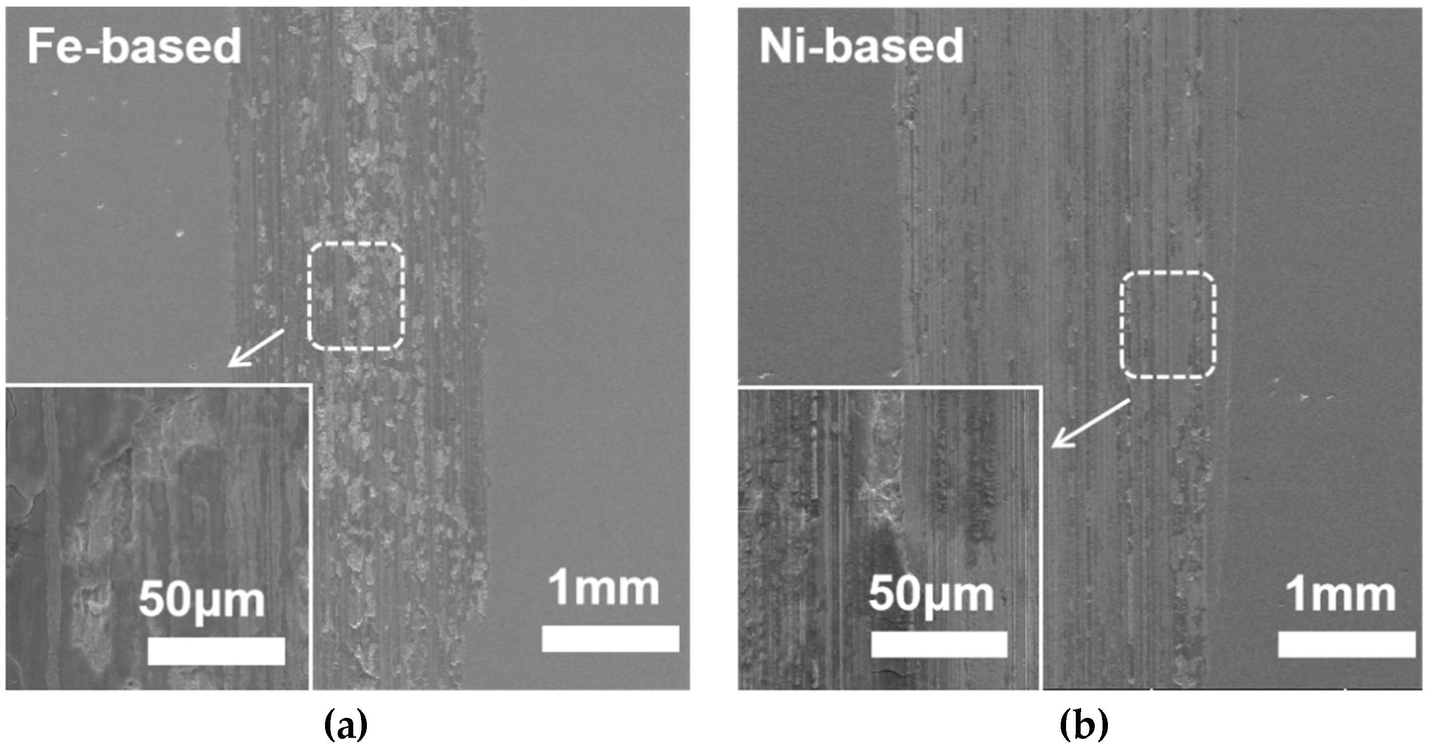
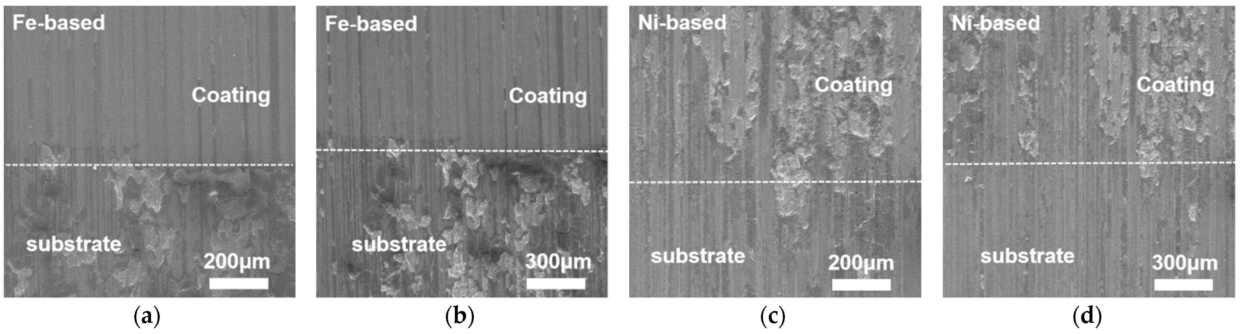
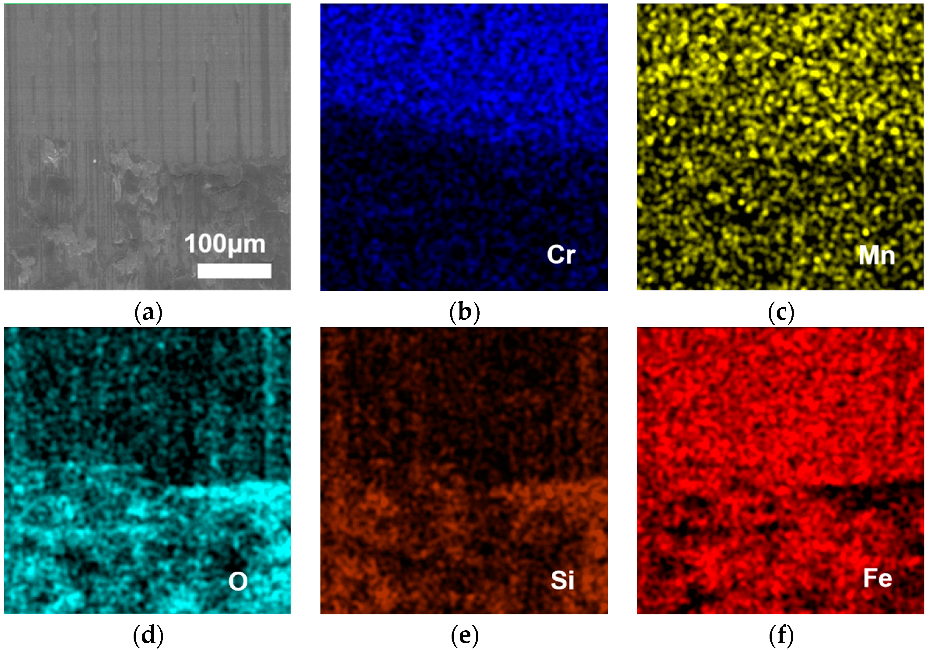
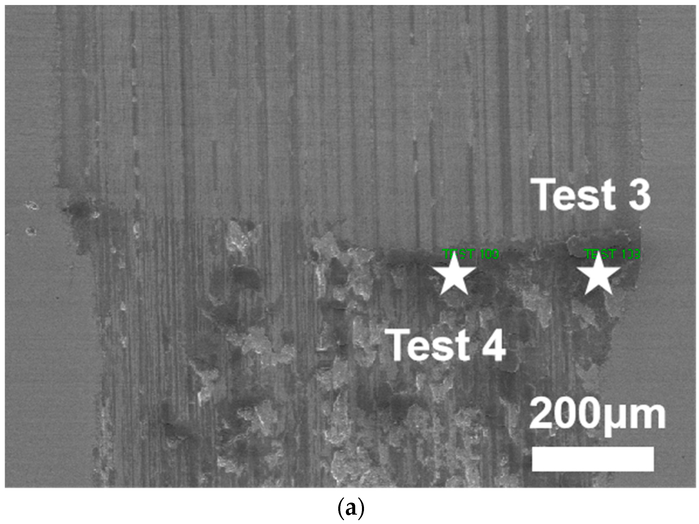
Figure 10 shows the SEM images of the interface between the two alloy coatings and the substrate. The difference between the Fe-based alloy coating and the substrate is obvious, as the coating has uniform and detailed abrasion marks, while the substrate part has many adhesions and a large number of dark gray areas and light gray areas, which were analyzed by EDS and found to have a high atomic content of the O elements in the dark gray areas. From Figure 11, the EDS image shows that the O elements of the Fe-based alloy coating are distributed in an elongated pattern, while the matrix part is distributed in a large irregular pattern, and the dark gray areas are accompanied by the distribution of the Si elements.
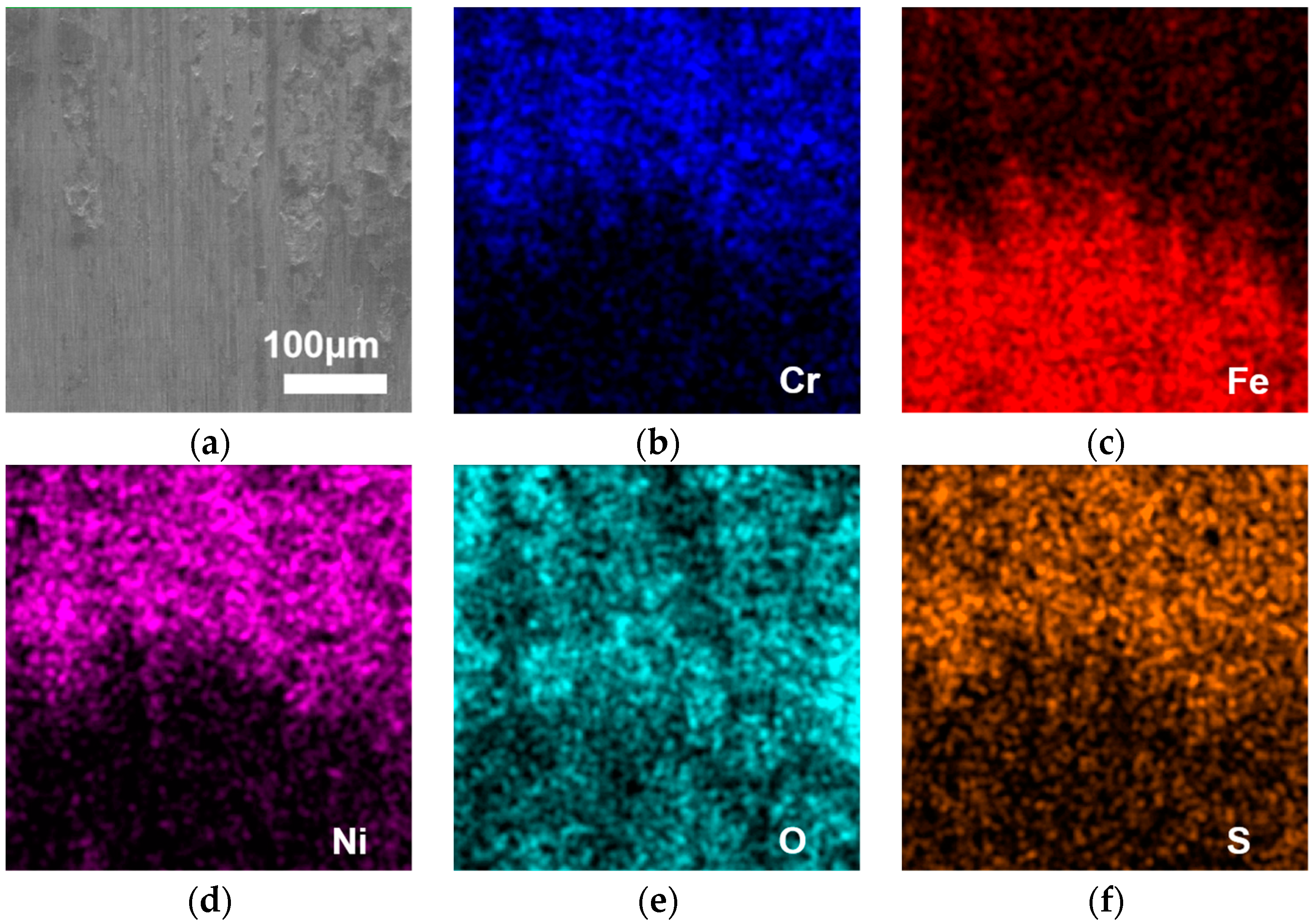
The difference between the Ni-based alloy coating and the substrate is relatively small. At the interface, there is no very obvious demarcation line. However, as can be seen in Figure 10, there are adhesions on the Ni-based layer that is light gray. Figure 12 is the Ni-based interface EDS images. From 
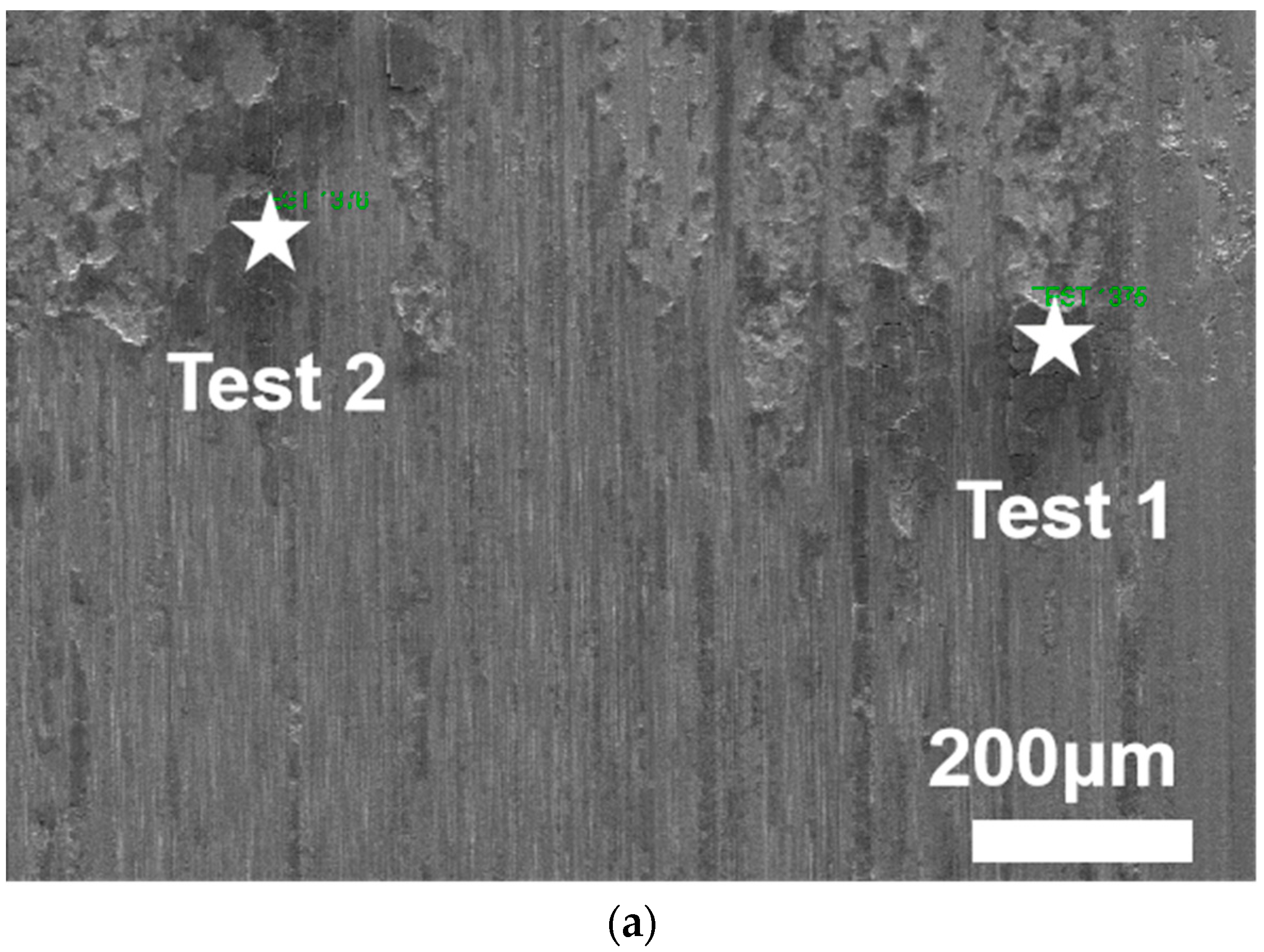
Figure 13, two points in the dark gray area were taken for the EDS analysis. From Table 8, it can be found that the dark gray region is the one with the largest proportion of O atoms, reaching 56.18% and 50.44%. The proportion of the C elements is also relatively large, which proves that the adhesion contains oxides and carbides. It proves that this region undergoes severe oxidative wear during frictional wear, forming a layer of oxide film on the wear surface, which also indicates at the same time that the oxide film can reduce wear and achieve the effect of wear reduction [16]. The surface of the area where the exfoliation occurred is relatively smooth, indicating that the fresh surface exposed after exfoliation has not been subjected to further wear from abrasive chips or frictional sub-materials.
From Figure 14, two points in the dark gray area were taken for the EDS analysis. The EDS point scan of the Fe-based interface is shown in Table 9, and the analysis of the results shows that the oxygen content in this region is significantly increased, indicating more intense oxidative wear. At the same time, the surface of the substrate part is subjected to secondary wear after flaking off during wear, which makes the wear intensify and the wear rate increase. The generated swarf is squeezed into the friction track by the friction and comes into contact with the fresh surface under a certain load, thus causing the fresh surface to participate in the wear process and wear more severely. In addition, the flaked area also interacts with the frictional sub and is subjected to cutting forces, resulting in wear and the generation of a large number of oxides [17].

3.2. Physical Phase Analysis of the Coating

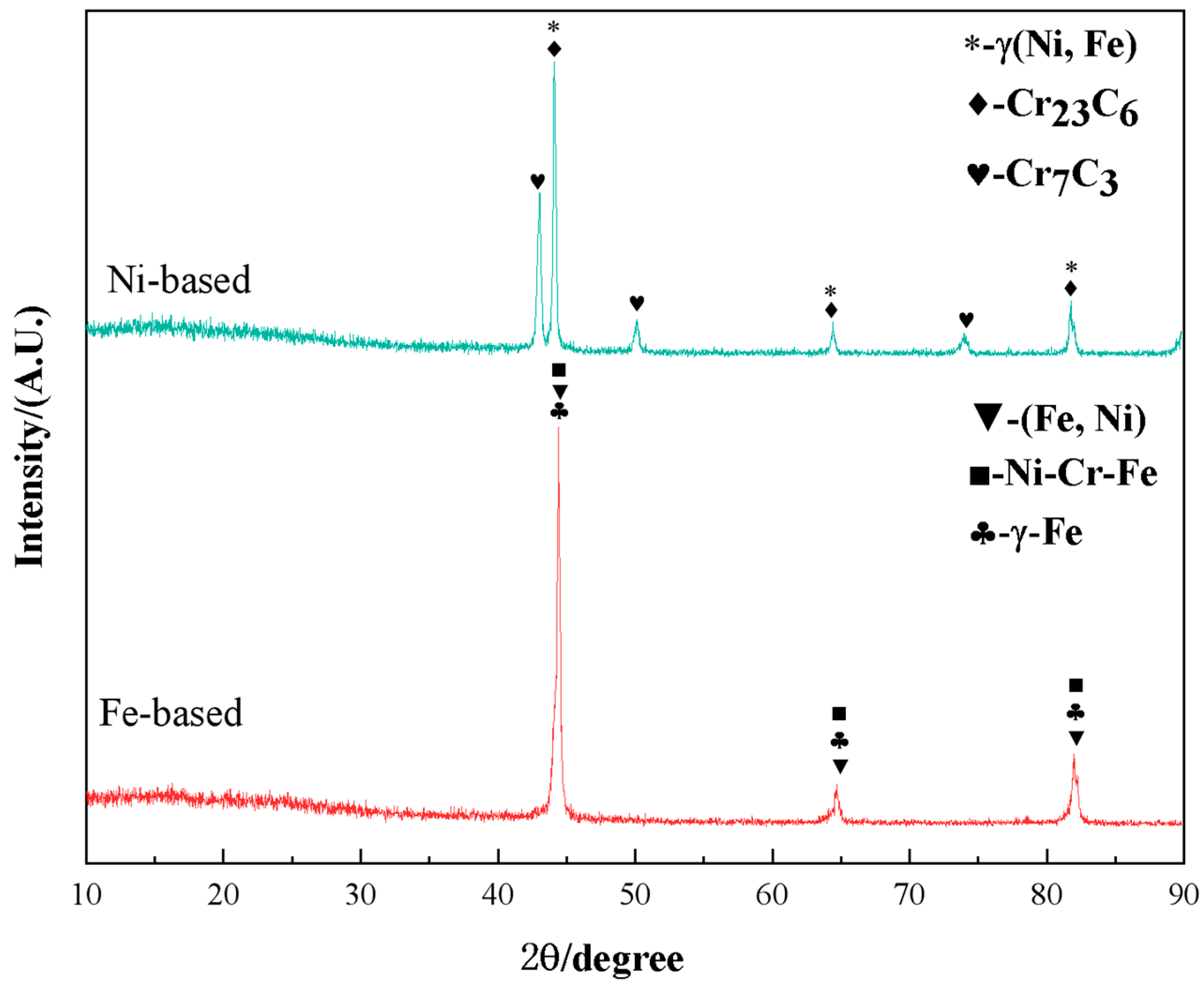
Figure 15 shows the X-ray diffraction (XRD) patterns of the Ni-based and Fe-based alloy coatings, respectively. Combined with the EDS analysis results in Table 6, it can be found that the Ni-based alloy coatings may contain γ(Ni, Fe), Cr23C6, Cr7C3, and other phases, and the Fe-based alloy coatings may contain γ-Fe, (Fe, Ni), Ni-Cr-Fe and other phases.
When the laser-cladding tests were performed on both specimens, the elements between the heated substrate and the cladding layer underwent a permeation phenomenon or exchanged with each other. This may lead to the fact that the elements will combine and thus the content of the elements will change [18].
In the Ni-based alloy coatings, the main element of the molten material powder is Ni, while the higher content of the matrix is Fe. The Fe element diffuses from the region of the matrix to the alloy coating, leading to an increase in the content of the Fe element in the coating. While other elements are less present due to the presence of less content, the change is not obvious due to the diffusion of the elements that occur during laser melting and the insensitivity of the test equipment [19]. The main element of the Fe-based alloy coating and the substrate is Fe, and the diffusion of the elements is not obvious when laser cladding is performed, which is equivalent to no diffusion of the elements, so the change of the elements is small.
From the energy spectrum EDS analysis of the two specimens in Table 6, it can be concluded that the Ni-based alloy coating mainly contains Ni, Fe, C, and Cr, which are the main constituent elements of the Ni-based alloy coating. It also contains small amounts of Co, Mo, S, and Nb, etc. The main physical phases are γ(Ni, Fe), Cr7C3, and Cr23C6. During the laser-cladding process, because the melt pool is generated on the surface of the substrate, in the initial solidification stage, a large amount of austenite is precipitated due to the high temperature. Because of the rapid solidification characteristics of laser cladding, the cooling rate is very rapid, up to 10 °C/s, resulting in a large number of austenite phases without phase transformation, which is retained at room temperature. The main phases in the organization of the Fe-based cladding layer are the (Fe, Ni) solid solution and the Ni-Cr-Fe solid solution because the alloy powder is composed of Fe-Ni-Cr elements, which are all third-period elements with similar atomic radii and can replace each other, so it is easy to form the Fe-Ni-Cr solid solution [20].

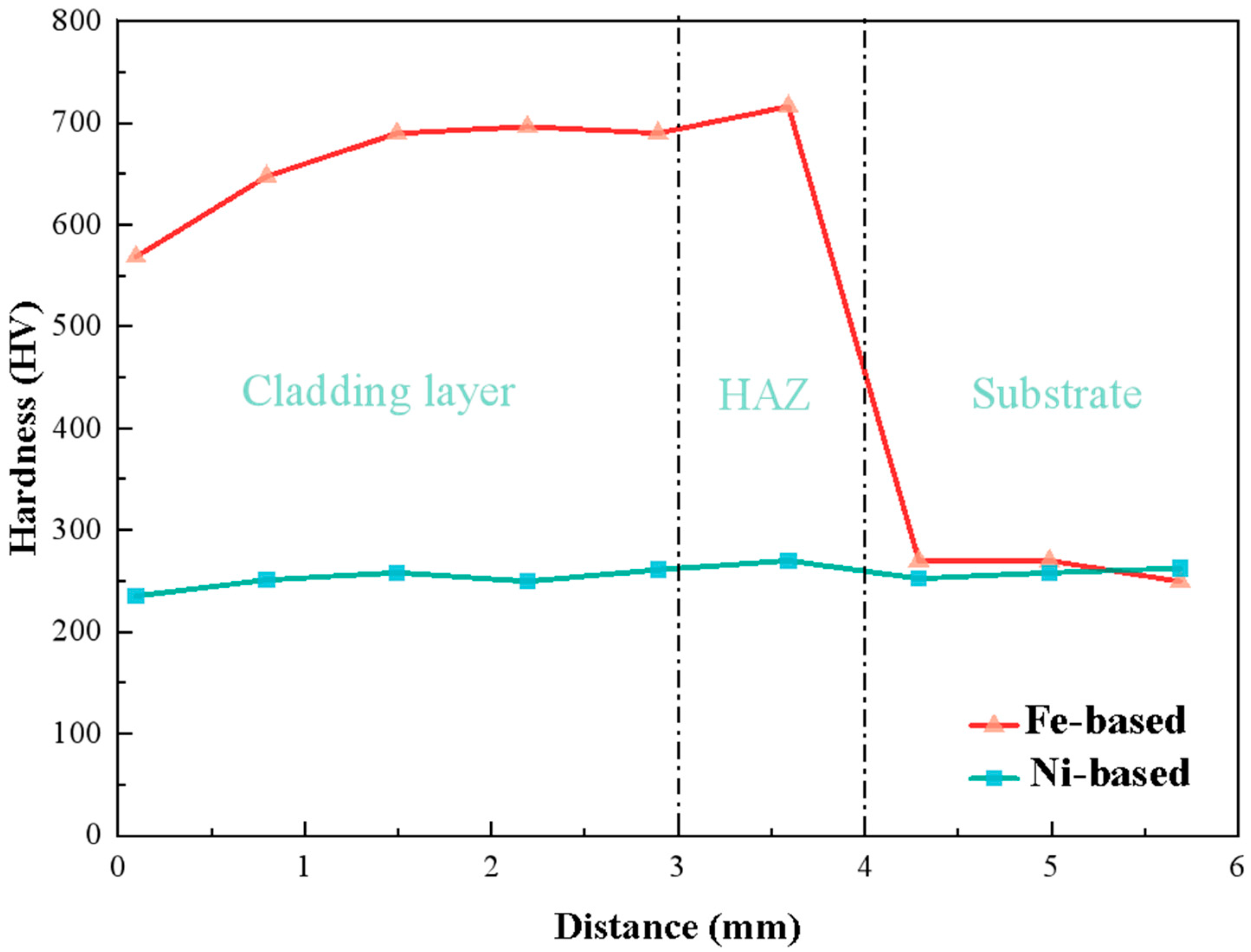
3.3. Microhardness Analysis

The hardness of a laser-fused coating has a profound effect on the frictional wear properties of the coating and is one of the main factors in frictional wear performance. Using a Vickers hardness tester, the hardness of the molten sample is measured. The parameters of the Vickers hardness tester measurement were specifically: load 200 gf, loading time 15 s, objective magnification 40×, 9 points were selected for each specimen, respectively, and the distance interval between points was 0.7 mm.
Figure 16 shows the distribution curve of the microhardness of the wear surface of the iron-based and the nickel-based. It is obvious from the figure that 4~5.5 mm is the hardness of the substrate. The microhardness of the substrate is about 260 HV0.7, and from 0~3 mm is the hardness of the fused layer. The hardness of the Fe-based alloy coating is higher than the hardness of the Ni-based alloy coating. The cross-sectional hardness of the the Fe-based coating reaches a maximum of about 715 HV0.7, which is about 2.8 times higher than the microhardness of the ER9 substrate. While the Ni-based alloy coating hardness microhardness fluctuates less, the distribution is more uniform. The average hardness is maintained at about 250 HV0.7. 3~4 mm called heat-affected zone. The hardness of the Ni-based increases slightly in the HAZ, but the change is not obvious, while the Fe-based hardness value will drop rapidly to about 400 HV0.7 in the part near the substrate. This is due to the difference in the material composition of the substrate and the clad layer as well as the fast melting and fast cooling characteristics of the cladding process, which makes the hardness drop rapidly. When the wheel steel is in the cladding process, the laser beam is irradiated on the surface of the clad material and therefore melts and solidifies rapidly. In the experiment of laser cladding, due to the presence of heat transfer, the heat in the solution is transferred to the substrate, which causes the temperature to plunge, thus cooling rapidly and forming a bonding zone with the substrate material, also known as the heat-affected zone [21]. The hardness of the Fe-based alloy coating itself is about to be greater than the hardness of the substrate, in the process of cladding the grain refining, which plays the role of solid-solution strengthening and forms some carbides. These carbides have a hard phase, which makes the hardness of the clad layer significantly higher than that of the substrate. During the cladding process, after the solution solidifies, the solution has to transfer a large amount of heat to the substrate through heat transfer, which makes the heat-affected zone produce a quenching effect locally because of the presence of high temperature, thus making the hardness of the heat-affected zone increase and also become higher than that of the substrate [22].

3.4. Analysis of the Wear Resistance of the Coating

The wear resistance of the laser-clad layer was characterized, using its coefficient of friction and wear amount in the test. The friction coefficient was measured by the MFT-EC4000 reciprocating electrochemical friction and wear tester, and the experimental results are shown in Table 10.
Figure 17 shows the variation curves of the friction coefficients of the Fe-based and Ni-based for the same time as well as parameters. From the figure, it can be found that the friction coefficient of the specimens of the Fe-based is high in the running-in from 0 to 34 min. It does not differ much from the previous running-in in the stable wear stage from 35 to 60 min, both of which are maintained at about 0.5μ. The friction coefficient of the Ni-based is smaller than that of the Fe-based in the grinding stage, but it is the same as that of the Fe-based in the stable wear stage. The friction coefficient of the Ni-based floated more, and the average friction coefficient was 0.327μ compared with 0.331μ of the Fe-based. The Ni-based did not maintain a stable wear state in the wear phase.
The analysis concluded that the Fe-based cladding layer is not easy to produce abrasive chips due to its higher hardness and uniform organization. The wear mechanism is mainly abrasive wear because the abrasive chips are harder and less likely to adhere to the material surface [23]. The main wear mechanism of the Ni-based surface is mainly adhesive wear, while the hardness of the relative substrate is low and it is easier to produce abrasive chips, so the friction coefficient is smaller. The hardness of the Ni-based cladding layer is not much different from that of the substrate, so both are easy to produce abrasive chips. Shear occurs between the abrasive chips and the specimen surface with the problem of adhesion and tearing between the chips themselves. The non-stop repetitive force intensifies the wear and causes it to enter the stable wear phase relatively quickly [24].

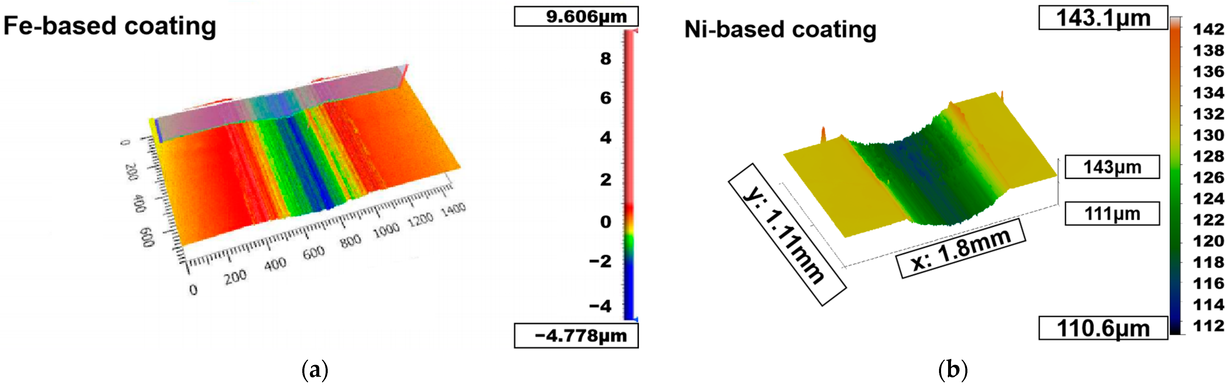
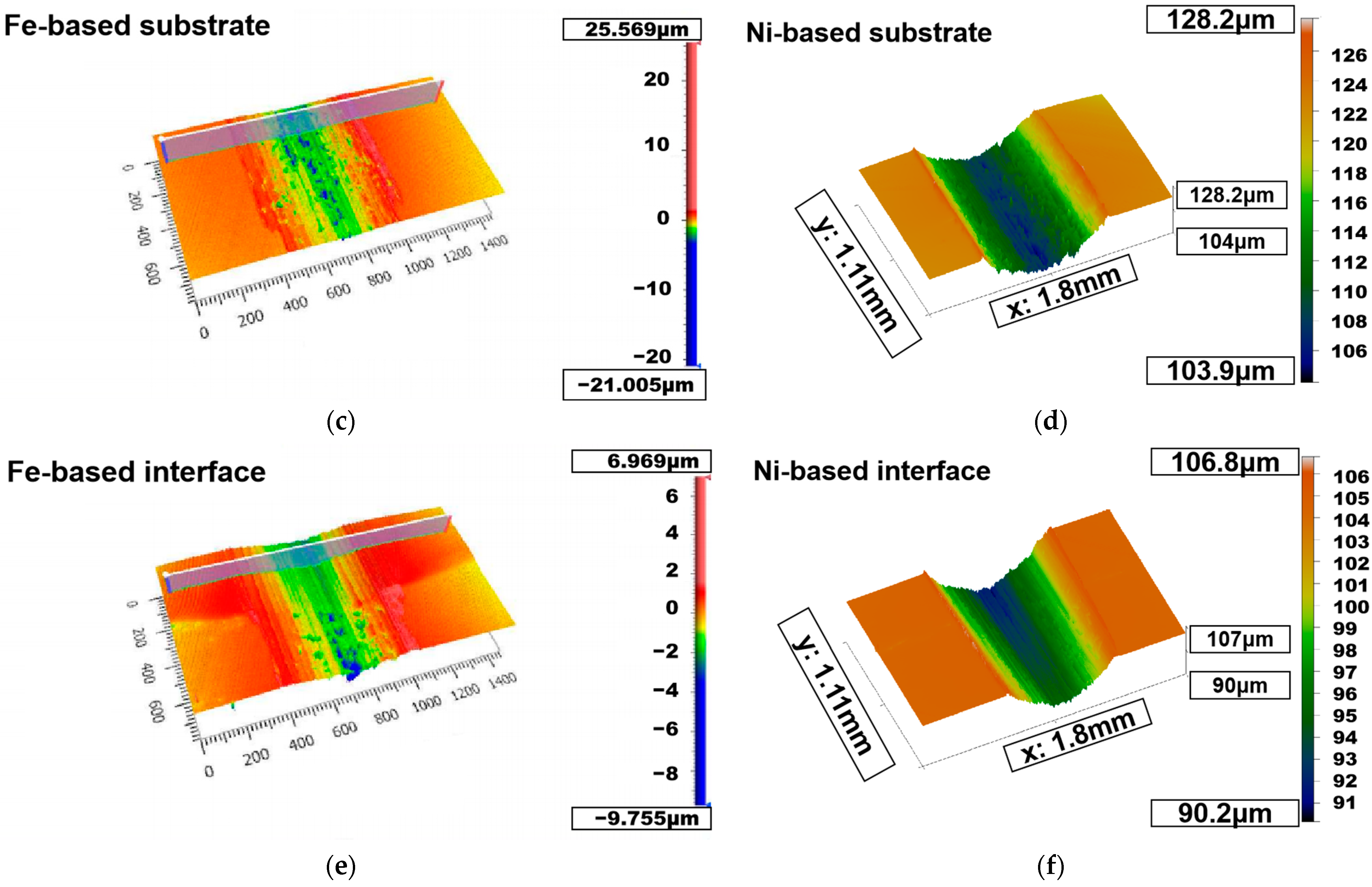
3.5. Three-Dimensional Morphological Analysis

The 3D wear pattern of each specimen under dry friction conditions is shown in 
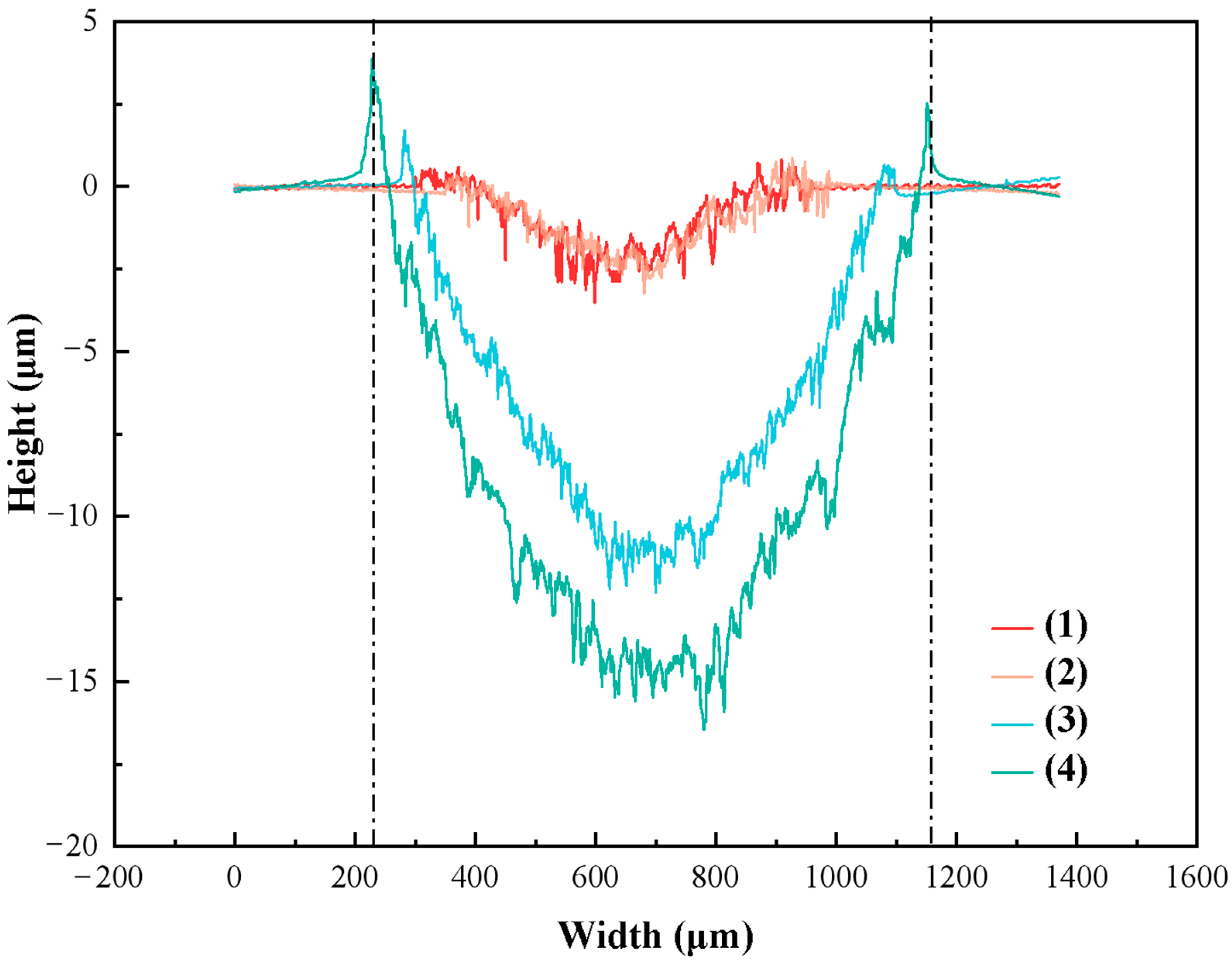
Figure 18, from which it can be found that the width of the wear part of the Fe-based is shorter than that of the Ni-based coating part, while the wear depth is also greater for the Ni-based. This is mainly due to the higher hardness of the Fe-based alloy coating, while in comparison, the Ni-based alloy coating has lower hardness and wears more easily, and the depth and width of wear are also larger. Figure 19 shows that the wear width of the Ni-based alloy coating and the substrate is about 1000 μm, and the wear width of the Fe-based specimen is about 500 μm.
Moreover, it can be found from Figure 18 that the wear depths of the two specimens are different. From the shades of color in the 3D morphology, it can be judged that the blue area of the Fe-based material is lighter, indicating that the wear of the Fe-based material is low and the depth is also low. On the contrary, the Ni-based material is not only darker in the blue area, but also wider in the green area, indicating that the Ni-based wear is not only severe in the transverse direction with more intense wear in the longitudinal direction. The deepest wear depth of the Ni-based material is about 17 μm, and the wear depth of the Ni-based matrix part is about 13 μm. The deepest wear depth of the matrix and alloy coating part of the Fe-based material is about 3.5 μm, and the wear degree of the Ni-based is about 4 times deeper than the Fe-based.
The analysis concluded that the wear area at the Fe-based interface was lighter in color, indicating lower wear and that there were pits and bumps on the substrate surface due to oxides and adhesions on the substrate. The Ni-based interface is much smoother and more uniform than the Fe-based, but there is a slight mottling above the interface, which is at the alloy coating. Compared with the matrix part, the wear width of the Ni-based alloy coating part is slightly wider. The wear depth at the interface of the two materials also differs significantly. The wear depth of the Fe-based is green, indicating slight wear, while the wear depth of the Ni-based is a large blue. The depth and wear degree are deeper than that of the Fe-based, which is mainly due to the characteristics of the Ni-based material itself. In addition, the difference between the hardness of the base and the hardness of the Ni-based alloy coating is small, so the wear marks are deeper. The Fe-based alloy coating, on the other hand, has a solid-solution strengthening, as well as a preheating post-treatment, which makes the hardness increase and lets the wear resistance improve. At the same time, because of the friction test, due to the back-and-forth movement of the friction sub, it makes a slight transfer of the elements in the coating, so that the Fe-based substrate has a protective effect and suffered less wear [25,26].

4. Conclusions

(1) Ni-based and Fe-based alloy coatings were prepared on the surface of ER9 material of subway wheels using laser-melting technology, and the obtained coatings were dense in an organization and free from defects such as cracks and pores. The interface between the joint and the substrate is visible, and the two coatings show good metallurgical bonding. The Ni-based phases mainly consist of γ(Ni, Fe), Cr7C3, and Cr23C6. Fe, Cr, and Ni are all elements of the fourth cycle of the periodic table and are transition elements with similar atomic structures. Cr in the Ni-based alloys can improve inter-atomic bonding and play a role in solid-solution strengthening. The cladding zone contains the carbide of Cr and some Ni phases. The existence of the solid solution and the carbide hard phase in the organization of the clad layer has improved the strength and toughness of the material.
The Fe-based coatings mainly contain γ-Fe, (Fe, Ni), (Fe-Cr-Ni) solid solution, and other phases. Fe-based materials mainly consist of austenite (γ-Fe), γ(Fe, Ni) solid solution, and Fe-Ni-Cr solid solution. During the laser processing, the laser melts the metal powder and forms a melting pool on the surface of the substrate. At the early stage of solidification, a large amount of the austenite phase and the γ(Fe, Ni) solid solution would be precipitated from the liquid state. Due to the rapid solidification characteristics of the laser melting, the cooling rate is extremely fast, up to 10/s °C, resulting in a large number of austenite phases that were too late to undergo phase transformation, and hence were retained at room temperature. In addition, Fe, Ni, and Cr are the main components of the alloy powder, and they are all third-period elements with similar atomic radii and can be substituted for each other, so it is easy to form the Fe-Ni-Cr solid solution.
(2) At the end of the friction test, the Ni-based coating showed a more serious oxidation phenomenon, and the main wear mechanism was adhesive wear. The hardness of the Fe-based coating reaches a maximum of 715 HV0.7, which is 2.86 times higher than that of the base material (250HV). The maximum hardness of the Ni-based coating is 268.4 HV0.7. The friction coefficient of the Ni-based floated more, and the average friction coefficient was 0.327μ compared with 0.331μ of Fe-based. The maximum friction coefficient of the Fe-based was 0.569μ, and the maximum friction coefficient of the Ni-based was 0.536μ. The friction coefficient of the Fe-based coating is higher than that of the Ni-based coating, and the average friction coefficient difference is only 0.004, while the wear width of the Fe-based specimen is about 500μm. The wear depth of the Fe-based coating is about 3.5 μm, and the wear degree of the Ni-based coating is about 4 times deeper than the Fe-based, which is 13 μm.
(3) The Fe-based coating, due to the presence of the solid-solution phase, formed solid-solution strengthening. At the same time, due to the preheating of the melted coating, the local quenching effect occurred, and the wear resistance and hardness of the tissue were enhanced. The Ni-based coating in the high-temperature performance was general, while the hardness and friction properties were also lower. Meanwhile, the economic efficiency of Ni-based was lower.
(4) This experiment shows that laser-cladding technology can improve the properties of wheels such as wear resistance and hardness. In addition, it is demonstrated that the alloy powder can lead to more significant performance improvement when the alloy coating is similar to the base material. Lastly, considering the optimal wear relationship between the wheel and the rail, as well as the high hardness and wear resistance of the Fe-based coating, Fe-based coating is obviously not suitable for the cladding of wheels. The future research can be conducted from selecting the appropriate process treatment to make the Fe-based more compatible with the laser cladding repair of wheels.

Author Contributions

Conceptualization, Q.X.; Methodology, W.Y.; Software, B.Z.; Validation, B.Z. and W.Y.; Formal Analysis, B.Z.; Investigation, B.Z.; Resources, B.Z.; Data Curation, B.Z.; Writing-Original Draft Preparation, B.Z.; Writing-Review & Editing, Q.X. and W.Y.; Visualization, B.Z.; Supervision, Q.X. and W.Y.; Project Administration, Q.X.; Funding Acquisition, W.Y. All authors have read and agreed to the published version of the manuscript.

Funding

This research received no external funding.

Institutional Review Board Statement

Not applicable.

Informed Consent Statement

Not applicable.

Data Availability Statement

All data that support the findings of this study are included within the article.

Conflicts of Interest

The authors declare no conflict of interest.

References

  1. Wang, W.J.; Fu, Z.K.; Cao, X.; Guo, J.; Liu, Q.Y.; Zhu, M.H. The role of lanthanum oxide on wear and contact fatigue damage resistance of laser cladding Fe-based alloy coating under oil lubrication condition. Tribol. Int. 2016, 94, 470–478. [Google Scholar] [CrossRef]
  2. Soleimani, H.; Moavenian, M. Tribological Aspects of Wheel–Rail Contact: A review of wear mechanisms and effective factors on rolling contact fatigue. Urban Rail Transit. 2017, 3, 227–237. [Google Scholar] [CrossRef] [Green Version]
  3. Wang, W.J.; Guo, J.; Liu, Q.Y.; Zhu, M.H. Effect of laser quenching on wear and damage of heavy-haul wheel/rail materials. Proc. Inst. Mech. Eng. Part J. Eng. Tribol. 2013, 228, 114–122. [Google Scholar] [CrossRef]
  4. Wang, W.J.; Hu, J.; Guo, J.; Liu, Q.Y.; Zhu, M.H. Effect of laser cladding on wear and damage behaviors of heavy-haul wheel/rail materials. Wear 2014, 311, 130–136. [Google Scholar] [CrossRef]
  5. Lewis, S.R.; Fretwell-Smith, S.; Goodwin, P.S.; Smith, L.; Lewis, R.; Aslam, M.; Fletcher, D.I.; Murray, K.; Lambert, R. Improving rail wear and RCF performance using laser cladding. Wear 2016, 366–367, 268–278. [Google Scholar] [CrossRef]
  6. Lewis, S.R.; Lewis, R.; Fletcher, D.I. Assessment of laser cladding as an option for repairing/enhancing rails. Wear 2015, 330–331, 581–591. [Google Scholar] [CrossRef]
  7. Lewis, S.R.; Lewis, R.; Goodwin, P.S.; Fretwell-Smith, S.; Fletcher, D.I.; Murray, K.; Jaiswal, J. Full-scale testing of laser clad railway track; Case study—Testing for wear, bend fatigue and insulated block joint lipping integrity. Wear 2017, 376–377, 1930–1937. [Google Scholar] [CrossRef]
  8. Chen, H.; Ban, T.; Ishida, M.; Nakahara, T. Adhesion between rail/wheel under water lubricated contact. Wear 2002, 253, 75–81. [Google Scholar] [CrossRef]
  9. Xu, X.; Mi, G.; Chen, L.; Xiong, L.; Jiang, P.; Shao, X.; Wang, C. Research on microstructures and properties of Inconel 625 coatings obtained by laser cladding with wire. J. Alloy. Compd. 2017, 715, 362–373. [Google Scholar] [CrossRef]
  10. Hu, G.; Yang, Y.; Sun, R.; Qi, K.; Lu, X.; Li, J. Microstructure and properties of laser cladding NiCrBSi coating assisted by electromagnetic-ultrasonic compound field. Surf. Coat. Technol. 2020, 404, 126469. [Google Scholar] [CrossRef]
  11. Jiang, C.; Zhang, J.; Chen, Y.; Hou, Z.; Zhao, Q.; Li, Y.; Zhu, L.-X.; Zhang, F.-Y.; Zhao, Y. On enhancing wear resistance of titanium alloys by laser cladded WC-Co composite coatings. Int. J. Refract. Met. Hard Mater. 2022, 107, 105902. [Google Scholar] [CrossRef]
  12. Guo, H.-M.; Wang, Q.; Wang, W.-J.; Guo, J.; Liu, Q.-Y.; Zhu, M.-H. Investigation on wear and damage performance of laser cladding Co-based alloy on single wheel or rail material. Wear 2015, 328–329, 329–337. [Google Scholar] [CrossRef]
  13. Janicki, D. Laser cladding of Inconel 625-based composite coatings reinforced by porous chromium carbide particles. Opt. Laser. Technol. 2017, 94, 6–14. [Google Scholar] [CrossRef]
  14. Wang, W.J.; Guo, H.M.; Du, X.; Guo, J.; Liu, Q.Y.; Zhu, M.H. Investigation on the damage mechanism and prevention of heavy-haul railway rail. Eng. Fail. Anal. 2013, 35, 206–218. [Google Scholar] [CrossRef]
  15. Lai, Q.; Abrahams, R.; Yan, W.; Qiu, C.; Mutton, P.; Paradowska, A.; Fang, X.; Soodi, M.; Wu, X. Effects of preheating and carbon dilution on material characteristics of laser-cladded hypereutectoid rail steels. Mater. Sci. Eng. A 2018, 712, 548–563. [Google Scholar] [CrossRef]
  16. Liu, Y.; Wu, Y.; Ma, Y.; Gao, W.; Yang, G.; Fu, H.; Xi, N.; Chen, H. High temperature wear performance of laser cladding Co06 coating on high-speed train brake disc. Appl. Surf. Sci. 2019, 481, 761–766. [Google Scholar] [CrossRef]
  17. Raahgini, C.; Verdi, D. Abrasive wear performance of laser cladded Inconel 625 based metal matrix composites: Effect of the vanadium carbide reinforcement phase content. Surf. Coat. Technol. 2022, 429, 127975. [Google Scholar] [CrossRef]
  18. Raghuram, H.; Katsich, C.; Pichelbauer, K.; Koschatzky, K.; Gachot, C.; Cihak-Bayr, U. Design of wear and corrosion resistant FeNi-graphite composites by laser cladding. Surf. Coat. Technol. 2019, 377, 124897. [Google Scholar] [CrossRef]
  19. Zhu, Y.; Chen, X.; Wang, W.; Yang, H. A study on iron oxides and surface roughness in dry and wet wheel−rail contacts. Wear 2015, 328–329, 241–248. [Google Scholar] [CrossRef]
  20. Zhu, Y.; Lyu, Y.; Olofsson, U. Mapping the friction between railway wheels and rails focusing on environmental conditions. Wear 2015, 324–325, 122–128. [Google Scholar] [CrossRef]
  21. Fu, Z.K.; Ding, H.H.; Wang, W.J.; Liu, Q.Y.; Guo, J.; Zhu, M.H. Investigation on microstructure and wear characteristic of laser cladding Fe-based alloy on wheel/rail materials. Wear 2015, 330–331, 592–599. [Google Scholar] [CrossRef]
  22. Roy, T.; Lai, Q.; Abrahams, R.; Mutton, P.; Paradowska, A.; Soodi, M.; Yan, W. Effect of deposition material and heat treatment on wear and rolling contact fatigue of laser cladded rails. Wear 2018, 412–413, 69–81. [Google Scholar] [CrossRef]
  23. Shariff, S.M.; Pal, T.K.; Padmanabham, G.; Joshi, S.V. Influence of chemical composition and prior microstructure on diode laser hardening of railroad steels. Surf. Coat. Technol. 2013, 228, 14–26. [Google Scholar] [CrossRef]
  24. Shim, D.S.; Lee, H.; Son, Y.; Oh, W.J. Effects of pre- and post-repair heat treatments on microstructure and tensile behaviors of 630 stainless steel repaired by metal additive manufacturing. J. Mater. Res. Technol. 2021, 13, 980–999. [Google Scholar] [CrossRef]
  25. Lu, X.; Cotter, J.; Eadie, D.T. Laboratory study of the tribological properties of friction modifier thin films for friction control at the wheel/rail interface. Wear 2005, 259, 1262–1269. [Google Scholar] [CrossRef]
  26. Yu, T.; Chen, J.; Wen, Y.; Deng, Q. High temperature phase stability and wear behavior of laser clad Ta reinforced NiCrBSi coating. Appl. Surf. Sci. 2021, 547, 149171. [Google Scholar] [CrossRef]
Figure 1. Laser flexible additive manufacturing system.
Coatings 12 01561 g001
Figure 2. Laser-cladding process.
Coatings 12 01561 g002
Figure 3. Samples of cladding.
Coatings 12 01561 g003
Figure 4. Schematic diagram of friction test.
Coatings 12 01561 g004
Figure 5. Fe-based alloy coating SEM images. These three images are obtained under different microscopic multiples of the same area. (a) Wear marks of Fe-based coating at 1mm of the scale; (b) Wear marks of Fe-based coating at 200 μm of the scale; (c) Wear marks of Fe-based coating at 50 μm of the scale.
Coatings 12 01561 g005
Figure 6. Ni-based alloy coating SEM images. These three images are obtained under different microscopic multiples of the same area. (a) Wear marks of Ni-based coating at 1mm of the scale; (b) Wear marks of Ni-based coating at 200 μm of the scale; (c) Wear marks of Ni-based coating at 50 μm of the scale.
Coatings 12 01561 g006
Figure 7. Fe-based coating EDS images. (a) The image of Fe-based coating SEM; (b) The content of the B element is 4.13%; (c) The content of the Cr element is 10.14%; (d) The content of the O element is 22.26%; (e) The content of the Si element is 3.52%; (f) The content of the Fe element is 48.98%.
Coatings 12 01561 g007aCoatings 12 01561 g007b
Figure 8. Ni-based coating EDS images. (a) The image of Ni-based coating SEM; (b) The content of the O element is 32.97%; (c) The content of the Fe element is 10.54%; (d) The content of the Ni element is 21.52%; (e) The content of the C element is 22.97%; (f) The content of the Cr element is 8.41%.
Coatings 12 01561 g008
Figure 9. Fe-based and Ni-based substrate SEM images. (a) Wear marks of Fe-based substrate; (b) Wear marks of Ni-based substrate.
Coatings 12 01561 g009
Figure 10. Two coating interface SEM images. (a) The interface of Fe-based at 200 μm of the scale; (b) The interface of Fe-based at 300 μm of the scale; (c) The interface of Ni-based at 200 μm of the scale; (d) The interface of Ni-based at 300 μm of the scale.
Coatings 12 01561 g010
Figure 11. Fe-based interface EDS images. This is the interface between the substrate and the coating, and the difference in materials can be seen. The upper part is the coating, and the lower part is the substrate. The elements at the interface had migrated due to laser-cladding and friction tests. Therefore, the content of each element had some deviation. (a) The interface of Fe-based at 100 μm of the scale; (b) Distribution of Cr atom at the interface; (c) Distribution of Mn atom at the interface; (d) Distribution of O atom at the interface; (e) Distribution of Si atom at the interface; (f) Distribution of Fe atom at the interface.
Coatings 12 01561 g011
Figure 12. Ni-based interface EDS images. This is the interface between the substrate and the coating, and the difference in materials can be seen. The upper part is the coating, and the lower part is the substrate. The elements at the interface had migrated due to laser-cladding and friction tests. Therefore, the content of each element had some deviation. (a) The interface of Ni-based at 100 μm of the scale; (b) Distribution of Cr atom at the interface; (c) Distribution of Fe atom at the interface; (d) Distribution of Ni atom at the interface; (e) Distribution of O atom at the interface; (f) Distribution of S atom at the interface.
Coatings 12 01561 g012
Figure 13. Ni-based EDS spot scan. (a) The image of Ni-based interface at 200 μm of the scale.; (b) The EDS image of Test 1; (c) The EDS image of Test 2.
Coatings 12 01561 g013aCoatings 12 01561 g013b
Figure 14. Fe-based EDS spot scan. (a) The image of Ni-based interface at 200 μm of the scale; (b) The EDS image of Test 3; (c) The EDS image of Test 4.
Coatings 12 01561 g014aCoatings 12 01561 g014b
Figure 15. XRD patterns of the two samples.
Coatings 12 01561 g015
Figure 16. Microhardness of two samples.
Coatings 12 01561 g016
Figure 17. The friction coefficient of two samples. (1) is the friction coefficient of Fe-based; (2) is the friction coefficient of Ni-based.
Coatings 12 01561 g017
Figure 18. 3D wear appearance of two samples. These pictures show the depth of the wear in three dimensions. For precise data, please refer to Figure 19. (a) The 3D image wear marks of Fe-based coating; (b) The 3D wear marks image of Ni-based coating; (c) The 3D wear marks image of Fe-based substrate; (d) The 3D wear marks image of Ni-based substrate; (e) The 3D wear marks image of Fe-based interface; (f) The 3D wear marks image of Ni-based interface.
Coatings 12 01561 g018aCoatings 12 01561 g018b
Figure 19. 3D morphology of wear. (1) is the depth of Fe-based substrate wear; (2) is the depth of Fe-based alloy coating wear; (3) is the depth of Ni-based substrate wear; (4) is the depth of Ni-based alloy coating wear.
Coatings 12 01561 g019
Table 1. Chemical compositions of ER9 (wt%).
ElementCCrFeMnSiPS
Content0.570.26Bal.0.730.260.0070.002
Table 2. Chemical compositions of Fe-based alloy powder (wt%).
ElementCSiBCrNiFe
Content0.8~1.21.0~2.03.8~4.216~189~12Bal.
Table 3. Chemical compositions of Ni-based alloy powder (wt%).
ElementNiCrNbMnMoCFeSiCo
ContentBal.21.553.720.038.890.020.290.0960.03
Table 4. Selection of laser-cladding-process parameters.
ParameterValue
Power of laser (W)2000
Preheating temperature (°C)200
Diameter of light spot (mm)4
Powder feeding speed (mm/s)7.5
Overlap rate (%)50
Table 5. The parameters for dry sliding friction and wear test.
ParameterValue
Loading (N)10
Length of the friction (mm)5
Frequency of friction (Hz)2
Test duration (s)3600
Contact stress (MPa)43
Counter materials: Si3N4 (Diameter)6
Table 6. Alloy coating atoms for each element content (wt%).
ElementOFeCSiBCrPNiMnS
Fe-based22.2648.9810.583.524.1310.140.060.160.110.05
Ni-based32.9710.5422.970.89-8.41-21.52-0.10
Table 7. Substrate atoms for each element content (wt%).
ElementOFeCSiBCrPNiMnSMo
Fe-based39.2638.2911.206.143.611.060.060.01---
Ni-based20.6358.4417.020.80-0.57-1.540.360.020.09
Table 8. Ni-based EDS spot scan of atoms for each element content (wt%).
ElementOFeCSiCrPNiMnSMoNbCoAlTi
Test 156.1811.5616.500.053.530.029.140.06-0.760.270.060.17-
Test 250.449.2127.311.642.88-7.490.070.100.480.160.060.110.05
Table 9. Fe-based EDS spot scan of atoms for each element content (wt%).
ElementOFeCSiBCrPNiMnS
Test 358.4517.338.2110.483.671.660.120.040.04-
Test 456.9517.089.838.285.702.010.090.020.030.01
Table 10. Friction coefficients and wear rates of the cladding layer.
Coefficient of Friction (μ)Average Maximum
Fe-based0.3310.569
Ni-based0.3270.536
Publisher’s Note: MDPI stays neutral with regard to jurisdictional claims in published maps and institutional affiliations.

