Article

Molecular Dynamics Simulation of Dislocation Plasticity Mechanism of Nanoscale Ductile Materials in the Cold Gas Dynamic Spray Process

by
Sunday Temitope Oyinbo
* and
Tien-Chien Jen
*
Department of Mechanical Engineering Science, University of Johannesburg, Gauteng 2006, South Africa
*
Authors to whom correspondence should be addressed.
Coatings 2020, 10(11), 1079; https://doi.org/10.3390/coatings10111079
Submission received: 21 October 2020 / Revised: 30 October 2020 / Accepted: 3 November 2020 / Published: 10 November 2020
(This article belongs to the Special Issue Additively Manufactured Coatings)

Abstract

:
The dislocation plasticity of ductile materials in a dynamic process of cold gas spraying is a relatively new research topic. This paper offers an insight into the microstructure and dislocation mechanism of the coating using simulations of molecular dynamics (MD) because of the short MD simulation time scales. The nano-scale deposition of ductile materials onto a deformable copper substrate has been investigated in accordance with the material combination and impact velocities in the particle/substrate interfacial region. To examine the jetting mechanisms in a range of process parameters, rigorous analyses of the developments in pressure, temperature, dislocation plasticity, and microstructure are investigated. The pressure wave propagation’s critical function was identified by the molecular dynamics’ simulations in particle jet initiation, i.e., exterior material flow to the periphery of the particle and substrate interface. The initiation of jet occurs at the point of shock waves interact with the particle/substrate periphery and leads to localization of the metal softening in this region. In particular, our findings indicate that the initial particle velocity significantly influences the interactions between the material particles and the substrate surface, yielding various atomic strain and temperature distribution, processes of microstructure evolution, and the development of dislocation density in the particle/substrate interfacial zone for particles with various impact velocities. The dislocation density in the particle/substrate interface area is observed to grow much more quickly during the impact phase of Ni and Cu particles and the evolution of the microstructure for particles at varying initial impact velocities is very different.

Graphical Abstract

1. Introduction

Cold gas dynamic spraying (CGDS) is a modern additive manufacturing approach and a promising technique in the field of materials processing that recently has been implemented for several industrial applications. The CGDS process is mainly a powder deposition process, which uses the ability to self-consolidate the solid particles that bond together at their solid-state. Such strong bonding self-consolidation ability resulted from a high-velocity (supersonic-velocity) impact [1,2,3,4,5,6,7]. Thurston developed this technique at the beginning of the twentieth century [8]. Afterwards, a pressurized or blast gas to propel metal powders up to a maximum speed approximately 300 m/s and then create a deposit via a high-velocity collision with a substrate. In the 1950s, the modern Rocheville technology with the gas flow across the De-Laval nozzle was an important breakthrough that, at that time, allowed the speeds to be higher than those of current methodologies and created a consistent thin coating. The cold gas dynamic spray process phenomenological behaviour was studied by the Russian Academy, Institute of Applied and Theoretical Mechanics further in the 1980s [8]. Their discoveries resulted in the creation of novel patents of cold gas-dynamic spraying devices and experimental processes for the production of cold gas dynamic sprays which eventually resulted in reliable additive manufacturing processes. While several viability studies show the feasibility of cold gas dynamic spray, deposit development and bonding mechanisms are continuously being studied to extend the materials concerned.
Two phases, including particle/substrate adhesion and the deposit growth, rule the deposition process during CGDS. The distinct phenomena of bonding mechanisms characterize every phase. Interparticle cohesion is recommended for ductile materials (metals in terms of deposit growth due to plastic deformation) such as copper (Cu), aluminum (Al), nickel (Ni), and silver (Ag), etc. The cohesive effect of interfaces is considered to occur through atomic interactions, because of intimate metallurgical interaction during the transformation of the phase, while the interfacial zone is subjected to high impact collision and experiences an extreme plastic deformation rate [9,10,11,12]. By comparison, it was also possible to recognize the self-compaction, fragmentation, and the final deposit consolidation due to the interlocking and stacking of fragments, particularly for non-ductile materials e.g., ceramics.
Researchers have demonstrated numerical analysis and experimental findings of the bonding mechanisms, which primarily occur by mechanical anchoring, metallurgical bonding, interfacial mixing, or mechanical locking, in literature for CGDS. Metallurgical bonding is possible because of a dynamic recrystallization phenomenon [13], a hyper-quenching phenomenon caused by a substantially large plastic strain (adiabatic shearing) in the interface of interfacial confinement and the formation of an amorphous middle layer covering intermetallic region [14]. Mechanical anchoring is instigated by the slight indentation on the substrate by the particles, which ensures that the particles are anchored, and which is primarily seen in combinations of the metallic component with the substrates made of ceramic [15,16,17]. Mechanical interlocking means particle/substrate integration as a result of in-depth penetration of particle into the substrates combinations as follows: metal/metal [18,19], ceramic/metal [20], oxide/polymer [21], and metal/polymer [22]. In the case of mechanical particle deformation within a geometrical imperfection of the substrate surface, the concept of inter-locking can also be applied [23,24]. This is also an understanding of the material consistency through the surface, produced during the soft particle deposition on a hard substrate. Such instances of these occurrences are soft polymer/metal [25,26], metal/ceramic [17] and metal/polymer [1,23,24,27]. The adhesion mechanism also regulates the production of interfacial vortices during interfacial mixing which permits the intermix of particles and substrate across the interface [24,28,29]
Since a broad range of new and progressive materials can be deposited with CGDS, academics and industry are increasingly interested in the CGDS technology. The CGDS approach provides different functional features for several obtainable industrial applications and significant progress is also anticipated in the coming decades. Several deposits of material can now be achieved [30,31]. They can be categorized according to their deposition technique and materials type. This comprises three distinct categories: (1) single material deposits, (2) a mixture of different particles, composite-based deposits, and (3) a nanomaterials deposit (i.e., a deposit creating nanosized characteristics). Additionally, the adhesion mechanisms versatility of the CGDS method suggests an additional category of the deposit as material hybridization among particles and substrates. The specific form of deposit also takes into account the possibility of hybridization and is called “hybrid particle/substrate assembly.”
The study into the processes of cold gas dynamic spray mechanism of surface generation focuses primarily on the peening effect [32], localized softening [33], pressure waves [34], recrystallization [35], size effect [36,37], localization deformation [38,39], bonding [28,40], adhesive strength [41,42,43], oxide destruction [44], crystal orientation effect [36,45], evolution of microstructure [46,47] in stress/strain and nanoindentation [48], and so on. The result of the material combination and initial impact velocity on the dislocation plasticity and cold gas dynamic spray coating surface microstructural processes is barely explored. Since deformation of particles takes place within a quite short duration of 10−9 s order, it is very complicated to find the answers in-situ investigations [49]. Generally, detailed observations of the experimental study in a CGDS can usually be performed only after the spraying is completed and typically relies on particle cross-section microscopy observations in the as-deposited condition [50,51,52]. Simulations of molecular dynamics (MD) provide us with an effective means of controlling and examining the complex nanoscale atomically structure and behaviour [53].
Cu, Al, Ni, and Ag, a ductile face-centered cubic transition metal, is prototypical in both CGDS multiscale models and particle deposition experiments. In this paper, we present atomic research with MD on the single supersonic-speed impact of Al, Cu, Ni, and Ag particles on a copper substrate. To describe at the fundamental level the deformation process of ductile material particles, our research centered on the basic mechanisms of metal hardening and dislocation plasticity. The mechanisms of plastic deformation are studied from the perspective of the evolution of atomic structure through jet initiation, dislocation density, and the evolution of microstructural transformation. The dislocation density at the interface of particle/substrate interfacial region is observed to grow much more quickly during the impact phase of Ni and Cu particles and the evolution of the microstructure for particles at varying initial impact speeds is very different.

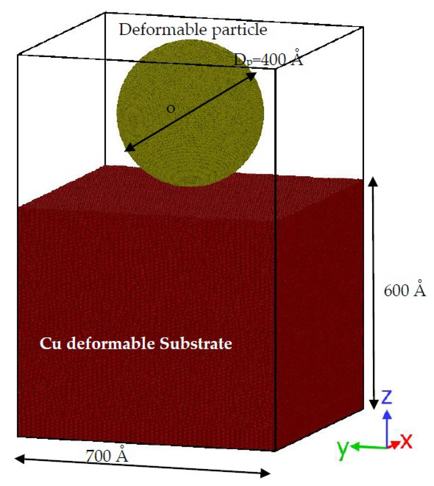
2. Computational Approach

The simulations of molecular dynamics (MD) were used to analyze the deposition behaviour of ductile nanoscale material particles in compliance with material combination and impact velocities. The large-scale atomic/molecular massively parallel simulator (LAMMPS) package [54] has been used to conduct MD simulations of nano-scale particles impaction. To understand the deformation process during particle deposition, OVITO [55], an accessible visualization tool, was used to examine the cross-section of the impact region. Figure 1 displays a diagram of the preliminary 3D simulation model for the deposition of nanoscale particles onto a Cu substrate. The analysis of the deposition characteristic of nanoscale ductile material preparation was considered in deformable spherical nano-scale Al, Ni, Cu, and Ag particles of 400 Å diameter and impact velocities of 500 to 1500 m/s. The particle material consists of around 2,051,820 atoms. The substrate is aligned in the [1 0 0], [0 1 0] and [0 0 1] for x-, y- and z- crystallographic direction, respectively. The substrate material consists of a face-centered cubic (FCC), with 3.61 Å lattice constant. The Cu substrate dimensions along an x-, y-, and z-direction are 700 Å × 700 Å × 600 Å. The initial distance from the particles to the substrate surface is 20 Å. The x-, y-, and z-directions are subjected to periodic boundary conditions (p p p). The substrate consists of the fixed boundary layer (700 Å × 700 Å × 50 Å), the thermostat layer (700 Å × 700 Å × 100 Å) and dynamic layer (700 Å × 700 Å × 500 Å. The phase time is 1.0 fs.
In the setup of the first simulation, the thermal region maintained at 273 K was set into contact with the system via thermostat layer. This thermally linked area (the “heat sink”) was the channel for the heat produced by the impact of the system to be expelled out of the system. The movement equations of the atoms in the thermal layer were incorporated into the Nosé–Hoover thermostat of NVT ensemble [56], while the motion equations of dynamic layer and particle were incorporated into the NVE ensemble. In the NVT ensemble, a particle-substrate system was equilibrated for 20 ps. For the second simulation setting in the NVE ensemble also for dynamic layer, an MD simulation was performed that removes the heat coupling and processes the whole system as thermally isolated. The particle spray velocity ranges from 500 m/s to 1500 m/s in the perpendicular direction to the substrate surface to preserve adhesion and prevent erosive wear behaviour [57,58,59]. The molecular dynamics simulation time for CGDS is 20 ps. Note, the CGDS process will not last for 20 ps, this simulation time was only allowed to ensure that the effect is completely applied is the CGDS time set. The model sizes and parameters of the simulation are presented in Table 1. The particle/substrate atomic interactions are represented by the Zhou et al. [60] embedded-atom method (EAM) potential as shown in Equation (1).
P E n = γ α ( m n ρ β ( R m n ) ) + 0.5 m n ϑ α β ( R m n )  
where P E n of atom m is the potential energy, R m n is a distance from atoms n to m , the pair-wise potential function is denoted by ϑ α β , ρ β is the influence of atom type β to the electron-charge density at atomic n , and γ is the embedding function that denotes the energy needed to position type α of atom m in the electron cloud. For the analysis of the atomic stress, the stress tensor’s six components are calculated based on the atomic viral stress spatial and temporal averages, as shown in Equation (2).
σ a b = ( m v a v b + 0.5 n = 1 n p ( R 1 a F 1 b + R 2 a F 2 b ) )  
where σ a b is the components of the atomic stress arranged in a ,   b ( x , y   o r   z ) ,   m v a v b is the kinetic energy input and 0.5 n = 1 n p ( R 1 a F 1 b + R 2 a F 2 b ) is the pair-wise energy input that is connected with the nearby atoms from n = 1 to n p . The von Mises stress is mostly used to research plastic deformation in the CGDS process, as deduced in Equation (3).
σ v a ( i ) = ( 0.5 ( σ a a ( i ) σ b b ( i ) ) 2 + 6 σ a b 2 ( i ) ) 0.5
where σ v a ( i ) is the atom von Mises stress i , σ a b ( i ) ) is the component of atomic stress tensor arrange in a, b (x, y, or z). The atomicity is computed from each MD timestep using the interatomic interaction, atomic velocity and atomic distance; Equation (3) is an abridged representation, the measurement method information is in [61,62]. The common neighbor analysis (CNA) [63,64] is implemented to classify atoms into various local lattice frameworks for atomization (fcc- face-centered cubic, bcc- body-centered cubic, hcp- hexagonal close-packed, etc.), and jetting zone atoms (without lattice structures). Additionally, the dislocation extraction algorithm (DXA) [65] is used to classify the dislocation arrangement in crystals and generate dislocation segments.

3. Results and Discussion

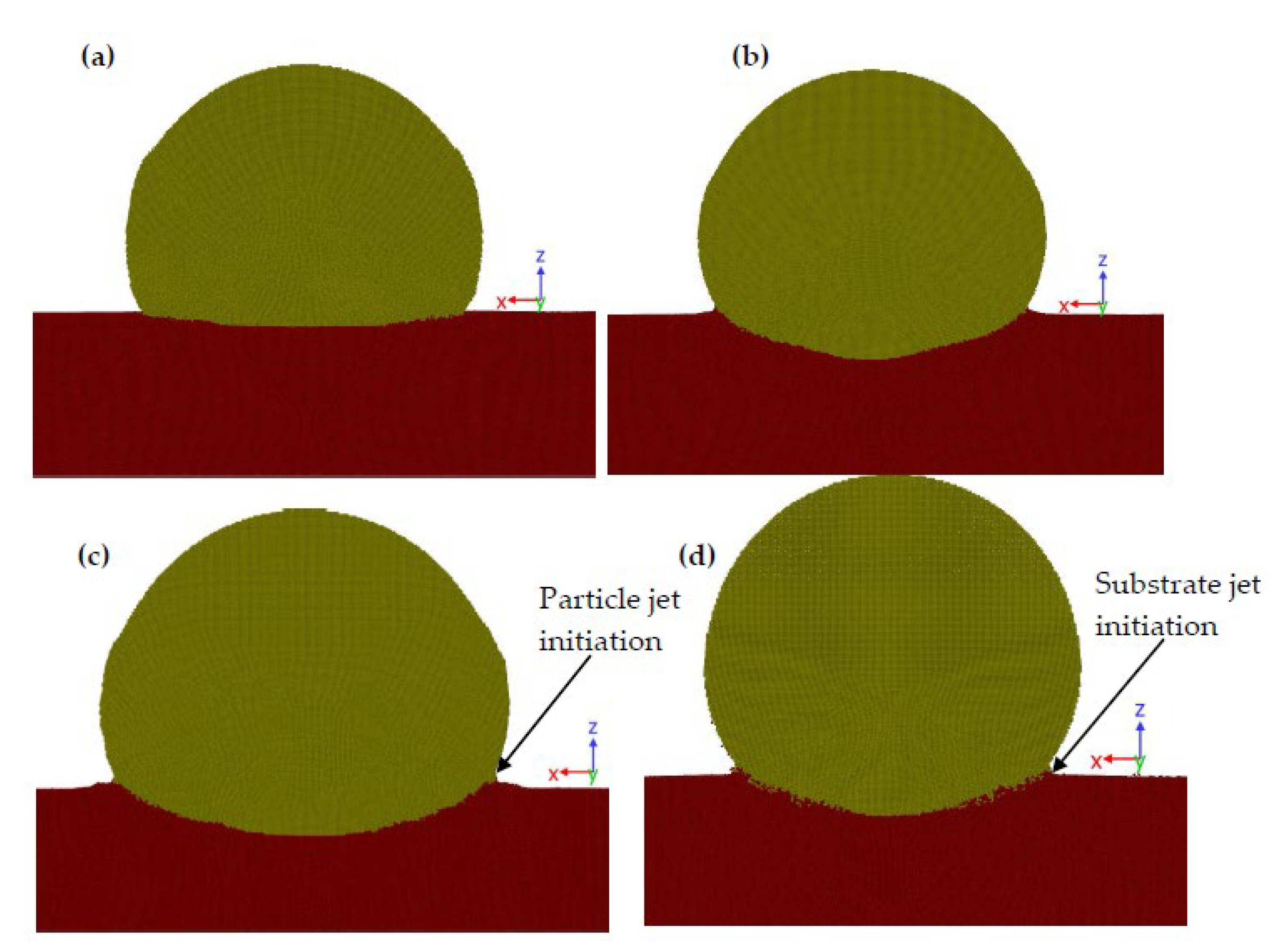
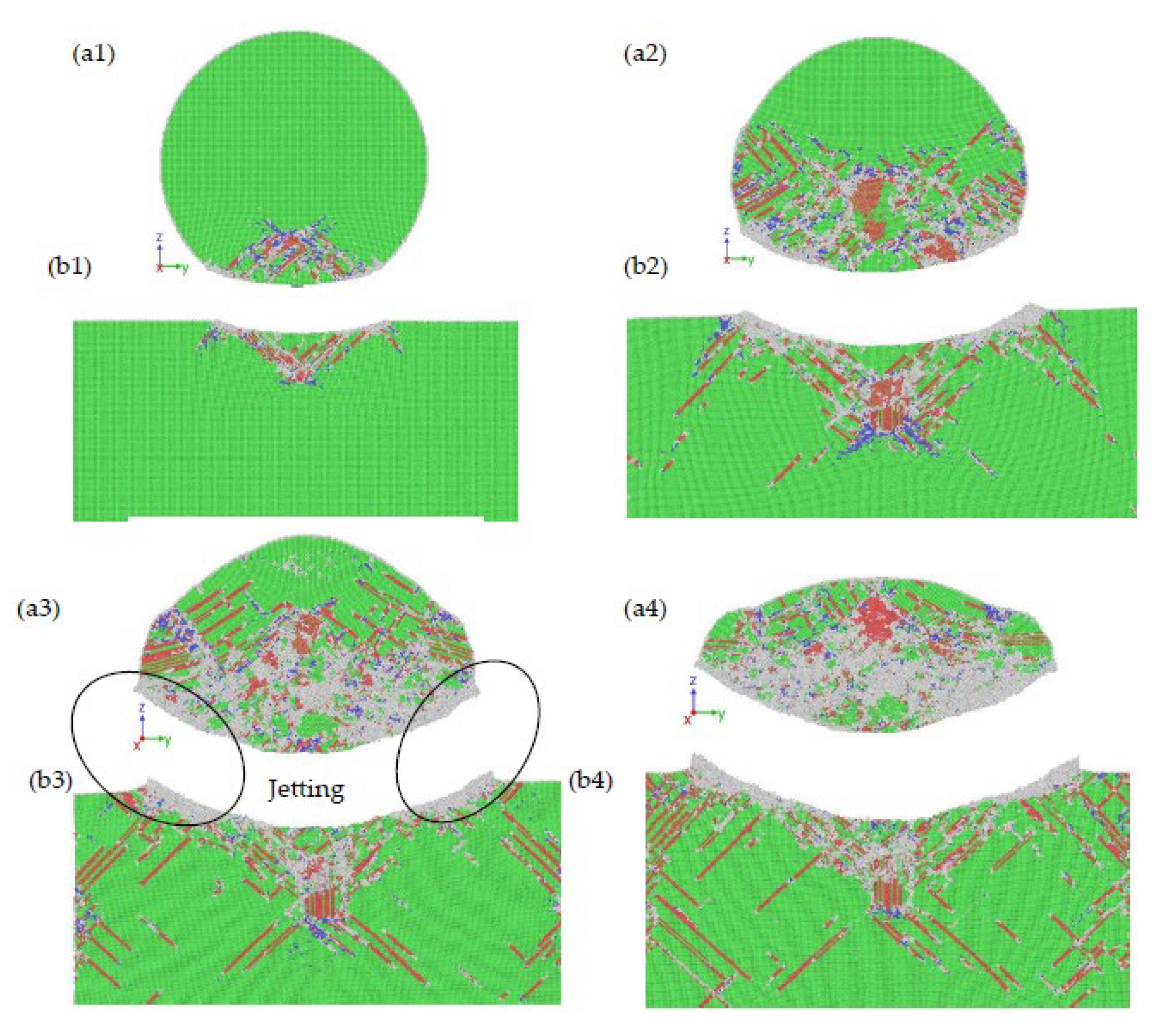
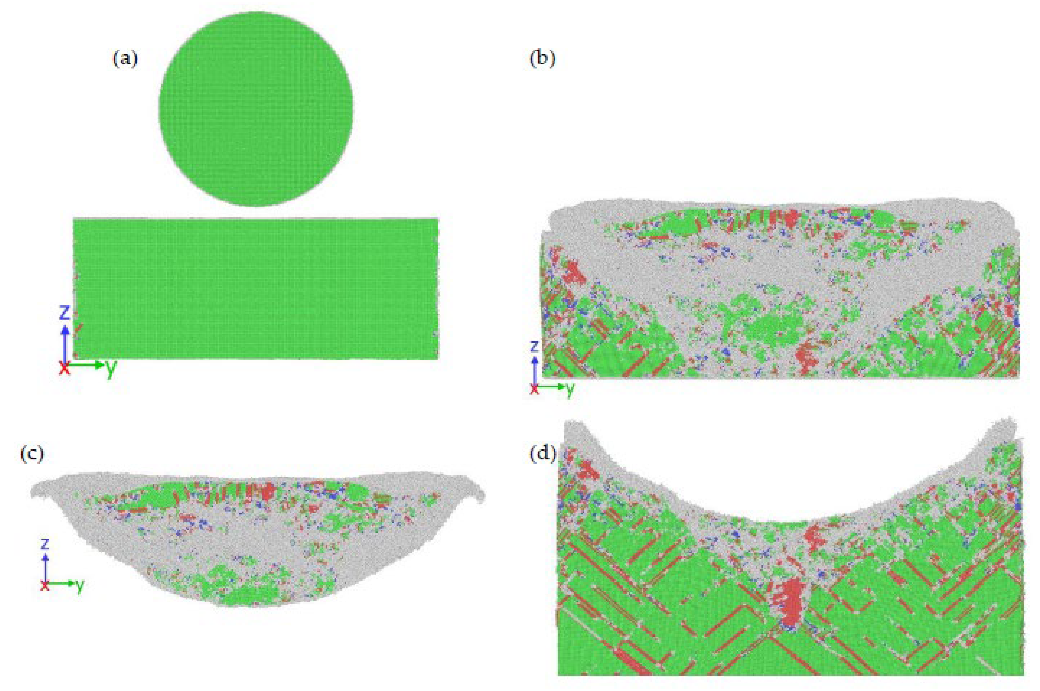
3.1. Atomic Structure Evolution and Material Jet Initiation

Continuum models [34] recently proposed that jetting initiation in the course of the impact of single-particle is due to the pressure waves propagating and interacting with the particle/substrate interfacial region. The formation of a jet is due to the ejection of particulate material at the edge of the bonded interfacial region which is attributed to the creation of a tensile area resulting in a process of “spall” because of the tensile pressures produced by the particle/substrate edge. The interaction of the pressure wave at the particle/substrate periphery is suggested as a significant factor for jetting initiation instead of the shear localization process, and adiabatic shear instability has been suggested as a consequence, instead of the cause, of jetting. This phenomenon, powered by hydrodynamic pressures, is similar to that seen in fluid–particle impacts (Kelvin–Helmholtz instability); jetting is experiential when the velocity of the shock wave surpasses the velocity at the particle/substrate peripheries [66,67].
Therefore, the molecular dynamics simulations are conducted to analyze the function of the components of pressure wave generation and the creation of thermal boost-up region leading to adiabatic shear instability at the interface. The temperature evolution in the interfacial zone is contrasted with the impacts of various ductile materials such as Al/Cu, Ni/Cu, Cu/Cu, and Ag/Cu at 1000 m/s. The impact of an Ag particle creates the highest pressure wave propagating into the substrate and particle from the point of impact till around 15 ps, resulting in deformation of particles and substrate as well as heat generation followed by that of Cu, Ni, and Al impact, respectively, as shown in Figure 2. Comparative snapshots of jet-forming microstructure are shown in Figure 3 for the material combination.
In Figure 4, the evolution of pressure wave interaction at particle/substrate interfacial region at 1000 m/s and 273 K in the thin cross-section through the middle of the particle is shown at 10 ps. The delineation levels are selected to provide a good visual image of the interactions between the compressive shockwave and the particle/substrate periphery if any, and its position in jet initiation. The effect produces a compressive wave of approximately 2.8 GPa for the Ag particle impact at the impact speed of 1000 m/s in the impacted interface. This compressive wave moves via the particle at the rear as well as through the interface of particle/substrate region, in conflict with particle/substrate lateral shear motion, as Figure 4 indicates. The shock wave reaches the periphery of the particle/substrate edge, in this case, leading to the external materials flow and causing the particle and substrate to form a jet. This jet initiation phenomenon resulted in the substrate and particle pressure drop and discharge at the interfacial zone as Figure 2 shows. In this context, previous research at the continuum level typically characterizes the mechanism of jetting associate with a particle only, while the MD simulations also display the position of the substrate in jet formation. In comparison, the Al/Cu, Ni/Cu, Cu/Cu, and Ag/Cu impact produces a maximum pressure wave of 1.63 GPa, 1.68 GPa, 2.28 GPa, and 2.82 GPa, respectively. The pressure wave evolution in Al/Cu impact does not seem to interfere with the interface boundary of the particle/substrate periphery and a jet initiation for Al/Cu impact is not observed, as displayed in Figure 4a.
While the position of the pressure wave interactions at jet initiation build-up is important, the full picture of this phenomenon should be given to further variable trends such as temperatures and von Mises stresses (flow stress) evolution. The progressive temperatures evolution at 1000 m/s impact velocity of single-particle effect for different material combinations are illustrated in Figure 5 for 20 ps simulation time. The Ag/Cu impact produces the highest interface temperatures in the particle/substrate impacting region. The temperatures in these regions are about 460 K, which is lower than the melting temperature of Ag estimated by the force field (interatomic potential). The existence and position of these elevated temperatures zones make the flow of material at the periphery of the particle/substrate interface easier. Figure 5 shows that while the high-temperature values may occur, leading to substantial material softening, the temperature gradually decreasing after reaching the peak while the outward material flow continues. The temperature spike is instigated by the emergence of the plastic deformation wave at the periphery of the particle/substrate interface, and the emergence of the waves causes the material to flow outward and the temperature drops at the interfacial edge. The corresponding flow stress evolution (von Mises) is also displayed in Figure 6 with respect to time. For clarity of visualization, atoms with the non-fcc structure that are defined in the adaptive common neighbor algorithm (CAN) are shown. At the peripheries of the contact zone of particle/substrate interface, the maximum value of von Mises stress value for the particle impact is approximately 28.2 GPa, which can be related to imminent yield and propagated rapidly within the particle with progressive flattening. In the regions near the boundary, material flow stress also increases, radially reduces to the middle of the particle interface, and falls after reaching a peak, as shown in Figure 6.
The Radial Distribution Function (RDF) is also available for testing the atomic crystallinity and providing an average, global insight of the structure of atoms in the required region of importance. The measured radial distribution function for the jetting region strongly demonstrates an amorphous structure of various combinations of materials as shown in Figure 7 after 20 ps in all particles. The RDFs results in the particle jet zone are nearly identical as shown in Figure 7. The first peak was observed at 2.50 Å, which is the closest neighbor range between the impacted pair atoms. After the initial peak comes a weak peak at approximately 3.5 Å, which is nearly close to both the gaps between pairs of atoms. Then, at 4.40 Å, 5.32 Å, and 5.75 Å, are the next three separate peaks, suggesting the development of an amorphous structure, in agreement with earlier experimental findings [68,69,70].

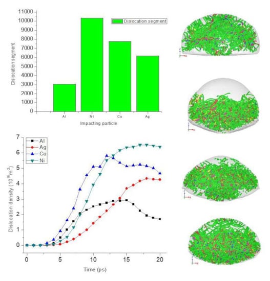
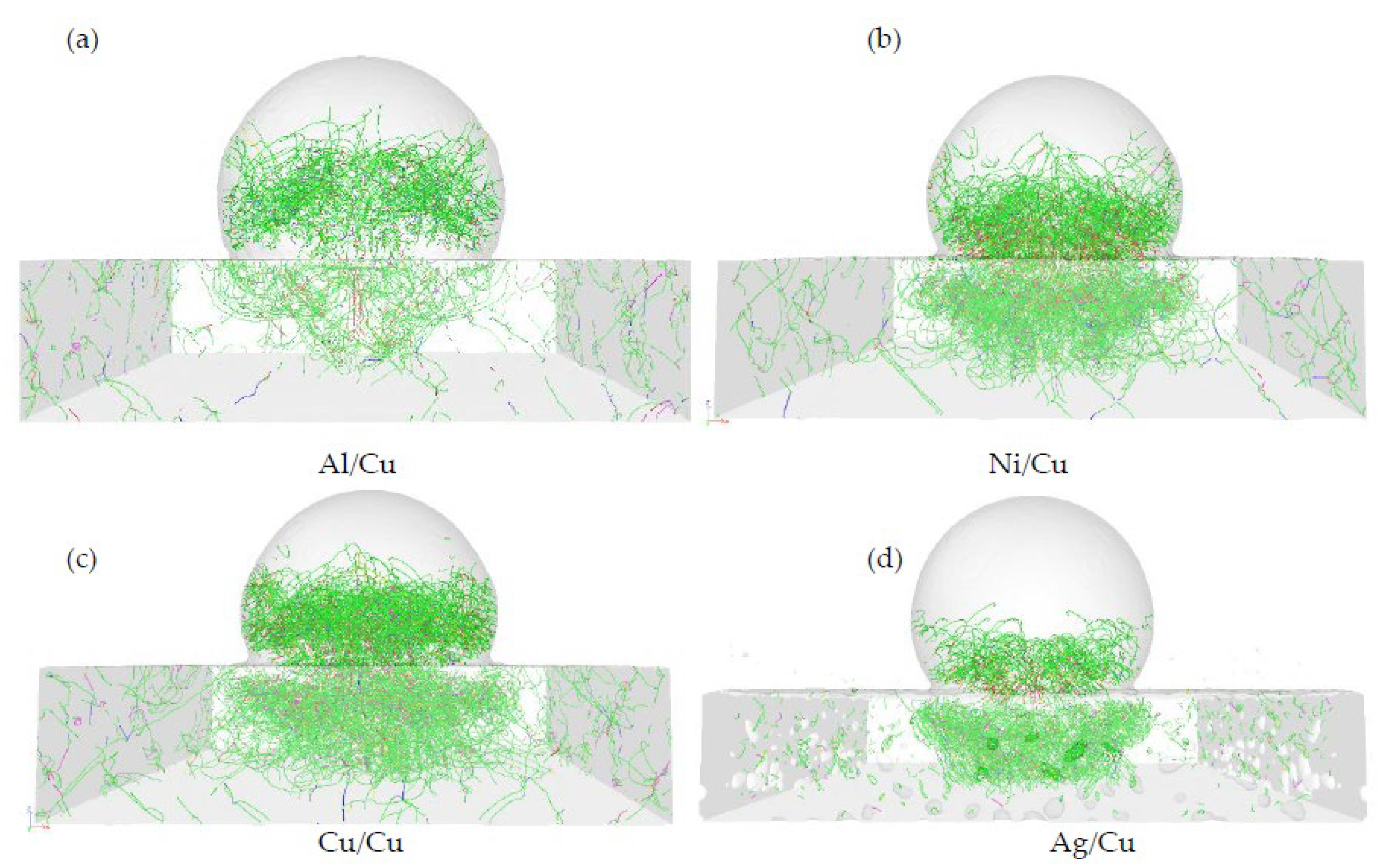
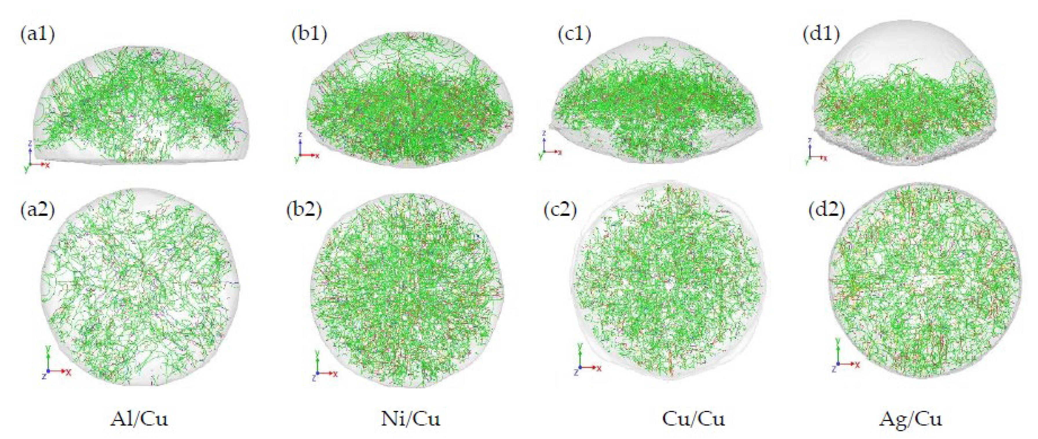
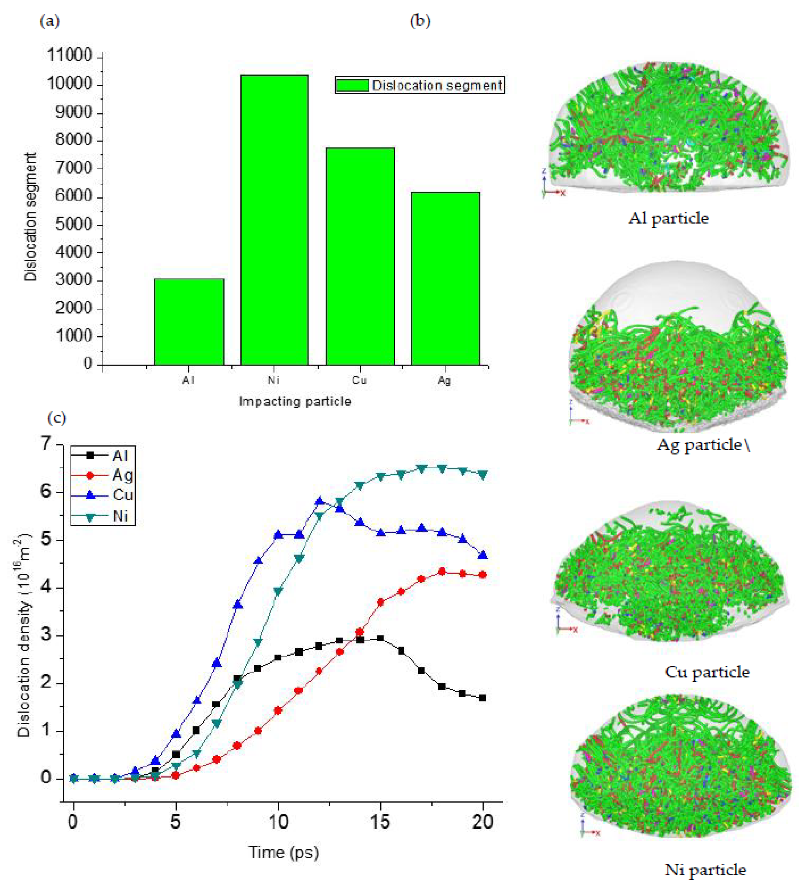
3.2. Material Dislocation Plasticity

As is evident in Figure 8, plasticity of material dislocation at 10 ps on the circular side of its flattened base for which heterogeneous nucleation of Shockley with Burgers vector 1/6 〈1 1 2〉 leading partial dislocation segments was observed. In the particle/substrate interfacial zone, the evolution of the microstructure corresponds to various ductile materials, where the perfect dislocation, the stair dislocations, and partial dislocations in Shockley is colored in blue, purple, and green, respectively. The yellow and sky-blue dislocation segment corresponds to the Hirth and Frank type, respectively. In the first step, Shockley partial dislocations emerge successively from the particle/substrate contact surface and disperse within the substrate and the particle. Then, with the growth of plastic deformation, the Shockley partial dislocations at 10 ps cover the particle/substrate interfacial zone. These imperfect dislocations normally act as carriers of energy for the face-centered cubic (fcc) system’s intrinsic stacking faults [71]. With cold gas dynamic spray proceeding, the Burgers vector of 1/6 〈1 1 2〉 with Shockley partial dislocations intersect and change to be Burgers vector of 1/6 〈1 1 0〉 with the Stair-rod dislocations. Within the particle/substrate contact zone, the Burgers vector of 1/2 〈1 1 0〉 appears, which is the perfect dislocation. The atoms on the circular edge of the particle flattened base steadily grow with the unstructured form of the atomic crystal. Moreover, dislocations are likely to move to the middle of the Al particle, to the edge and bottom of the Ni and Cu particle, as well as to the bottom of the Ag particle, as seen in Figure 8a–d.
In all particles, during the particle impact at 1000 m/s, several dislocation segments emerge, which are due to severe plastic deformations as demonstrated in Figure 9. Additionally, on the substrate surface, the lower atoms at the base of the particles form a metal-to-metal coating region. Owing to the inadequate slip on the middle part of the Al particle, there is a significant surface protrusion in the final Al particle designated at the x–z plane, which forms a “peak-shaped” coating configuration and the ultimate particle shape is rectangular in the x–z region. For the Ni particle, the absolute form of the particle on the x–z plane is comparatively flat because of the adequate slip along the direction of material flow, and the final structure in x–z plane is like a mushroom. For the Cu and Ag particle, the final structure in the x–z plane is pyramidal and hemispheric.
Figure 10 demonstrates the time-dependence of the dislocation density for different particles at 1000 m/s impact velocity. The Ni particle plastic deformation rate is the maximum following the dislocation segment evolution as shown in Figure 10a, followed by the Cu particle, then the Ag particle, and the Al particle is the lowest. In Figure 10c, the evolution of the particle dislocation density during cold gas dynamic spraying is shown between 0 ps and 20 ps. In all the different material combinations, the displacement density of all particles is near zero at the early stage of cold gas dynamic spray between 0 ps and 2 ps because no major plastic deformation exists. Then the dislocation density within various material particles from 2–20 ps increases steadily at different rates until it reaches the equilibrium after impact. The dislocation growth rate in Ni particles is about 55.4%, 33.8%, and 10.7% higher than in Al, Ag and Cu particles, respectively. In Al particle atoms, the kinetic energy is used mainly to transfer atoms along with the position of longitudinal intrinsic stacking faults. However, in Ag particles, a portion of the particle atoms’ kinetic energy is utilized in the particle/substrate atomic motion, while the particle/substrate interaction, creating several dislocations by consuming the kinetic energy that remains. The particle atoms’ kinetic energy of the Ni and Cu particle is primarily absorbed by the intense interaction between the intrinsic stacking faults in the lower part of the particle, which increases the dislocation density rapidly. Figure 10b shows the dislocation segments distribution in the Al, Ni, Cu and Ag particles at 20 ps. The dislocation density increases to the value of 2.9 × 10 16   m 2 , 4.3 × 10 16   m 2 ,   5.8 × 10 16   m 2 , and 6.5 × 10 16   m 2 for Al, Ag, Cu, and Ni particles, respectively, then decreases slightly. The extreme plastic deformation at the interface of the substrate and material particle contributes to the creation of a jet region around the interface region of particle/substrate.

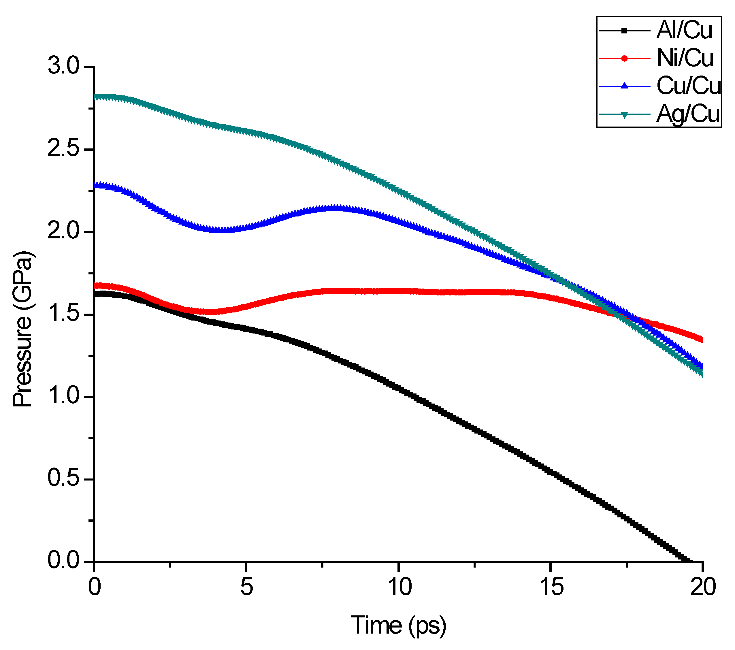
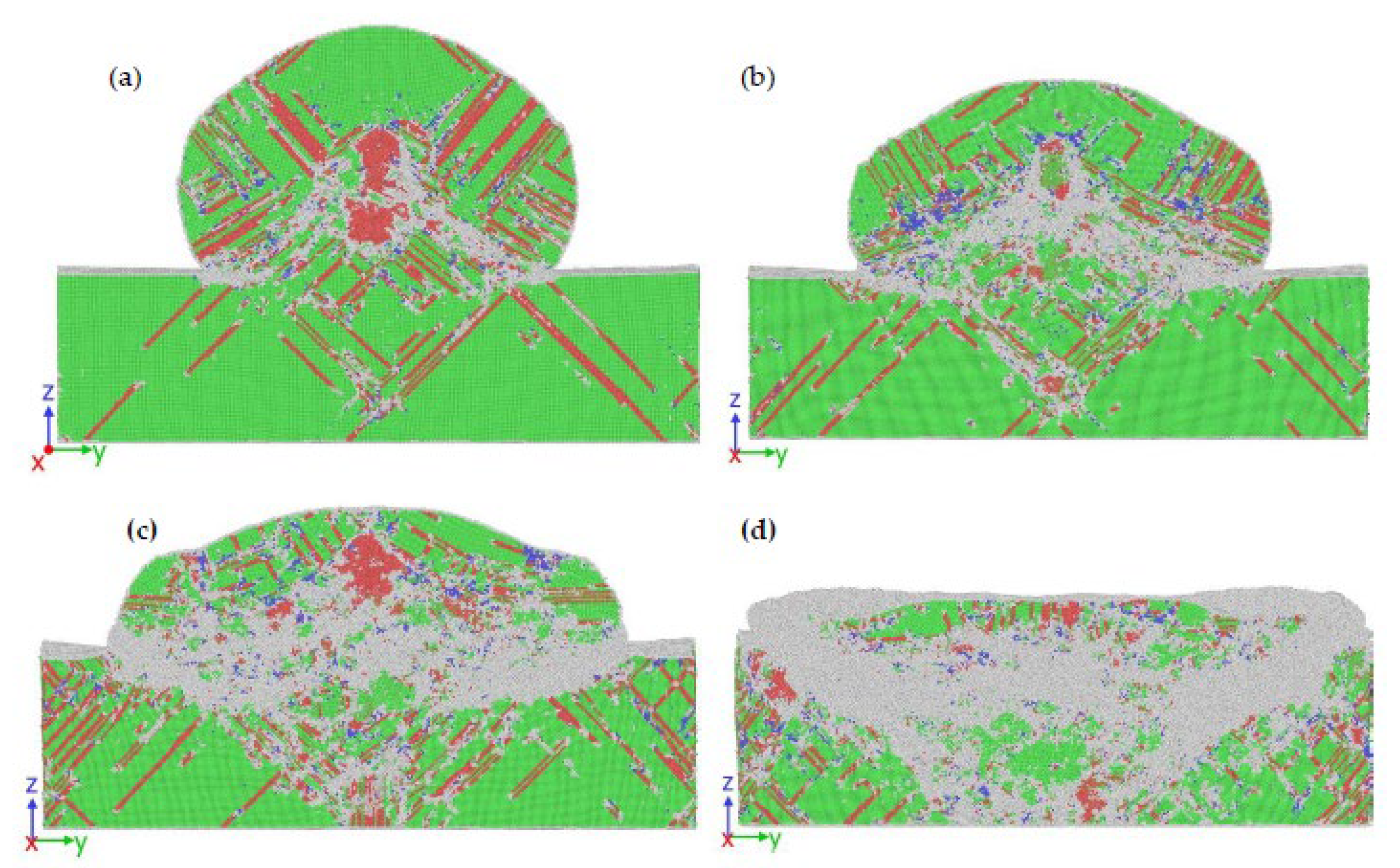
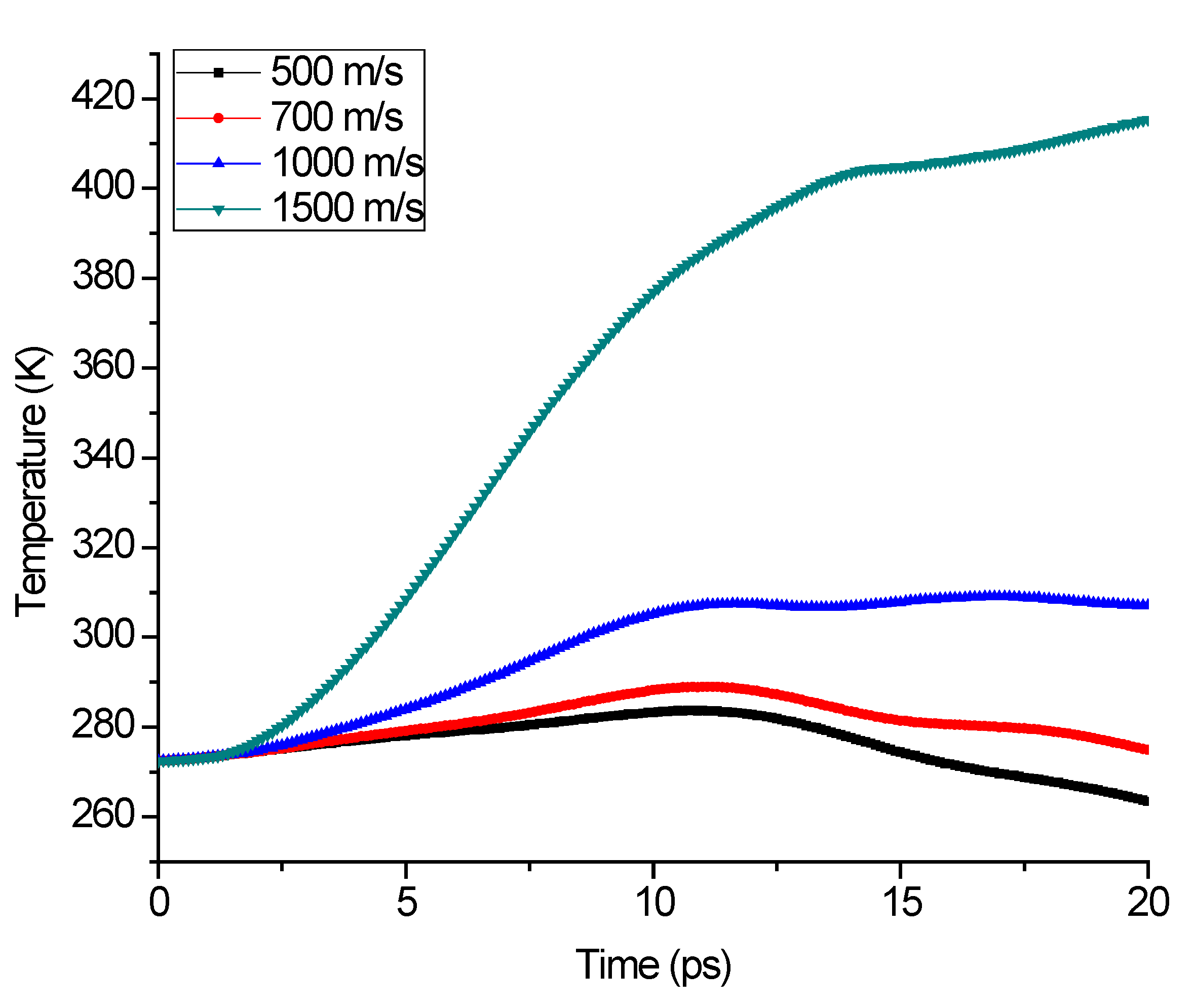
3.3. Particle Impact Velocity Effect on Microstructure Evolution

The microstructural snapshot of the full Ni splat region coated at different times on the Cu substrate for an impact speed of 1000 m/s is shown in Figure 11a–c. The local atomic structure is colored based on common neighbor analysis (CNA) approach [63,64]: FCC (green), HCP (red), BCC (blue) and grey (atoms without crystalline structure). The circles designated the jet formation at the periphery as the atoms flow upward from the substrate. The snapshots presenting the particle and substrate separately of the illustrative atoms. The material jet initiation at the periphery is often correlated with the outward flow of atoms as shown by the circles from the substrate.
During MD simulations of single material impact for a particle impact velocity of 500 m/s, 700 m/s, 1000 m/s, and 1500 m/s, the microstructure evolution and recrystallization behavior are also investigated. The recrystallization potential varies at impact speeds as establish in the cold dynamic gas sprayed splats created during 20 ps, which shows the local atomic structure at 273 K in Figure 12. With a particle velocity of the impact of 500 m/s, recrystallized structures are very few, as indicated in Figure 12a, in contrast with the 1500 m/s particle impact velocity with large structural transformation as displayed in Figure 12d. The increased number of new atomic structures can be associated with the reliance of recrystallization phenomenon associated with strain energy to indicate the unique recrystallization mechanisms [69,72] involved in the molecular dynamics predicted microstructures given the extreme deformation of the atomic structure at the interface. In addition to the recrystallization in the creation of new structures, atomic structure boundary migration [73] could also play a critical position. For convenience, in this manuscript, the development of a new atomic structure is called recrystallization. Metal plastic deformation is more severe with a higher impact velocity of 1500 m/s, and therefore greater temperatures are produced during the impact time at the particle/substrate interfacial region as shown in Figure 13. Some experimental cold gas dynamic sprays have achieved a similar consensus on the recrystallization phenomenon [74,75,76]. In the past, the embedded atomic potential (EAM/alloy) [60] used in this study has shown a recrystallization of aluminum uniaxial loading, demonstrating its ability to capture the phenomenon accurately [77]. Figure 14 shows that, at the interface, some of this recrystallized atomic structure is split between particle and substrate. These findings show that recrystallization at some region at the interfacial zones will help form the metallurgical bond between the substrate and the particle.

4. Conclusions

Cold gas dynamic spray impacts on pure copper substrates of nanoscale ductile materials such as Al, Ni, Cu, and Ag are modelled using a molecular dynamic simulation (MD) system for differing material combinations, particle impact velocities, and microstructures. The post-impact behaviour is objectively studied by monitoring the distribution of the thermomechanical variable such as pressure wave, temperature, stress, dislocation density, and microstructural features such as local atomic structural transformation at the nanoscale. We studied the position and the propagation of the compressive shock wave in activating a jet at the interface of particle/substrate impact region.
The findings of the simulation show that the jetting phenomenon, as the material deforms during impact, is due to the interaction between the velocity of the shock wave at the interface of the particle/substrate interfacial zone and the velocity at the edge of particle/substrate interface. The effect produces a compressive wave of approximately 2.8 GPa for the Ag particle impact at the impact speed of 1000 m/s in the impacted zone. This compressive wave moves via the particle at the rear as well as through the interface of particle/substrate region, in conflict with particle/substrate lateral shear motion. The shock wave reaches the periphery of the particle/substrate edge, in this case, leading to the external materials flow and causing the particle and substrate to form a jet. The pressure wave evolution in Al/Cu impact does not seem to interfere with the interface boundary of the particle/substrate periphery and a jet initiation for Al/Cu impact is not observed. The impact of an Ag particle creates the highest-pressure wave propagating into the substrate and particle from the point of impact till around 15 ps, resulting in deformation of particles and substrate as well as heat generation followed by that of Cu, Ni, and Al impact, respectively.
The deformation behavior for individual impacting particles and subsequent dislocation evolution allowed us to classify the stages of deformation into three, after the impact analysis of particle/substrate impact. Firstly, plastic deformation began by the slide of dislocations and nucleation at the exterior end of the particle that is in close contact with the surface of the substrates at impact. Thereafter, with additional deformation, the analysis of the dense dislocation segment when comparing the initial and the final microstructures of the splat show dislocation network formation formed at the exterior bottom of the particles, and the upper region remains essentially undeformed. Finally, as seen in the finite element method and microscopy experiments, the upper part the particle deformed as well, causing the usual flattened splat shape. The dislocation density increases to the value of 2.9 × 10 16   m 2 , 4.3 × 10 16   m 2 ,   5.8 × 10 16   m 2 , and 6.5 × 10 16   m 2 for Al, Ag, Cu, and Ni particles, respectively. The extreme plastic deformation at the interface of the substrate and material particle contributes to the creation of a jet region around the interface region of particle/substrate. The dislocation growth rate in Ni particles is about 55.4%, 33.8%, and 10.7% higher than in Al, Ag, and Cu particles, respectively.
A contrast of the original and final microstructures of the splat shows the creation, near the interface, of “new” atomic structure, which is certified by a combination of atomic boundary mobility stress-led and recrystallization of particle/substrate mechanisms. The recrystallization potential varies with the impact velocities, the thermal evolution and the stored strain energy as seen in the CGDS splats created during 20 ps, which show the local atomic structure. Some of these new structures are established on the bond line, which facilitates close interaction and strengthens CGDS splat bond. These findings expand our awareness about the processes to reinforce cold gas dynamic sprayed deposits from a modelling perspective. CGDS also qualifies as an additive manufacturing procedure to achieve the optimal strength of the deposit (coating) by the interface nucleation of finer atomic structures and the subsequent atomic boundary strengthening.

Author Contributions

S.T.O.: Conceptualization, Methodology, Investigation, Software, Visualization, Writing-Original draft. T.-C.J.: Resources, Reviewing and Editing and Supervision. All authors have read and agreed to the published version of the manuscript.

Funding

This research received no external funding.

Acknowledgments

The authors would like to acknowledge the financial support from the University Research Committee of the University of Johannesburg and the National Research Foundation of South Africa.

Conflicts of Interest

The authors declare no conflict of interest.

References

  1. Ganesan, A.; Affi, J.; Yamada, M.; Fukumoto, M. Bonding behavior studies of cold sprayed copper coating on the PVC polymer substrate. Surf. Coat. Technol. 2012, 207, 262–269. [Google Scholar] [CrossRef]
  2. Khodabakhshi, F.; Marzbanrad, B.; Jahed, H.; Gerlich, A. Interfacial bonding mechanisms between aluminum and titanium during cold gas spraying followed by friction-stir modification. Appl. Surf. Sci. 2018, 462, 739–752. [Google Scholar] [CrossRef]
  3. Lu, J.; Zhang, H.; Chen, Y.; Zhao, X.; Guo, F.; Xiao, P. Effect of microstructure of a NiCoCrAlY coating fabricated by high-velocity air fuel on the isothermal oxidation. Corros. Sci. 2019, 159. [Google Scholar] [CrossRef]
  4. Raoelison, R.; Xie, Y.; Sapanathan, T.; Planche, M.; Kromer, R.; Costil, S.; Langlade, C. Cold gas dynamic spray technology: A comprehensive review of processing conditions for various technological developments till to date. Addit. Manuf. 2018, 19, 134–159. [Google Scholar] [CrossRef]
  5. Bagherifard, S.; Monti, S.; Zuccoli, M.V.; Riccio, M.; Kondás, J.; Guagliano, M. Cold spray deposition for additive manufacturing of freeform structural components compared to selective laser melting. Mater. Sci. Eng. A 2018, 721, 339–350. [Google Scholar] [CrossRef]
  6. Oyinbo, S.T.; Jen, T.-C. Investigation of the process parameters and restitution coefficient of ductile materials during cold gas dynamic spray (CGDS) using finite element analysis. Addit. Manuf. 2020, 31, 100986. [Google Scholar] [CrossRef]
  7. Oyinbo, S.; Jen, T.-C. A comparative review on cold gas dynamic spraying processes and technologies. Manuf. Rev. 2019, 6, 25. [Google Scholar] [CrossRef] [Green Version]
  8. Irissou, E.; Legoux, J.-G.; Ryabinin, A.N.; Jodoin, B.; Moreau, C. Review on Cold Spray Process and Technology: Part I—Intellectual Property. J. Therm. Spray Technol. 2008, 17, 495–516. [Google Scholar] [CrossRef] [Green Version]
  9. Van Steenkiste, T.; Smith, J.; Teets, R. Aluminum coatings via kinetic spray with relatively large powder particles. Surf. Coat. Technol. 2002, 154, 237–252. [Google Scholar] [CrossRef]
  10. Assadi, F.H.; Gartner, T.; Stoltenhoff, H.K. Bonding mechanism in cold gas spraying. Acta Mater. 2003, 51, 4379–4394. [Google Scholar] [CrossRef]
  11. Grujicic, M.; Zhao, C.; Tong, C.; Derosset, W.; Helfritch, D. Analysis of the impact velocity of powder particles in the cold-gas dynamic-spray process. Mater. Sci. Eng. A 2004, 368, 222–230. [Google Scholar] [CrossRef]
  12. Nasim, M.; Vo, T.; Mustafi, L.; Kim, B.; Lee, C.S.; Chu, W.-S.; Chun, D.-M. Deposition mechanism of graphene flakes directly from graphite particles in the kinetic spray process studied using molecular dynamics simulation. Comput. Mater. Sci. 2019, 169. [Google Scholar] [CrossRef]
  13. Rafaja, D.; Schucknecht, T.; Klemm, V.; Paul, A.; Berek, H. Microstructural characterisation of titanium coatings deposited using cold gas spraying on Al2O3 substrates. Surf. Coat. Technol. 2009, 203, 3206–3213. [Google Scholar] [CrossRef]
  14. Grujicic, M.; Saylor, J.; Beasley, D.; Derosset, W.; Helfritch, D. Computational analysis of the interfacial bonding between feed-powder particles and the substrate in the cold-gas dynamic-spray process. Appl. Surf. Sci. 2003, 219, 211–227. [Google Scholar] [CrossRef]
  15. Zhang, D.; Shipway, P.; McCartney, D. Cold Gas Dynamic Spraying of Aluminum: The Role of Substrate Characteristics in Deposit Formation. J. Therm. Spray Technol. 2005, 14, 109–116. [Google Scholar] [CrossRef]
  16. Kim, D.-Y.; Park, J.-J.; Lee, J.-G.; Kim, D.; Tark, S.J.; Ahn, S.; Yun, J.H.; Gwak, J.; Yoon, K.H.; Chandra, S.; et al. Cold Spray Deposition of Copper Electrodes on Silicon and Glass Substrates. J. Therm. Spray Technol. 2013, 22, 1092–1102. [Google Scholar] [CrossRef]
  17. King, P.C.; Zahiri, S.; Jahedi, M.; Friend, J. Aluminium coating of lead zirconate titanate—A study of cold spray variables. Surf. Coat. Technol. 2010, 205, 2016–2022. [Google Scholar] [CrossRef]
  18. Hussain, T.; McCartney, D.; Shipway, P. Bonding between aluminium and copper in cold spraying: Story of asymmetry. Mater. Sci. Technol. 2012, 28, 1371–1378. [Google Scholar] [CrossRef]
  19. Oyinbo, S.; Jen, T.-C. Feasibility of numerical simulation methods on the Cold Gas Dynamic Spray (CGDS) Deposition process for ductile materials. Manuf. Rev. 2020, 7, 24. [Google Scholar] [CrossRef]
  20. Seo, D.; Sayar, M.; Ogawa, K. SiO2 and MoSi2 formation on Inconel 625 surface via SiC coating deposited by cold spray. Surf. Coat. Technol. 2012, 206, 2851–2858. [Google Scholar] [CrossRef]
  21. Burlacov, I.; Jirkovský, J.; Kavan, L.; Ballhorn, R.; Heimann, R.B. Cold gas dynamic spraying (CGDS) of TiO2 (anatase) powders onto poly(sulfone) substrates: Microstructural characterisation and photocatalytic efficiency. J. Photochem. Photobiol. A Chem. 2007, 187, 285–292. [Google Scholar] [CrossRef]
  22. Amirthan, G.; Yamada, M.; Fukumoto, M. Cold Spray Coating Deposition Mechanism on the Thermoplastic and Thermosetting Polymer Substrates. J. Therm. Spray Technol. 2013, 22, 1275–1282. [Google Scholar] [CrossRef]
  23. Lupoi, R.; O’Neill, W. Deposition of metallic coatings on polymer surfaces using cold spray. Surf. Coat. Technol. 2010, 205, 2167–2173. [Google Scholar] [CrossRef] [Green Version]
  24. Zhou, X.; Chen, A.; Liu, J.; Wu, X.; Li, Y. Preparation of metallic coatings on polymer matrix composites by cold spray. Surf. Coat. Technol. 2011, 206, 132–136. [Google Scholar] [CrossRef]
  25. King, P.C.; Poole, A.J.; Horne, S.; De Nys, R.; Gulizia, S.; Jahedi, M.Z. Embedment of copper particles into polymers by cold spray. Surf. Coat. Technol. 2013, 216, 60–67. [Google Scholar] [CrossRef]
  26. Alhulaifi, A.S.; Buck, G.A.; Arbegast, W.J. Numerical and Experimental Investigation of Cold Spray Gas Dynamic Effects for Polymer Coating. J. Therm. Spray Technol. 2012, 21, 852–862. [Google Scholar] [CrossRef]
  27. Robitaille, F.; Yandouzi, M.; Hind, S.; Jodoin, B. Metallic coating of aerospace carbon/epoxy composites by the pulsed gas dynamic spraying process. Surf. Coat. Technol. 2009, 203, 2954–2960. [Google Scholar] [CrossRef]
  28. Champagne, V.K.; Helfritch, D.; Leyman, P.; Grendahl, S.; Klotz, B. Interface Material Mixing Formed by the Deposition of Copper on Aluminum by Means of the Cold Spray Process. J. Therm. Spray Technol. 2005, 14, 330–334. [Google Scholar] [CrossRef]
  29. Ko, K.; Choi, J.; Lee, H. Intermixing and interfacial morphology of cold-sprayed Al coatings on steel. Mater. Lett. 2014, 136, 45–47. [Google Scholar] [CrossRef]
  30. Yin, S.; Cavaliere, P.; Aldwell, B.; Jenkins, R.; Liao, H.; Li, W.; Lupoi, R. Cold spray additive manufacturing and repair: Fundamentals and applications. Addit. Manuf. 2018, 21, 628–650. [Google Scholar] [CrossRef]
  31. Moridi, A.; Gangaraj, S.; Guagliano, M.; Dao, M. Cold spray coating: Review of material systems and future perspectives. Surf. Eng. 2014, 30, 369–395. [Google Scholar] [CrossRef]
  32. Xie, Y.; Yin, S.; Chen, C.; Planche, M.-P.; Liao, H.; Lupoi, R. New insights into the coating/substrate interfacial bonding mechanism in cold spray. Scr. Mater. 2016, 125, 1–4. [Google Scholar] [CrossRef]
  33. Grujicic, M.; Zhao, C.; Derosset, W.; Helfritch, D. Adiabatic shear instability based mechanism for particles/substrate bonding in the cold-gas dynamic-spray process. Mater. Des. 2004, 25, 681–688. [Google Scholar] [CrossRef]
  34. Hassani-Gangaraj, M.; Veysset, D.; Champagne, V.K.; Nelson, K.A.; Schuh, C.A. Adiabatic shear instability is not necessary for adhesion in cold spray. Acta Mater. 2018, 158, 430–439. [Google Scholar] [CrossRef]
  35. Murr, L.E.; Esquivel, E.V. Observations of common microstructural issues associated with dynamic deformation phenomena: Twins, microbands, grain size effects, shear bands, and dynamic recrystallization. J. Mater. Sci. 2004, 39, 1153–1168. [Google Scholar] [CrossRef]
  36. Rahmati, S.; Zúñiga, A.; Jodoin, B.; Veiga, R. Deformation of copper particles upon impact: A molecular dynamics study of cold spray. Comput. Mater. Sci. 2020, 171, 109219. [Google Scholar] [CrossRef]
  37. Oyinbo, S.; Jen, T.-C.; Aasa, S.A.; Abegunde, O.; Zhu, Y. Development of palladium nanoparticles deposition on a copper substrate using a molecular dynamic (MD) simulation: A cold gas dynamic spray process. Manuf. Rev. 2020, 7, 29. [Google Scholar] [CrossRef]
  38. Bae, G.; Kumar, S.; Yoon, S.; Kang, K.; Na, H.; Kim, H.-J.; Lee, C. Bonding features and associated mechanisms in kinetic sprayed titanium coatings. Acta Mater. 2009, 57, 5654–5666. [Google Scholar] [CrossRef]
  39. Oyinbo, S.T.; Jen, T.-C.; Zhu, Y.; Ajiboye, J.S.; Ismail, S.O. Atomistic simulations of interfacial deformation and bonding mechanism of Pd-Cu composite metal membrane using cold gas dynamic spray process. Vacuum 2020, 182, 109779. [Google Scholar] [CrossRef]
  40. Wang, Q.; Birbilis, N.; Zhang, M.-X. Interfacial structure between particles in an aluminum deposit produced by cold spray. Mater. Lett. 2011, 65, 1576–1578. [Google Scholar] [CrossRef]
  41. Guetta, S.; Berger, M.-H.; Borit, F.; Guipont, V.; Jeandin, M.; Boustie, M.; Ichikawa, Y.; Sakaguchi, K.; Ogawa, K. Influence of Particle Velocity on Adhesion of Cold-Sprayed Splats. J. Therm. Spray Technol. 2009, 18, 331–342. [Google Scholar] [CrossRef]
  42. Henao, J.; Concustell, A.; Dosta, S.; Bolelli, G.; Cano, I.; Lusvarghi, L.; Guilemany, J. Deposition mechanisms of metallic glass particles by Cold Gas Spraying. Acta Mater. 2017, 125, 327–339. [Google Scholar] [CrossRef]
  43. Oyinbo, S.T.; Jen, T.-C. Molecular dynamics investigation of temperature effect and surface configurations on multiple impacts plastic deformation in a palladium-copper composite metal membrane (CMM): A cold gas dynamic spray (CGDS) process. Comput. Mater. Sci. 2020, 185, 109968. [Google Scholar] [CrossRef]
  44. Fukumoto, M.; Mashiko, M.; Yamada, M.; Yamaguchi, E. Deposition Behavior of Copper Fine Particles onto Flat Substrate Surface in Cold Spraying. J. Therm. Spray Technol. 2009, 19, 89–94. [Google Scholar] [CrossRef]
  45. Zhao, P.; Zhang, Q.; Guo, Y.; Liu, H.; Deng, Z. Atomic simulation of crystal orientation effect on coating surface generation mechanisms in cold spray. Comput. Mater. Sci. 2020, 184, 109859. [Google Scholar] [CrossRef]
  46. Salehinia, I.; Lawrence, S.K.; Bahr, D. The effect of crystal orientation on the stochastic behavior of dislocation nucleation and multiplication during nanoindentation. Acta Mater. 2013, 61, 1421–1431. [Google Scholar] [CrossRef]
  47. Basu, S.; Wang, Z.; Saldana, C. Anomalous evolution of microstructure and crystallographic texture during indentation. Acta Mater. 2016, 105, 25–34. [Google Scholar] [CrossRef]
  48. Oyinbo, S.; Jen, T.-C. A Molecular Dynamics Investigation of the Temperature Effect on the Mechanical Properties of Selected Thin Films for Hydrogen Separation. Membranes 2020, 10, 241. [Google Scholar] [CrossRef]
  49. Hassani-Gangaraj, M.; Veysset, D.; Nelson, K.A.; Schuh, C.A. In-situ observations of single micro-particle impact bonding. Scr. Mater. 2018, 145, 9–13. [Google Scholar] [CrossRef]
  50. King, P.C.; Zahiri, S.H.; Jahedi, M. Microstructural Refinement within a Cold-Sprayed Copper Particle. Met. Mater. Trans. A 2009, 40, 2115–2123. [Google Scholar] [CrossRef]
  51. Irissou, E.; Legoux, J.-G.; Arsenault, B.; Moreau, C. Investigation of Al-Al2O3 Cold Spray Coating Formation and Properties. J. Therm. Spray Technol. 2007, 16, 661–668. [Google Scholar] [CrossRef]
  52. King, P.C.; Busch, C.; Kittel-Sherri, T.; Jahedi, M.; Gulizia, S. Interface melding in cold spray titanium particle impact. Surf. Coat. Technol. 2014, 239, 191–199. [Google Scholar] [CrossRef]
  53. Schöner, C.; Pöschel, T. Orientation-dependent properties of nanoparticle impact. Phys. Rev. E 2018, 98, 022902. [Google Scholar] [CrossRef] [PubMed] [Green Version]
  54. Plimpton, S. Fast Parallel Algorithms for Short-Range Molecular Dynamics. J. Comput. Phys. 1995, 117, 1–19. [Google Scholar] [CrossRef] [Green Version]
  55. Stukowski, A. Visualization and analysis of atomistic simulation data with OVITO–the Open Visualization Tool. Model. Simul. Mater. Sci. Eng. 2009, 18. [Google Scholar] [CrossRef]
  56. Braga, C.; Travis, K.P. A configurational temperature Nosé-Hoover thermostat. J. Chem. Phys. 2005, 123, 134101. [Google Scholar] [CrossRef]
  57. Hassani-Gangaraj, M.; Veysset, D.; Champagne, V.K.; Nelson, K.A.; Schuh, C.A. Response to Comment on Adiabatic shear instability is not necessary for adhesion in cold spray. Scr. Mater. 2019, 162, 515–519. [Google Scholar] [CrossRef]
  58. Li, W.-Y.; Gao, W. Some aspects on 3D numerical modeling of high velocity impact of particles in cold spraying by explicit finite element analysis. Appl. Surf. Sci. 2009, 255, 7878–7892. [Google Scholar] [CrossRef]
  59. Ghelichi, R.; Bagherifard, S.; Guagliano, M.; Verani, M. Numerical simulation of cold spray coating. Surf. Coat. Technol. 2011, 205, 5294–5301. [Google Scholar] [CrossRef]
  60. Zhou, X.W.; Johnson, R.A.; Wadley, H.N.G. Misfit-energy-increasing dislocations in vapor-deposited CoFe/NiFe multilayers. Phys. Rev. B 2004, 69, 1–10. [Google Scholar] [CrossRef] [Green Version]
  61. Guo, Y.-B.; Xu, T.; Li, M. Generalized type III internal stress from interfaces, triple junctions and other microstructural components in nanocrystalline materials. Acta Mater. 2013, 61, 4974–4983. [Google Scholar] [CrossRef]
  62. Guo, Y.-B.; Xu, T.; Li, M. Hierarchical dislocation nucleation controlled by internal stress in nanocrystalline copper. Appl. Phys. Lett. 2013, 102, 241910. [Google Scholar] [CrossRef]
  63. Faken, D.; Jónsson, H. Systematic analysis of local atomic structure combined with 3D computer graphics. Comput. Mater. Sci. 1994, 2, 279–286. [Google Scholar] [CrossRef]
  64. Honeycutt, J.D.; Andersen, H.C. Molecular dynamics study of melting and freezing of small Lennard-Jones clusters. J. Phys. Chem. 1987, 91, 4950–4963. [Google Scholar] [CrossRef]
  65. Stukowski, A.; Bulatov, V.V.; Arsenlis, A. Automated identification and indexing of dislocations in crystal interfaces. Model. Simul. Mater. Sci. Eng. 2012, 20. [Google Scholar] [CrossRef]
  66. Dear, J.P.; Field, J.E. High-speed photography of surface geometry effects in liquid/solid impact. J. Appl. Phys. 1988, 63, 1015–1021. [Google Scholar] [CrossRef]
  67. Field, J.E.; Dear, J.P.; Ogren, J.E. The effects of target compliance on liquid drop impact. J. Appl. Phys. 1989, 65, 533–540. [Google Scholar] [CrossRef]
  68. Li, W.Y.; Yin, S.; Wang, X.-F. Numerical investigations of the effect of oblique impact on particle deformation in cold spraying by the SPH method. Appl. Surf. Sci. 2010, 256, 3725–3734. [Google Scholar] [CrossRef]
  69. Rokni, M.R.; Zarei-Hanzaki, A.; Abedi, H. Microstructure evolution and mechanical properties of back extruded 7075 aluminum alloy at elevated temperatures. Mater. Sci. Eng. A 2012, 532, 593–600. [Google Scholar] [CrossRef]
  70. Arabgol, Z.; Vidaller, M.V.; Assadi, H.; Gärtner, F.; Klassen, T. Influence of thermal properties and temperature of substrate on the quality of cold-sprayed deposits. Acta Mater. 2017, 127, 287–301. [Google Scholar] [CrossRef] [Green Version]
  71. Hull, D.; Bacon, D.J. Introduction to Dislocation, 4th ed.; Woburn: Butterworth, MA, USA, 2001. [Google Scholar]
  72. Rokni, M.R.; Widener, C.A.; Champagne, V. Microstructural stability of ultrafine grained cold sprayed 6061 aluminum alloy. Appl. Surf. Sci. 2014, 290, 482–489. [Google Scholar] [CrossRef]
  73. Cheng, K.; Zhang, L.; Lu, C.; Tieu, K. Coupled grain boundary motion in aluminium: The effect of structural multiplicity. Sci. Rep. 2016, 6, 25427. [Google Scholar] [CrossRef] [PubMed] [Green Version]
  74. Zou, Y.; Goldbaum, D.; Szpunar, J.A.; Yue, S. Microstructure and nanohardness of cold-sprayed coatings: Electron backscattered diffraction and nanoindentation studies. Scr. Mater. 2010, 62, 395–398. [Google Scholar] [CrossRef]
  75. Rokni, M.R.; Widener, C.; Crawford, G.; West, M. An investigation into microstructure and mechanical properties of cold sprayed 7075 Al deposition. Mater. Sci. Eng. A 2015, 625, 19–27. [Google Scholar] [CrossRef]
  76. Rokni, M.; Widener, C.; Crawford, G. Microstructural evolution of 7075 Al gas atomized powder and high-pressure cold sprayed deposition. Surf. Coat. Technol. 2014, 251, 254–263. [Google Scholar] [CrossRef]
  77. Li, X.; Wei, Y.; Yang, W.; Gao, H. Competing grain-boundary- and dislocation-mediated mechanisms in plastic strain recovery in nanocrystalline aluminum. Proc. Natl. Acad. Sci. USA 2009, 106, 16108–16113. [Google Scholar] [CrossRef] [Green Version]
Figure 1. Cold gas dynamic spray MD simulation model.
Coatings 10 01079 g001
Figure 2. The pressure wave evolution at the periphery of the particle/substrate interfacial region at 1000 m/s of single-particle impact.
Coatings 10 01079 g002
Figure 3. Splat morphologies of different material combination at 20 ps: (a) Al/Cu (showing no jet) for the whole simulation period (b) Cu/Cu, (c) Ni/Cu, and (d) Ag/Cu (b-c showing jet initiation) for 273 K.
Coatings 10 01079 g003
Figure 4. The evolution of pressure wave interaction at particle/substrate interfacial region at 1000 m/s and 273 K for (a) Al/Cu (b) Ni/Cu and (c) Cu/Cu, and (d) Ag/Cu (after impact at 10 ps).
Coatings 10 01079 g004
Figure 5. The temporal temperature evolution at the periphery of the particle/substrate interfacial region at 1000 m/s of single-particle impact.
Coatings 10 01079 g005
Figure 6. (a) Deformed particle diagram where arrows show the observation path and (b) von Mises stress evolution on the particle bottom after 5 ps in CGDS of the defects induced by impact.
Coatings 10 01079 g006
Figure 7. Radial distribution function with a different material combination of Al/Cu, Ni/Cu, Cu/Cu, and Ag/Cu after the cold gas dynamic spray at 20 ps.
Coatings 10 01079 g007
Figure 8. The evolution of dislocation segment in the particle/substrate interfacial zone during the cold gas dynamic spray processes at 10 ps for particles of (a) Al (b) Ni (c) Cu and (d) Ag impacting Cu substrate.
Coatings 10 01079 g008
Figure 9. Cross-section view (a1d1) and plan view (a2d2) for the evolution of dislocation segment in the impacting particles of (a1,a2) Al/Cu, (b1,b2) Ni/Cu, (c1,c2) Cu/Cu, and (d1,d2) Ag/Cu after cold gas dynamic at 15 ps and 1000 m/s.
Coatings 10 01079 g009
Figure 10. (a) Total dislocation segment of the particle at 20 ps (b) Dislocations segment distribution in the Al, Ag, Cu, Ni particles at 20 ps. (c) Particle dislocation density at 1000 m/s, 273 K and 20 ps after impact for the Al, Ni, Cu, and Ag particles.
Coatings 10 01079 g010
Figure 11. The microstructure snapshots of the Ni particle (a1a4) and Cu substrate (b1b4) at times of (a1,b1) 5 ps, (a2,b2) 10 ps, (a3,b3) 15 ps, and (a4,b4) 20 ps. (after impact) at 1000 m/s. The local atomic structure: FCC (green), HCP (red), blue (BCC), and grey (atoms without crystalline structure). The circles designated the jet formation at the periphery as the atoms flow upward from the substrate.
Coatings 10 01079 g011
Figure 12. Microstructural snapshots presenting a structural transformation of a cold gas dynamic spray splat at 20 ps for: (a) 500 m/s, (b) 700 m/s, (c) 1000 m/s, and (d) 1500 m/s.
Coatings 10 01079 g012
Figure 13. The temperature evolution at the periphery of the Cu/Cu interfacial region at different impacting velocity of 500 m/s, 700 m/s, 1000 m/s, and 1600 m/s of single particle impact.
Coatings 10 01079 g013
Figure 14. Microstructural snapshots presenting a structural transformation (a) at 0 ps (b) at 20 ps of a cold gas dynamic spray splat at 1500 m/s (c) splat microstructure at 20 ps (d) substrate microstructure at 20 ps. Structural transformation at the interfacial zone between the substrate and particle after impact is evident here.
Coatings 10 01079 g014
Table 1. Schematic molecular dynamics simulation calculation plans.
Properties ParticleSubstrate
MaterialCu (1,908,733 atoms)
Al (1,352,275 atoms)
Ni (2,051,820 atoms)
Ag (1,316,685 atoms)
Cu (19,873,953 atoms)
Dimensions400 Å Diameter700 Å × 700 Å × 600 Å
Initial impact velocity500, 700, 1000, 1500 m/s-
Temperature273 K300 K
Crystal orientation[1 0 0], [0 1 0], [0 0 1] in x-, y-, and z-directions
Force fieldEAM/alloy
Time step0.001 ps (1.0 fs)
Equilibration time20 ps
Dynamics time20 ps
Boundary conditionp p p
Initial stand-off distance20 Å
Publisher’s Note: MDPI stays neutral with regard to jurisdictional claims in published maps and institutional affiliations.

