You are currently viewing a new version of our website. To view the old version click .
Biosensors
  • Article
  • Open Access

27 April 2022

Minimization of MEDA Biochip-Size in Droplet Routing

,
,
,
and
1
Graduate School of Science and Engineering, Ritsumeikan University, Kusatsu 525-8577, Japan
2
Japan Society for the Promotion of Science Research Fellow, Tokyo 102-0083, Japan
3
College of Information Science and Engineering, Ritsumeikan University, Kusatsu 525-8577, Japan
*
Author to whom correspondence should be addressed.
This article belongs to the Section Biosensor and Bioelectronic Devices

Abstract

With the increasing demand for fast, accurate, and reliable biological sensor systems, miniaturized systems have been aimed at droplet-based sensor systems and have been promising. A micro-electrode dot array (MEDA) biochip, which is one kind of the miniaturized systems for biochemical protocols such as dispensing, dilutions, mixing, and so on, has become widespread due to enabling dynamical control of the droplets in microfluidic manipulations. In MEDA biochips, the electrowetting-on-dielectric (EWOD) technique stands out since it can actuate droplets with nano/picoliter volumes. Microelectrode cells on MEDA actuate multiple droplets simultaneously to route locations for the purpose of the biochemical operations. Taking advantage of the feature, droplets are often routed in parallel to achieve high-throughput outcomes. Regarding parallel manipulation of multiple droplets, however, the droplets are known to be initially placed at a distant position to avoid undesirable mixing. The droplets thus result in traveling a long way for a manipulation, and the required biochip size for routing is also enlarged. This paper proposes a routing method for droplets to reduce the biochip size on a MEDA biochip with the allowance of splitting during routing operations. We mathematically derive the routing problem, and the experiments demonstrate that our proposal can significantly reduce the biochip size by 70.8% on average, compared to the state-of-the-art method.

2. Droplet Routing for Minimization of MEDA Biochip-Size

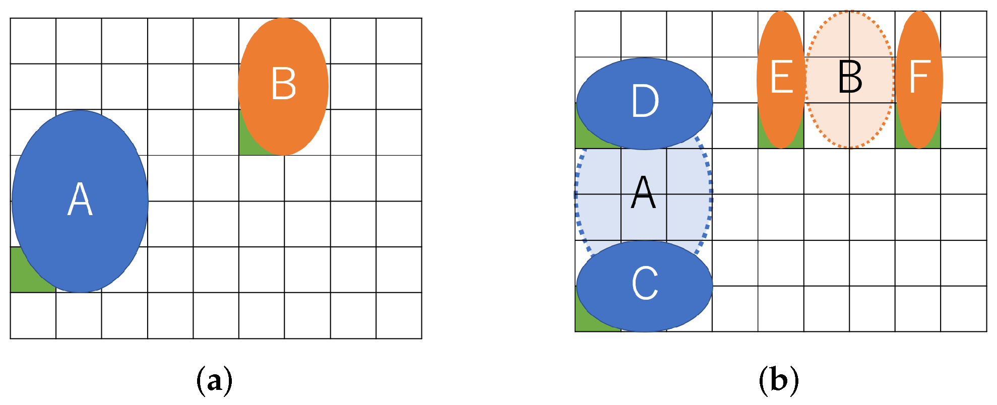
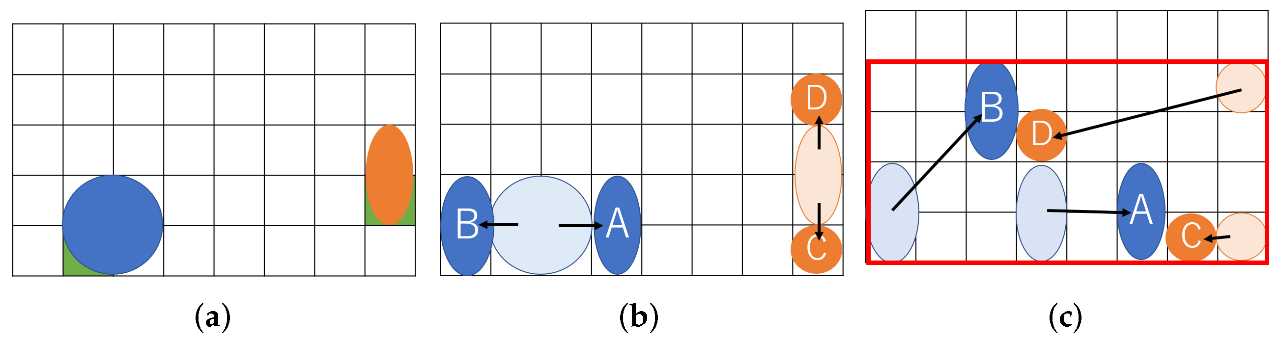
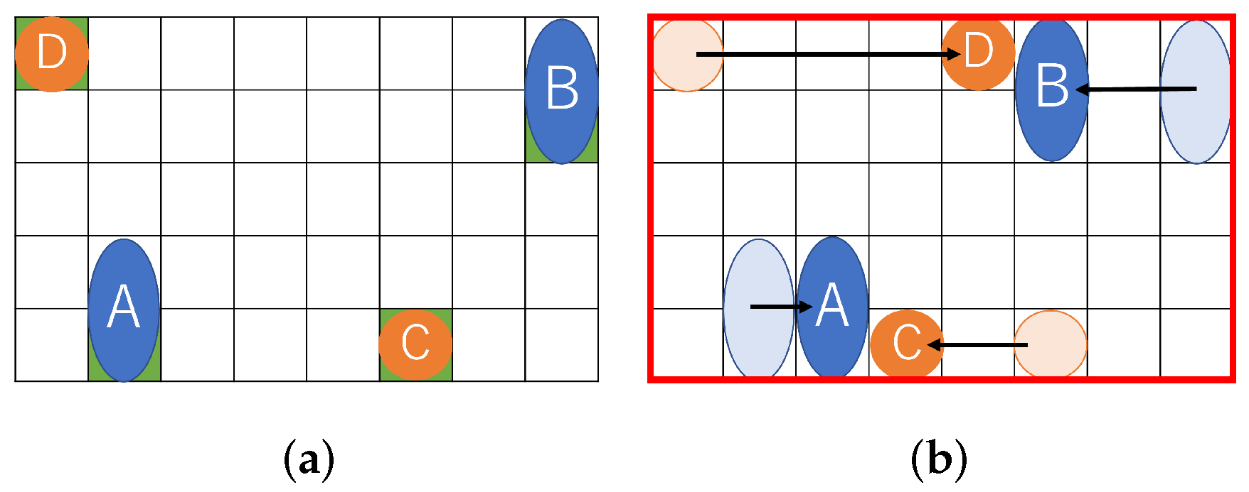
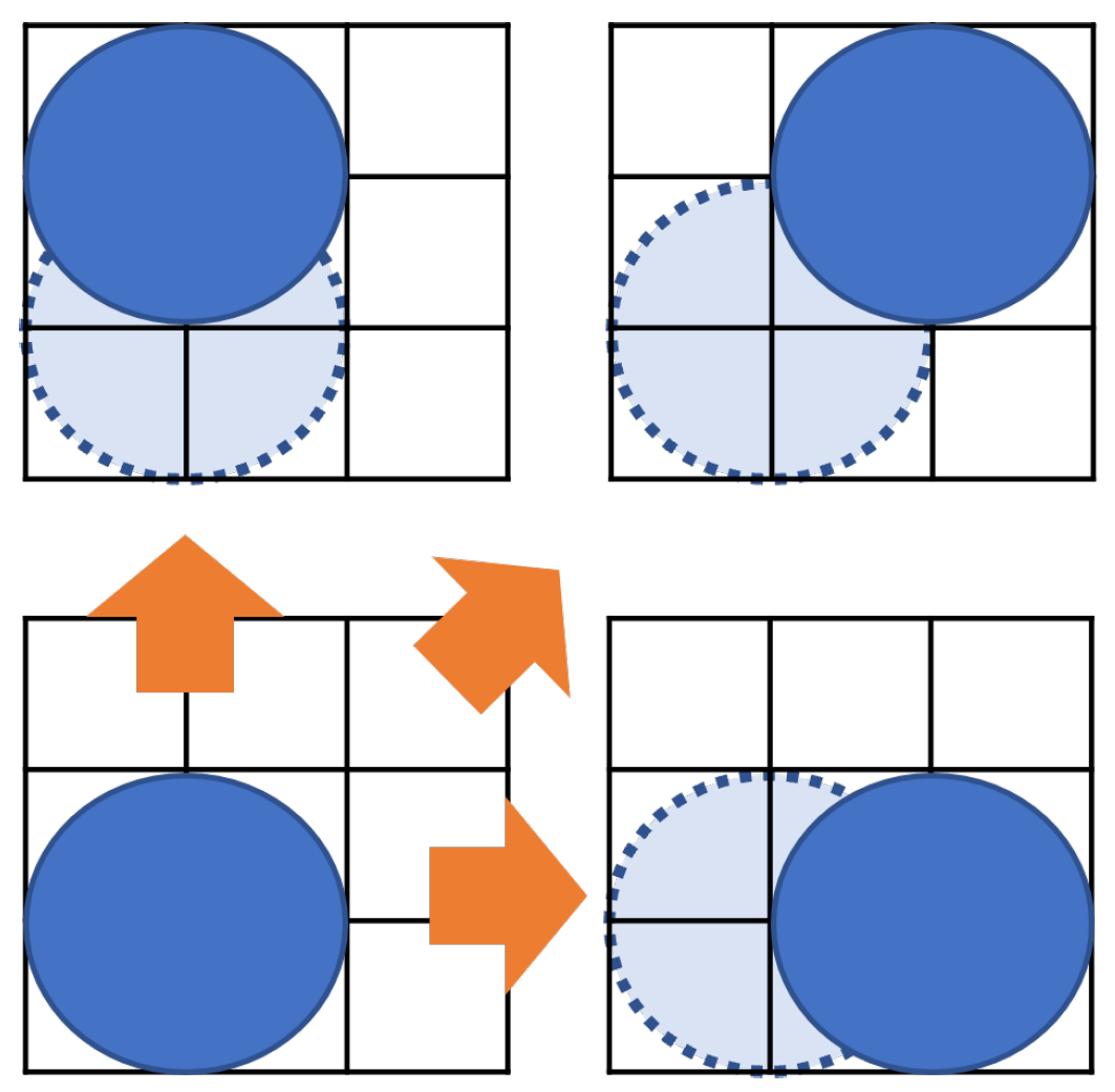
2.1. Problem Definition and Example
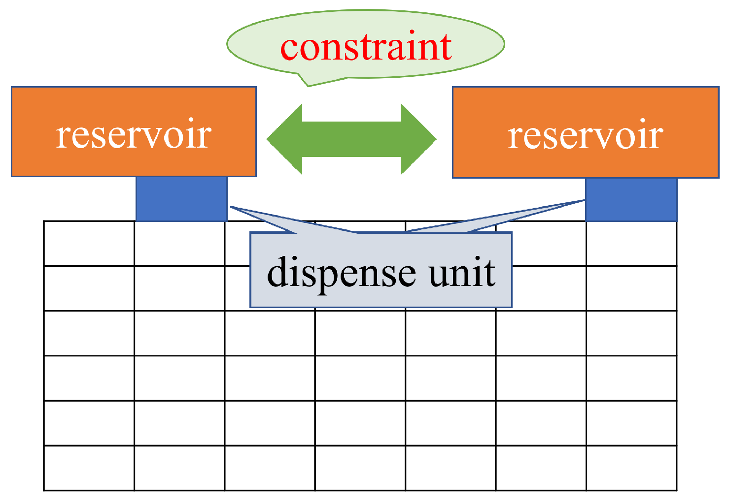
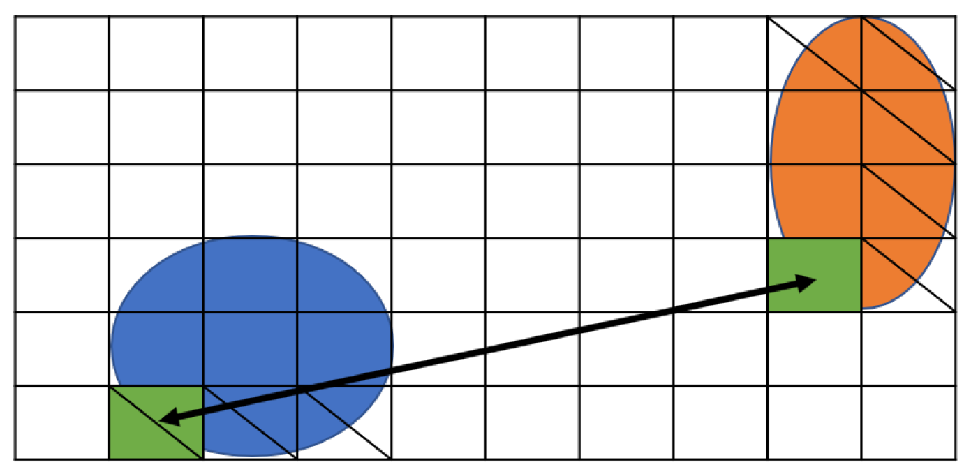
We define the droplet routing problem in MEDA biochips as follows: our routing problem in this paper assumes parallel homogeneous droplet routing with splitting operation. The problem assumes a couple of droplets be transported for mixing, and we allow the droplets to be split during routing. Given the number and size of droplets with a maximum limit of biochip size as a constraint, our routing determines the best routes such that the biochip size, which represents the rectangle constructed with the routing paths by the droplets, is minimized.
Figure 1 shows an example of our routing problem aware of dilution. Figure 1a represents a couple of droplets to be mixed on a MEDA biochip. The (8 × 5) rectangle indicates the biochip cells, and the two circles in blue and orange represent droplets. The blue droplet is called buffer and the orange one is called sample. The droplets initially occupy four and two cells, respectively. In order to address the coordinate of the cell, we define the reference point, which is green in the lower left corner of the droplet []. In this paper, we assume that each droplet is allowed to be split into two small droplets during routing. Figure 1b shows the split operation. If a droplet is an input without splitting, it must be input at a position far from the one shown in Figure 1b due to reservoir interference []. The sample droplet is split into A and B small droplets, and the buffer droplet is split into C and D. Assume that the size of each droplet is ( A , B , C , D ) = ( 2 , 2 , 1 , 1 ) and consider routing droplets to mix A and C and to do B and D as shown in Figure 1c. We show the routing path of the droplets and create a bounding box of the paths in Figure 1c. As shown in Figure 1c, the (8 × 4) rectangle on the biochip are required for transporting the droplets.
Figure 1. Routing example for a proposed method. (a) Initial position of droplets; (b) Split into small droplets; (c) Droplet position after routing.
Figure 2 shows a similar problem solved with existing a state-of-the-art method. A certain distance must be kept between droplets due to the dispensing unit. Figure 2a shows the initial position of the droplets assuming the constraints of the dispensing unit. After that, the droplets move for mixing. Figure 2b shows the positional relationship of each droplet after the droplet is moved. As shown in Figure 2b, the (8 × 5) rectangle on the biochip is required for transporting the droplets.
Figure 2. Routing example for a state-of-the-art method. (a) Initial position of droplets; (b) Droplet position after routing.
In the example, we had several assumptions towards the droplets. As shown in Figure 1b, the split droplets must be distant by a boundary width, and not interfere with each other. The droplets must keep a distance during transportation as well, otherwise the droplets obtain undesirable mixing. For simplicity, we neglect the density and volume errors of the droplets due to the contamination on the routing path by the droplets. Since the problem aims at the minimization of biochip size (the total size of the rectangle constructed by droplets passing), we do not take into account the speed of droplets.

2.2. Formulation

We formulate the problem for parallel droplet routing with splitting. Table 1 shows the notations used in the following formulation.
Table 1. Input data/Notations.
Formula (1) represents the constraint on the coordinates when the droplets are dispensed into the MEDA biochip []. ( x _ i n i t i , 0 , y _ i n i t i , 0 ) is the reference point ( x , y ) at the time of input of droplet i. Let t denote the time, and the droplet is input to the MEDA biochip at t = 0 . ( w _ i n i t i , h _ i n i t i ) is assumed to be the aspect ratio of droplet i, and we assume the shape of the droplets cannot be changed. At t = 0 , the droplets must be placed on an edge of the biochip.
i , ( x _ i n i t i , 0 = 1 ) ( x _ i n i t i , 0 + w _ i n i t i = W + 1 ) ( y _ i n i t i , 0 = 1 ) ( y _ i n i t i , 0 + h _ i n i t i = H + 1 )
Formula (2) represents the volume and shape of the droplet []. The aspect ratio of the droplet at the input is constant until it is split after it is determined by Formula (2). This constraint guarantees that the aspect ratio of a droplet is kept unchanged over time. w _ i n i t i , h _ i n i t i is the vertical and horizontal size of droplet i before splitting.
i , w _ i n i t i × h _ i n i t i = I n p u t _ V o l i
Formula (3) shows the constraints on the dispensing units for input to avoid fluidic leakage and dispensing clustering. Formula (3) determines the initial position of droplets. Considering the size of the dispensing units and the interference of the reservoir, the distance between the dispensing units must be greater than a certain value L R R [,]. Determining the initial position of the droplet is important because the biochip size is affected by the constraints of the dispensing unit. In this paper, the distance between two dispensing units is defined as the sum of twice the maximum edge of the droplet and the distance B. The formula (3) constrains its boundary width, as shown in Figure 3.
i 1 , i 2 , j , ( i 1 i 2 ) ,
| x _ i n i t i 1 , 0 x _ i n i t i 2 , 0 | + | y _ i n i t i 1 , 0 y _ i n i t i 2 , 0 | m a x i ( 2 × w _ i n i t i + B )
| x _ i n i t i 1 , 0 x _ i n i t i 2 , 0 + | y _ i n i t i 1 , 0 y _ i n i t i 2 , 0 | m a x i ( 2 × h _ i n i t i + B )
Figure 3. Distance between reservoirs.
Figure 4 shows the position of the droplet that satisfies Formulas (1) and (3). The shaded area in Figure 4 represents Formula (1).
Figure 4. Boundary width between the droplets.
The reference point when the droplet is transported before splitting is represented by Formula (4) []. p r e _ m o v e i , t is a 0–1 variable.
If droplet i moves before split at time t, p r e _ m o v e i , t becomes 1. Droplet i does not move before the split at time t, otherwise p r e _ m o v e i , t becomes 0. Unlike DMFBs, Droplets on the MEDA biochip can move not only in the horizontal and vertical directions, but also in the diagonal direction.
i , t , i f ( p r e _ m o v e i , t = 1 )
{ ( x _ i n i t i , t + 1 = x _ i n i t i , t ) ( x _ i n i t i , t + 1 = x _ i n i t i , t + 1 ) ( x _ i n i t i , t + 1 = x _ i n i t i , t 1 ) }
{ ( y _ i n i t i , t + 1 = y _ i n i t i , t ) ( y _ i n i t i , t + 1 = y _ i n i t i , t + 1 ) ( y _ i n i t i , t + 1 = y _ i n i t i , t 1 ) }
Formula (5) shows how to determine the aspect of the droplet after splitting. The aspect ratio of the droplet after splitting on the MEDA biochip remains fixed. Formula (5) expresses the relationship between droplet volume and droplet shape. This constraint also guarantees that the aspect ratio of a droplet is kept unchanged over time.
i , j , ( 0 t ) w _ m i x i , j × h _ m i x i , j = V o l i , j
When the droplets are split, Formula (6) represents the constraint for the case where the two droplets move up and down after a split, and Formula (7) represents the constraint for the case where the two droplets move left and right after the split. p r e i represents the time when the split of droplet i starts. w _ m i x i , j , t and h _ m i x i , j , t are the horizontal and vertical sizes of droplets i , j at time t. x _ a l i q u o t i , j and y _ a l i q u o t i , j are the coordinates of the reference point for the two of small droplets i and j after splitting.
i , j , p r e i { p r e i = m a x t ( t × p r e _ m o v e i , t ) } i f w _ i n i t i = w _ m i x i , j
j 1 , j 2 ( j 1 j 2 ) N u m _ d r o p l e t ( y _ a l i q u o t i , j 2 = y _ i n i t i , p r e i + h _ m i x i , j 1 + B ) ( y _ a l i q u o t i , j 1 = y _ i n i t i , p r e i B )
i , j , p r e i { p r e i = m a x t ( t × p r e _ m o v e i , t ) } i f h _ i n i t i = h _ m i x i , j
j 1 , j 2 ( j 1 j 2 ) N u m _ d r o p l e t ( x _ a l i q u o t i , j 2 = x _ i n i t i , p r e i + w _ m i x i , j 1 + B ) ( x _ a l i q u o t i , j 1 = x _ i n i t i , p r e i B ) }
Figure 5 shows the movement of droplets according to Formulas (6) and (7). There are two droplets, as shown in Figure 5a, and sample droplet A is vertically split into two small droplets C and D in Figure 5b. Droplet B is horizontally split to form droplet E and F. At splitting, the small droplets have to be distant more than the boundary width to avoid interference.
Figure 5. Location until routing starts. (a) Input droplets; (b) Splitting droplets.
In Formula (8), let x _ m i x i , j , t and y _ m i x i , j , t denote the coordinates of small droplets at time t. x _ m i x i , j , t and y _ m i x i , j , t represent the horizontal and vertical coordinates of the j-th droplet by the original droplet i, respectively. According to [,,], aliquot operation is assumed to take a second for splitting. Therefore, the time during aliquot operation is fixed as a certain time A l i q u o t , and which is taken into account in Formula (8).
i , j , t , { 1 t A l i q u o t + m a x t ( t × p r e _ m o v e i , t ) } x _ m i x i , j , t = x _ a l i q u o t i , j y _ m i x i , j , t = y _ a l i q u o t i , j
As shown in Figure 6, recall that the droplets on the MEDA biochip can move in the vertical, horizontal, and diagonal directions [,]. Formula (9) represents the constraint that the droplet ( i , j ) moves.
i , j , k , t , ( t t i m e _ m o v e i , j )
{ ( x _ m i x i , t + 1 = x _ m i x i , t ) ( x _ m i x i , t + 1 = x _ m i x i , t + 1 ) ( x _ m i x i , t + 1 = x _ m i x i , t 1 ) }
{ ( y _ m i x i , t + 1 = y _ m i x i , t ) ( y _ m i x i , t + 1 = y _ m i x i , t + 1 ) ( y _ m i x i , t + 1 = y _ m i x i , t 1 ) }
Figure 6. Position of droplets at input.
Formula (10) represents static and dynamic constraints to prevent undesirable mixing and interference between droplets []. Let d 1 and d 2 denote 0–1 decision variables. When d 1 = d 2 , Formula (10) represents static constraints, and when d 1 d 2 , Formula (10) represents dynamic constraints.
i 1 , i 2 , j 1 , j 2 , t , d 1 , d 2 , ( d 1 , d 2 , = 0 o r 1 ) i f ( j 1 j 2 )
{ y _ m i x i 1 , j 1 , t d 1 ( y _ m i x i 2 , j 2 , t d 2 + h _ m i x i 2 , j 2 ) B + 1 } { x _ m i x i 1 , j 1 , t d 1 ( x _ m i x i 2 , j 2 , t d 2 + w _ m i x i 2 , j 2 ) B + 1 }
In this problem, we are routing the two couples of droplets until they both start mixing. Formula (11) calculates the biochip size required for the routing operation up to this point.
S = { m a x i , j , k ( x _ m i x i , j , k + w _ m i x i , j ) m i n i , j , k ( x _ m i x i , j , k ) } × { m a x i , j , k ( y _ m i x i , j , k + h _ m i x i , j ) m i n i , j , k ( y _ m i x i , j , k ) }
These are the formulations that we have realized in this paper. When the aspect ratio of the droplet is freely varied in [], Formulae (2) and (5) are changed as in Formulas (12) and (13). To avoid unavailable cells, a change in the aspect ratio of the droplet is used. In this method, there are no unavailable cells, so it is not implemented.
i , t , w _ i n i t i , t × h _ i n i t i , t = W _ p r e _ i n i t i × H _ p r e _ i n i t i
i , j , t , ( 0 t ) w _ m i x i , j , t × h _ m i x i , j , t = V o l i , j

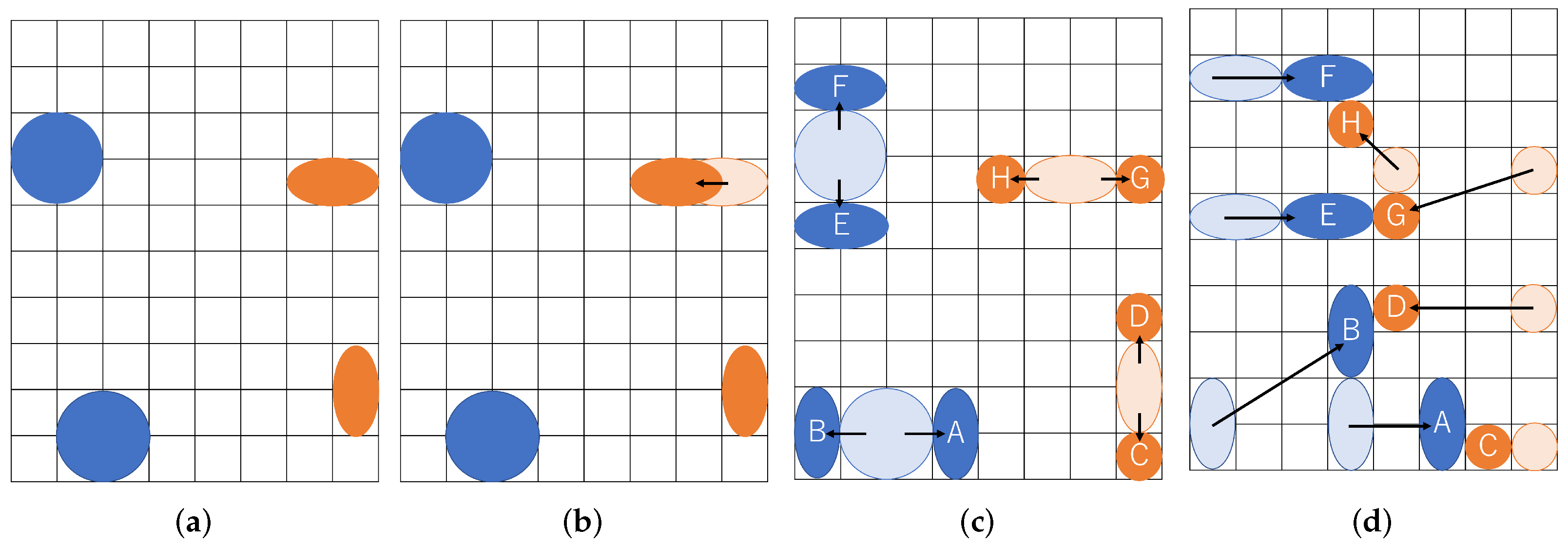
2.3. Multiple Couples of Droplets Routing
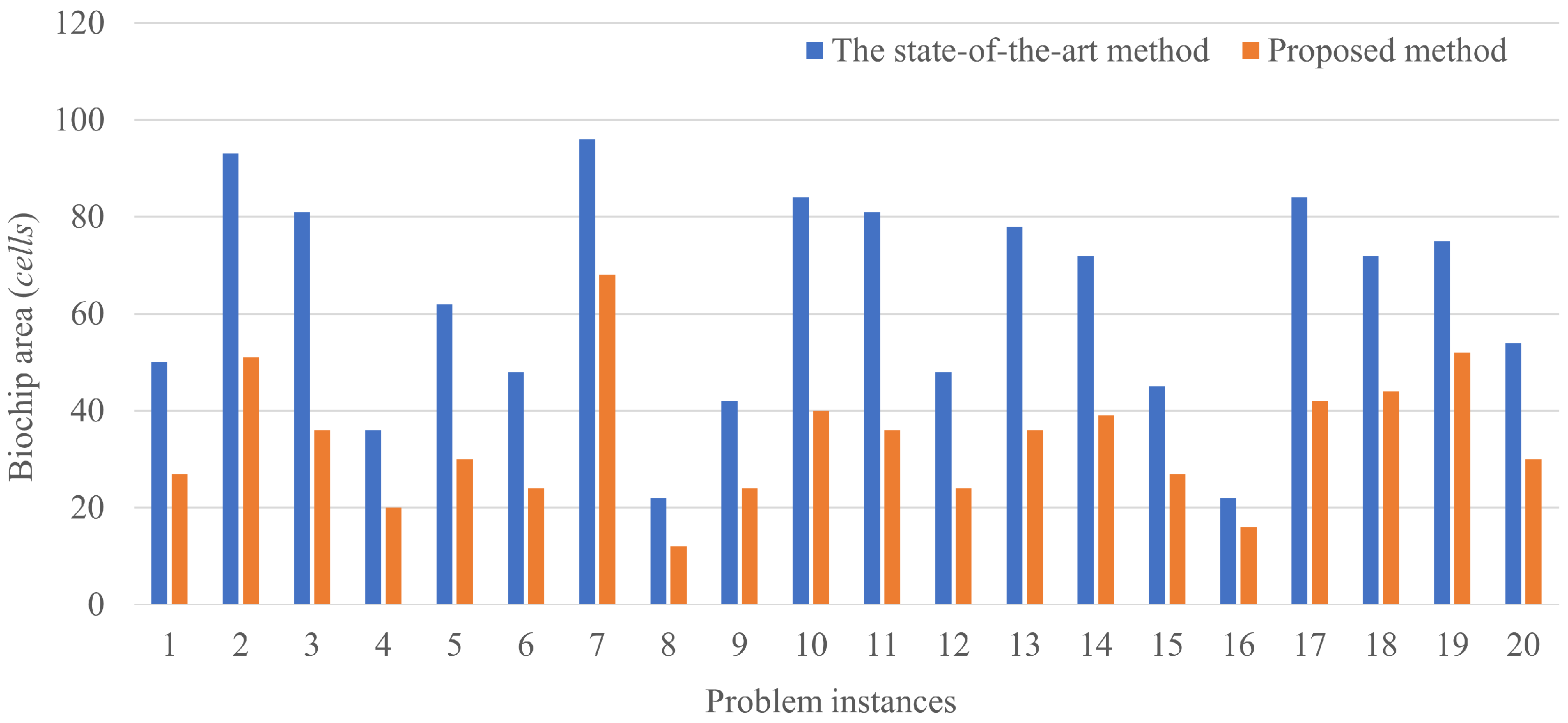
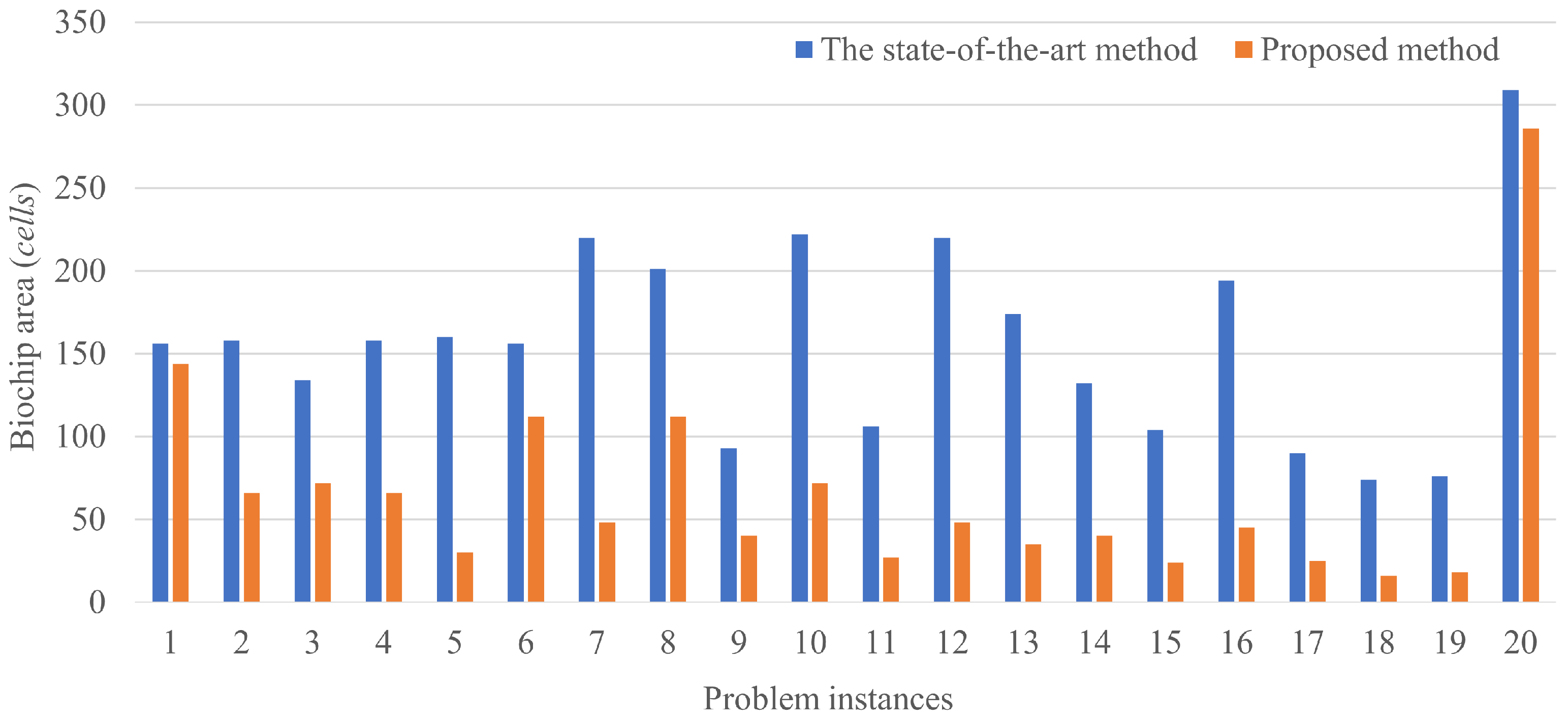
Homogeneous droplet routing generally asks for the accurate density and volume to achieve high reliability in manipulations such as dilution and mixing. In the real world, however, the microelectrode degradation and contamination may lead to mixing failure. In many cases, error recovery systems try to separate the mixed droplet into independent original droplets, modify the density and volume, and attempt to accurately remix them with a goal of improving the reliability [].
Another approach to high reliability in mixing is to conduct multiple mixing operations in parallel. For example, consider the mixing operation for droplet (A + C) and droplet (B + D) in Figure 1c of the previous subsection again. Even if mixing of (A + C) is failed due to the microelectrode degradation or contamination on the cells, the other mixing (B + D) may be conducted accurately. If both mixing operations fail, the operations are iteratively conducted until mixing has been accomplished. However, such a scenario unfortunately results in low throughput outcomes. This section extends the proposed method in the previous section to use a number of couples of droplets for high reliability.
We give an example of our multiple couples of droplets routing in Figure 7. Two couples of droplets are transported to be mixed. Each mixing operation is aimed at two cells of the buffer droplet and four cells of sample droplet. As illustrated in the figure, each size of the droplets is represented as ( A , B , C , D , E , F , G , H ) = ( 2 , 2 , 1 , 1 , 2 , 2 , 1 , 1 ) , and droplets are routed to mix A and C, B and D, E and G, and F and H, respectively. The resultant route in the example is shown in Figure 7d. The split operation transitions from the state in Figure 7a to the state in Figure 7c through the state in Figure 7b. Figure 7a shows the positional relationship immediately after input from the dispensing unit. In Figure 7c, the droplets are separated by the boundary width, which is the distance where they do not interfere with each other.
Figure 7. Multiple couples of droplets routing. (a) Input droplets; (b) Transportation before splitting; (c) Splitting droplets; (d) Transportation of small droplets.
Multiple couples of droplet routing are mainly based on the proposed method addressed in the previous section.
We can easily realize the routing method with the transformation from Formula (1) into Formula (14). The subscript s indicates an integer for the total kinds of droplets.
s , i , ( x _ i n i t s , i , 0 = 1 ) ( x _ i n i t s , i , 0 + w _ i n i t s , i = W + 1 ) ( y _ i n i t s , i , 0 = 1 ) ( y _ i n i t s , i , 0 + h _ i n i t s , i = H + 1 )

3. Experiments

3.1. Setup

We have conducted the experiments to demonstrate the effectiveness of our proposed method in simulation. We give the kind, number, and size of droplets, and the couples of droplets to be mixed are determined before routing. We assume that all droplets move at the same speed. Droplet velocity does not affect biochip size. The initial position of the droplet is determined according to the constraints of the dispensing unit. The goal of the routing problem is to minimize the biochip size on the biochip. We compare the biochip size with the following two methods.
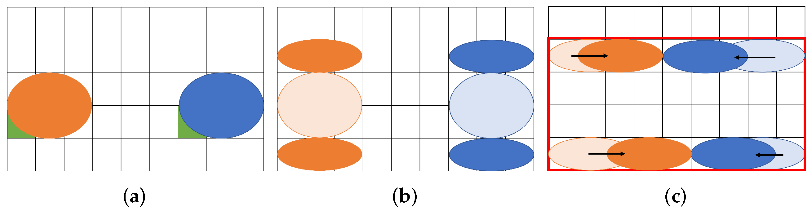
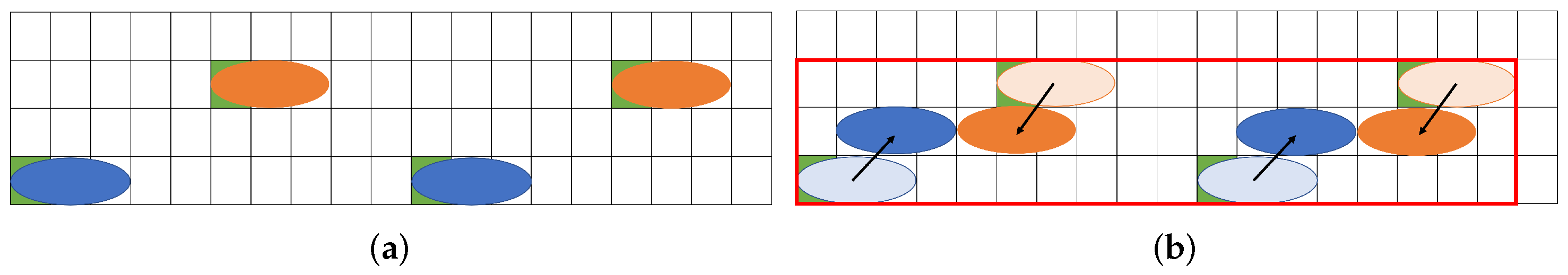
  • A state-of-the-art method presented in [], which initially inputs four/eight droplets onto the biochip for each experimental scenario.
  • The proposed method inputs two/four droplets and splits them into four/eight droplets for each experimental scenario.
In the experiments, we are given the size of the biochip as ( 200 × 200 ) . The experiments have been conducted on Intel Core i9-7980XE 2.60GHz with 128GB memory. IBM ILOG CPLEX Optimization Studio 20.1.0 is used for both the state-of-the-art method and the proposed method.
In the experiments, we assume two experimental scenarios. The former experimental scenario is a couple of droplets routing to create two resultant droplets, and the second experiment is multiple couples of droplets routing to create four resultant droplets by mixing operations. In this experimental scenario, the size of each droplet is assumed to be given randomly, which is shown in Table 2. This scenario assumes to solve the problem for mixing of droplets A and C and of droplets B and D. The runtime is limited by up to 10 h in CPU time. If an optimal solution is failed to be found within the runtime, the solution at the time limit is employed for comparison.
Table 2. The volume of droplets for droplet routing problems.
Similarly, routing of multiple couples of droplets assumes that the size of each droplet is given, as shown in Table 3. Unlike routing of a couple of droplets, this scenario assumes multiple couples of droplets go into mixing. The limit of the runtime is set to 50 h due to considering the computational complexity of the problem.
Table 3. The volume of droplets for multiple couples of droplet routing problems.

3.2. Results

The results of routing a couple of droplets are shown in Figure 8. The horizontal axis shows the problem instances and the vertical axis shows the biochip size, where the total number of the cells is passed by the droplets.
Figure 8. Results of a couple of droplet routings.
Figure 9 and Figure 10 show the trajectory of droplet movements in Case 1. Figure 9 shows the trajectory of Case 1 solved using the proposed method. The biochip size can be calculated to be 36 ( 9 × 4 ) . Figure 10 shows the trajectory of Case 1 solved by the state-of-the art method. The biochip size can be calculated to be 51 ( 17 × 3 ) . All the results show that the biochip size of the proposed method achieved less than the state-of-the-art method. The proposed method approximately reduces the biochip size by 56.3% on average. The results are attributed to the distance between dispensing units of the droplets in the state-of-the-art method. If the multiple droplets are independently input by dispensing units, the input droplets are distant due to the placement constraint of the dispensing units. Otherwise, the input droplets are interfered by each other, resulting undesirable manipulations as the error. On the other hand, if large droplets are initially input, the boundary width between the droplets is necessary to be distant to avoid the interference. However, even taking into account the effect of such distances, splitting operation of the droplets during routing by our proposed method can achieve the reduction of the biochip size, compared to the state-of-the-art method. The constraint on the initial position of the droplet is related to the biochip size. The closer the initial position of the droplets are to the mixing droplets, the smaller the biochip size is.
Figure 9. Trajectory of droplet movement in the proposed method. (a) Input droplets; (b) Split droplets; (c) Finish routing.
Figure 10. Trajectory of droplet movement in the state-of-the art method. (a) Input droplets; (b) Finish routing.
Figure 11 shows the results of multiple couples of droplet routing. Even if the number of droplets is increased, our proposed method demonstrates the effectiveness compared to the state-of-the-art method. The results show that the biochip size obtained by the proposed method is reduced by up to 81.4% and by 56.2% on average. Specifically, Case 1 and Case 20 show that our method achieves the slight reduction of the biochip size. As aforementioned, the state-of-the-art method fails to reduce the biochip size in the case with the large droplets.
Figure 11. Results of multiple couples of droplets routing.
Through these experiments, we demonstrate that the proposed method outperforms the state-of-the-art method. With the reduction of the biochip size, we imply that other manipulations will be conducted. In addition, the microelectrode degradation and contamination on the cells are taken into account in the future.

4. Conclusions

We have proposed the routing method to reduce the biochip size, allowing the splitting operation during routing. In addition, we extend our proposed method to multiple couples of droplet routing to aim at high reliability and throughput by exploiting the potential of the MEDA biochip. In the experimental results, our proposed method outperforms the state-of-the-art method and dramatically reduces the biochip size in routing.
We imply that our contribution enables other biochemical manipulations at the same time on the biochip. The proposed method, however, additionally requires splitting operations unlike the state-of-the-art method, and the operation may produce the error of the density and volume. In the future, we plan to deal with the issues above. Moreover, we will develop error-tolerant techniques for droplet routing.

Author Contributions

Conceptualization, C.S.; Formal analysis, C.S.; Data curation, C.S.; Funding acquisition, H.N., X.K., H.T. and S.Y.; Investigation, C.S.; Methodology, C.S.; Software, C.S.; Project administration, H.N. and H.T.; Supervision, H.N., X.K., H.T. and S.Y.; Validation, C.S.; Writing—original draft, C.S.; Writing—review and editing, H.N., X.K., H.T. and S.Y. All authors have read and agreed to the published version of the manuscript.

Funding

This work is supported partly by KAKENHI 20H04160, 20H00590, and 20J21208.

Institutional Review Board Statement

Not applicable.

Data Availability Statement

Not applicable.

Conflicts of Interest

The authors declare no conflict of interest.

References

  1. Gibson, L.L.; Fahey, N.M.; Hafer, N.; Buchholz, B.; Dunlap, D.R.; Murphy, R.L.; Achenbach, C.; Stone, C.; Cleeton, R.; O’Neal, J.; et al. The RADx Tech Clinical Studies Core: A Model for Academic Based Clinical Studies. IEEE Open J. Eng. Med. Biol. 2021, 2, 152–157. [Google Scholar] [CrossRef] [PubMed]
  2. Gou, Y.; Liu, J.; Sun, C.; Wang, P.; You, Z.; Ren, D. Inertial-Assisted Immunomagnetic Bioplatform towards Efficient Enrichment of Circulating Tumor Cells. Biosensors 2021, 11, 183. [Google Scholar] [CrossRef] [PubMed]
  3. Kutateladze, T.; Bitskinashvili, K.; Sapojnikova, N.; Kartvelishvili, T.; Asatiani, N.; Vishnepolsky, B.; Datukishvili, N. Development of Multiplex PCR Coupled DNA Chip Technology for Assessment of Endogenous and Exogenous Allergens in GM Soybean. Biosensors 2021, 11, 481. [Google Scholar] [CrossRef] [PubMed]
  4. Kim, Y.; Yang, J.; Hur, H.; Oh, S.; Lee, H. Highly Sensitive Colorimetric Assay of Cortisol Using Cortisol Antibody and Aptamer Sandwich Assay. Biosensors 2021, 11, 163. [Google Scholar] [CrossRef] [PubMed]
  5. Tsounidi, D.; Koukouvinos, G.; Christianidis, V.; Legaki, E.; Giogli, V.; Panagiotopoulou, K.; Taka, S.; Ekaterinidi, Z.; Kakabakos, S.; Raptis, I.; et al. Development of a Point-of-Care System Based on White Light Reflectance Spectroscopy: Application in CRP Determination. Biosensors 2021, 11, 268. [Google Scholar] [CrossRef]
  6. Sun, F.; Ganguli, A.; Nguyen, J.; Brisbin, R.; Shanmugam, K.; Hirschberg, D.L.; Wheeler, M.B.; Bashir, R.; Nash, D.M.; Cunningham, B.T. Smartphone-based multiplex 30-minute nucleic acid test of live virus from nasal swab extract. Lab Chip 2020, 20, 1621–1627. [Google Scholar] [CrossRef]
  7. Zeng, J.; Korsmeyer, T. Principles of droplet electrohydrodynamics for lab-on-a-chip. Lab Chip 2004, 4, 265–277. [Google Scholar] [CrossRef]
  8. Fei, S.; Chakrabarty, K. Architectural-level synthesis of digital microfluidics-based biochips. In Proceedings of the IEEE/ACM International Conference on Computer Aided Design, San Jose, CA, USA, 7–11 November 2004; pp. 223–228. [Google Scholar]
  9. Fair, R.B. Digital microfluidics: Is a true lab-on-a-chip possible? Microfluid. Nanofluidics 2007, 3, 245–281. [Google Scholar] [CrossRef]
  10. Keszocze, O.; Wille, R.; Drechsler, R. Exact routing for digital microfluidic biochips with temporary blockages. In Proceedings of the International Conference on Computer-Aided Design, San Jose, CA, USA, 2–6 November 2014. [Google Scholar]
  11. Keszocze, O.; Li, Z.; Grimmer, A.; Wille, R.; Chakrabarty, K.; Drechsler, R. Exact routing for micro-electrode-dot-array digital microfluidic biochips. In Proceedings of the Asia and South Pacific Design Automation Conference, Chiba, Japan, 16–19 January 2017. [Google Scholar]
  12. Liang, T.C.; Zhou, J.; Ho, T.-Y.; Chakrabarty, K.; Lee, C.-Y. Parallel droplet control in MEDA biochips using multi-agent reinforcement learning. In Proceedings of the International Conference on Machine Learning, Online, 18–24 July 2021; pp. 6588–6599. [Google Scholar]
  13. Das, C.; Muhuri, S.; Chakraborty, S.; Chakraborty, S. Security assessment for routing-based synthesis on cyberphysical MEDA-based digital microfluidic biochip. SN Appl. Sci. 2021, 3, 1–19. [Google Scholar] [CrossRef]
  14. Chakraborty, S.; Chakraborty, S. Routing performance optimization for homogeneous droplets on MEDA-based digital microfluidic biochips. In Proceedings of the Computer Society Annual Symposium on VLSI, Miami, FL, USA, 15–17 July 2019. [Google Scholar]
  15. Howladar, P.; Roy, P.; Rahaman, H. A High-performance Homogeneous Droplet Routing Technique for MEDA-based Biochips. ACM J. Emerg. Technol. Comput. Syst. 2019, 15, 1–37. [Google Scholar] [CrossRef]
  16. Shiro, C.; Nishikawa, H.; Kong, X.; Tomiyama, H.; Yamashita, S. Minimization of Routing Area in MEDA Biochips. In Proceedings of the IEEE Biomedical Circuits and Systems Conference (BioCAS), Berlin, Germany, 7–9 October 2021; pp. 1–5. [Google Scholar]
  17. Gao, L.; Lv, Q.; Xia, N.; Lin, Y.; Lin, F.; Han, B. Detection of Mercury Ion with High Sensitivity and Selectivity Using a DNA/Graphene Oxide Hybrid Immobilized on Glass Slides. Biosensors 2021, 11, 300. [Google Scholar] [CrossRef] [PubMed]
  18. Seok, Y.; Lee, J.; Kim, M.-G. Paper-Based Airborne Bacteria Collection and DNA Extraction Kit. Biosensors 2021, 11, 375. [Google Scholar] [CrossRef] [PubMed]
  19. Ferrari, E.; Palma, C.; Vesentini, S.; Occhetta, P.; Rasponi, M. Integrating Biosensors in Organs-on-Chip Devices: A Perspective on Current Strategies to Monitor Microphysiological Systems. Biosensors 2020, 10, 110. [Google Scholar] [CrossRef] [PubMed]
  20. Yang, L. A Review of Multifunctions of Dielectrophoresis in Biosensors and Biochips for Bacteria Detection. Anal. Lett. 2012, 45, 187–201. [Google Scholar] [CrossRef]
  21. Cho, M.; Pan, D.Z. A High-Performance Droplet Routing Algorithm for Digital Microfluidic Biochips. IEEE Trans. Comput. Des. Integr. Circuits Syst. 2008, 27, 1714–1724. [Google Scholar] [CrossRef]
  22. Keszocze, O.; Wille, R.; Chakrabarty, K.; Drechsler, R. A general and exact routing methodology for Digital Microfluidic Biochips. In Proceedings of the 2015 IEEE/ACM International Conference on Computer-Aided Design (ICCAD), Austin, TX, USA, 2–6 November 2015; pp. 874–881. [Google Scholar] [CrossRef]
  23. Liang, T.C.; Zhong, Z. Adaptive droplet routing in digital microfluidic biochips using deep reinforcement learning. In Proceedings of the International Conference on Machine Learning, Online, 13–18 July 2020; pp. 6050–6060. [Google Scholar]
  24. Zhong, Z.; Li, Z.; Chakrabarty, K.; Ho, T.; Lee, C. Micro-electrode-dot-array digital microfluidic biochips: Technology, design automation, and test techniques. IEEE Trans. Biomed. Circuits Syst. 2018, 13, 292–313. [Google Scholar] [CrossRef] [PubMed]
  25. Li, Z.; Lai, K.Y.-T.; Yu, P.-H.; Ho, T.-Y.; Chakrabarty, K.; Lee, C.-Y. High-level synthesis for micro-electrode-dot-array digital microfluidic biochips. In Proceedings of the 2016 53nd ACM/EDAC/IEEE Design Automation Conference (DAC), Austin, TX, USA, 5–9 June 2016; p. 146. [Google Scholar] [CrossRef]
  26. Zhong, Z.; Liang, T.-C.; Chakrabarty, K. Reliability-Oriented IEEE Std. 1687 Network Design and Block-Aware High-Level Synthesis for MEDA Biochips*. In Proceedings of the 2020 25th Asia and South Pacific Design Automation Conference (ASP-DAC), Beijing, China, 13–16 January 2020; pp. 544–549. [Google Scholar] [CrossRef]
  27. Li, Z.; Lai, K.Y.-T.; Yu, P.-H.; Chakrabarty, K.; Ho, T.-Y.; Lee, C.-Y. Droplet Size-Aware High-Level Synthesis for Micro-Electrode-Dot-Array Digital Microfluidic Biochips. IEEE Trans. Biomed. Circuits Syst. 2017, 11, 612–626. [Google Scholar] [CrossRef] [PubMed]
  28. Roy, P.; Banerjee, A.; Wille, R.; Bhattacharya, B.B. Harnessing the Granularity of Micro-Electrode-Dot-Array Architectures for Optimizing Droplet Routing in Biochips. ACM Trans. Des. Autom. Electron. Syst. 2020, 25, 1–37. [Google Scholar] [CrossRef] [Green Version]
  29. Lai, K.Y.-T.; Yang, Y.-T.; Lee, C.-Y. An Intelligent Digital Microfluidic Processor for Biomedical Detection. J. Signal Process. Syst. 2014, 78, 85–93. [Google Scholar] [CrossRef]
  30. Lu, G.; Bhattacharya, B.B.; Tsung, H.; Hung, C. Multi-level droplet routing in active-matrix based digital-microfluidic biochips. In Proceedings of the Asia and South Pacific Design Automation Conference, Jeju, Korea, 22–25 January 2018. [Google Scholar]
  31. Luo, Y.; Bhattacharya, B.B.; Ho, T.-Y.; Chakrabarty, K. Design and Optimization of a Cyberphysical Digital-Microfluidic Biochip for the Polymerase Chain Reaction. IEEE Trans. Comput. Des. Integr. Circuits Syst. 2014, 34, 29–42. [Google Scholar] [CrossRef]
  32. Zhong, Z.; Li, Z.; Chakrabarty, K. Adaptive error recovery in MEDA biochips based on droplet-aliquot operations and predictive analysis. In Proceedings of the International Conference on Computer-Aided Design, Irvine, CA, USA, 12–16 November 2017; pp. 615–622. [Google Scholar]
  33. Zhong, Z.; Li, Z.; Chakrabarty, K. Adaptive and Roll-Forward Error Recovery in MEDA Biochips Based on Droplet-Aliquot Operations and Predictive Analysis. IEEE Trans. Multi-Scale Comput. Syst. 2018, 4, 577–592. [Google Scholar] [CrossRef]
  34. Wang, G. Field-Programmable Microfluidic Test Platform for Point-of-Care Diagnostics. Ph.D. Thesis, University of Saskatchewan, Saskatoon, Canada, 2013. [Google Scholar]
  35. Luo, Y.; Chakrabarty, K.; Ho, T. Error Recovery in Cyberphysical Digital Microfluidic Biochips. IEEE Trans. Comput. Aided Des. Integr. Circuits Syst. 2012, 32, 59–72. [Google Scholar] [CrossRef]
Publisher’s Note: MDPI stays neutral with regard to jurisdictional claims in published maps and institutional affiliations.

Article Metrics

Citations

Article Access Statistics

Multiple requests from the same IP address are counted as one view.