Article

Polarization and Trap Characteristics Modification of Oil-Impregnated Paper Insulation by TiO2 Nanoparticles

1
Beijing Key Laboratory of High Voltage & EMC, North China Electric Power University, Beijing 102206, China
2
State Key Laboratory of Alternate Electrical Power System with Renewable Energy Sources, North China Electric Power University, Beijing 102206, China
3
School of Energy, Power and Mechanical Engineering, North China Electric Power University, Beijing 102206, China
*
Author to whom correspondence should be addressed.
Nanomaterials 2019, 9(2), 174; https://doi.org/10.3390/nano9020174
Submission received: 7 January 2019 / Revised: 21 January 2019 / Accepted: 29 January 2019 / Published: 31 January 2019

Abstract

:
Polarization and traps determine the electrical property of oil-paper insulation, but most attention has been paid to the modification of insulating oil with nanoparticles, so there are is little research about oil-impregnated paper, and the origin for performance variation is not understood yet. In this paper, spherical nanoscale titanium dioxide was prepared by the hydrolysis method and nanofluid-impregnated paper (NP) was fabricated through oil-impregnation. The frequency domain spectrum was measured for polarization analysis, and both thermally stimulated depolarization current (TSDC) and isothermal surface potential decay (ISPD) methods were used to reveal trap parameters. Results show that NP’s low frequency permittivity is much larger, and another peak appears in the spectrum even though the content of nanoparticles is very low. With the addition of TiO2 nanoparticles, TSDC’s amplitude and peak temperature increase, and the trap energy becomes shallower. TiO2 nanoparticles’ strong polarization and high activation energy contribute to NP’s larger interface polarization intensity and activation energy. Furthermore, because of oxygen vacancies, TiO2 nanoparticles offer a transfer site for holes and electrons to escape from deep traps; thus, the trap energy is greatly reduced.

1. Introduction

Owing to its excellent electrical performance, oil-paper insulation has been widely used as the main insulating material in large quantities of equipment, such as transformers and cables. However, the development of the electric industry demands miniaturization, large-capacities, and high-reliability for equipment, which challenges the electrical property of conventional oil-paper insulation. The appearance of nanotechnology offers a novel solution to improve oil-paper insulation’s electrical strength by adding nanoparticles [1].
Oil-paper insulation is a kind of complex material which contains liquid and solid dielectrics, so the modification needs to be handled carefully. Since it was found that the breakdown strength of mineral oil can be increased with Fe3O4 nanoparticles in 1988 [2], it has attracted more and more attention. Different kinds of nanoparticles have been used for the modification of insulating oil, including conductive, semi-conductive, and insulated ones, and the influence of shapes and sizes have been considered as well [2,3,4,5,6,7]. The electrical properties of nanofluids such as breakdown strength and streamer propagation have indeed been markedly improved, and it has been commonly accepted that this is attributed to the variation of dielectric relaxation and trap energy caused by nanoparticles [8,9].
As for the solid component, namely paper or pressboard, it has to be impregnated with oil in application; therefore, its property improvement is usually focused on the modification of oil-impregnated paper or pressboard (both named OP), but there is little research compared to that of oil. Paper is made by pressing fiber together. There are many small pores in it, and therefore the nanoparticles can be made to be absorbed on the surface of fiber before papermaking [10] or transported through the pores and deposited during oil-impregnation [3]. With the modification of nanoparticles, the partial discharge, surface discharge, and breakdown performance of OP can be perfected to some degree [10,11,12]. These changes are believed to be strongly linked to dielectric polarization and space charge suppression [11,12]. Permittivity of modified OP depends on nanoparticles’ type, which can be either decreased—by SiO2 nanoparticles, for instance—or increased—by TiO2 nanoparticles, for instance [10,13]. Charge accumulation behavior of AlN-modified OP is found to be affected by nanoparticle concentration because of the competition between the interfacial and the agglomeration effect, and, furthermore, the property may instead suffer under some conditions [14]. The electric field distribution within OP is closely related to its electrical property, including breakdown and partial discharge, which is determined by permittivity and space charge [12,15,16]. Nevertheless, the underlying reason for their variations in modified OP has not yet been clearly demonstrated; therefore, the influence of nanoparticles on polarization and trap characteristics requires consideration.
In this paper, anatase-TiO2 nanoparticles were used for modification through the oil-impregnation method, and their effect on polarization and trap distribution was analyzed to reveal the behind mechanism. In addition to an interface increase, TiO2 nanoparticles’ large permittivity leads to a strong interface polarization of the nanofluid-impregnated paper or pressboard (both named NP) with higher activation energy. The oxygen vacancies from TiO2 nanoparticles help the trapped charge to dissipate and will thus weaken the electric field distribution.

2. Materials and Methods

Nanoscale titanium dioxide was prepared by the hydrolysis method using four butyl titanate as the titanium source and oleic acid as the surface modifier. Sizes of spherical nanoparticles can be controlled by adjusting the reaction environment, such as the amount of oleic acid and temperature [3]. Under proper conditions, 10 nm TiO2 nanoparticles—the transmission electron microscopy (TEM) image of which is shown in Figure 1—were fabricated, and they were then dispersed into the strictly filtered mineral transformer oil (Karamay 25#) which fulfilled the quota by CIGRE working group 12.17.10 through the ultrasonic method [3]. The concentration of nanoparticles in the nanofluid was 0.075 vol%. Before impregnation, the 1 mm thick B3.1 type pressboard from Weidmann Company was also carefully handled. It was first cut into pieces with sizes of 85 mm × 60 mm. Then, they were put into a ventilated 105 °C oven for 48 h to remove the moisture. After that, these pressboard pieces were put into a 1 kPa/85 °C vacuum for 48 h. The nanofluid and pure transformer oil were treated in the same way. After that, dried pressboards were put into either pure oil or nanofluid in a 1 kPa/80 °C vacuum for 48 h for oil-impregnation. Through these pretreatments, the moisture content of both OP and NP did not exceed 0.5%.
Trap distribution characteristics of NP and OP were measured by both thermally stimulated depolarization current (TSDC) and isothermal surface potential decay (ISPD) methods. The schematic diagrams are demonstrated in Figure 2. Details of TSDC measurement can be found in our previous paper [17]. In regard to the ISPD method, it consisted of two processes—namely surface charging and surface potential measurement. During the surface charging process, a needle electrode connected to high voltage was used for ion generation of either sign through corona discharge. The wire mesh grid was used to generate a uniform field between the mesh grid and ground electrode for a better charge [18]. The needle electrode was applied with ±6 kV and the mesh grid was connected to ±3 kV DC voltage. Immediately after the corona discharge, the sample was quickly transferred to below the Kelvin probe for isothermal surface potential measurement through the rotating grounded electrode. The distance between the sample and non-contact probe (Trek P0865) was fixed at 2 mm. At the beginning of the ISPD experiment, the ground potential calibration was carried out.
An inductively coupled plasma optical emission spectrometer (Agilent 5110 ICP-OES) was used to detect the content of titanium element in both OP and NP. The frequency domain spectrum of their permittivity was measured by an IDAX 300 Insulation Diagnostic Analyzer at ambient temperature, with the voltage being fixed to 140 V.

3. Results

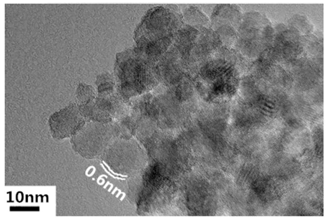
3.1. Content of Titanium Element

The impregnated pressboards can be divided into five layers for measurement of the content of titanium element, as shown in Figure 3. Results for both NP and OP are listed in Table 1. Those of NP which had been scoured with pure oil through stirring for different times are included in Table 1 as well.
Though there was no titanium element in OP, there was such a high content of titanium element in NP due to the diffusion of TiO2 nanoparticles. The content reached as high as 160.0 ppm in the outer layer, and it decreased gradually from the outer surface to the inner layer. Scoured with pure oil, the content of titanium element in NP decreased obviously, but the deeper from the outer surface, the smaller the content variation. For example, content of titanium element of the outer layer reduced from 160.0 ppm to 10.2 ppm when it had been washed for 168 h, while it just changed from 44.5 ppm to 31.2 ppm for the inner layer. If the time duration of scouring had extended to 336 h, the content varied much more apparently. This meant that there was no direct bond formation between nanoparticles and cellulose in NP, and they just stayed in the small pores within the pressboards, which can diffuse through NP along with the movement of oil.

3.2. Frequency Domain Spectrum

The frequency domain spectrum of both OP and NP (170 μm paper was used here) permittivity is shown in Figure 4a. In the high frequency region, the permittivity of both OP and NP kept almost unchanged with the variation of frequency. However, in the low frequency region, the permittivity increased with the decrease of frequency. The permittivity and variation trends of NP were larger than that of OP, especially when the frequency was lower than 10 Hz.
For a dielectric consisting of multiple Cole-Cole relaxation processes, its frequency dependent permittivity can be described as [19]:
ε = ε + Re ( i = 1 n Δ ε i 1 + ( j ω τ i ) α i )
where ε is the optical frequency permittivity, n is the quantity of different relaxation processes, and τi, αi, and ∆εi are the relaxation time, distribution function, and relaxation intensity of the i-th relaxation process, respectively. It has been proved that there are generally two processes in OP [20], and it can be seen that there was one more peak around 1 Hz for NP. Hence, there would be one more relaxation process in NP. Through least square fitting, the parameters of each relaxation process could be obtained and are illustrated in Table 2, and the corresponding curves of fitted frequency dependent permittivity and each process are presented in Figure 4 as well.
The addition of TiO2 nanoparticles caused the interface polarization intensity to increase dramatically. The relaxation time of the dipole polarization also distinctly increased, but its polarization intensity reduced a little. The third relaxation process of NP is very clear at a glance in Table 2 and Figure 4b.

3.3. Thermally Stimulated Depolarization Current

The current peak appeared at the temperature ranges from 280 K–380 K and reflects the interface polarization in oil-impregnated paper insulation. It can be described as follows [21]:
I ( T ) = p 0 τ 0 exp [ E a k T 1 β τ 0 T 0 T exp ( E a k T ) d T ]
where p0 is polarization intensity, τ0 is relaxation time, Ea is activation energy, T is temperature, T0 is initial temperature, k is Boltzmann constant, and β is temperature arising rate, which was 2 K/min in this paper. The measured results are displayed in Figure 5, and the peak point—separately appearing at 315 K for OP and 330 K for NP—belonged to the interface polarization region. However, the peak widths were a little wider; if we calculated the activation energy using Ea = 2.47 k T m 2 T (where ΔT is half-peak width and Tm is peak point temperature), it would be smaller [11,21]. Therefore, the peaks were fitted and separated with the consideration that the peak width was just affected by the neighboring peaks. After peak fitting, there were three peaks for both OP and NP at the three same peak temperatures; each of them had an obvious main peak, which was labeled as peak 1 in Figure 5. Just the main peaks were analyzed by curve fitting to equation (2), and it was determined that NP’s activation energy was 0.64 eV and OP’s was 0.48 eV.

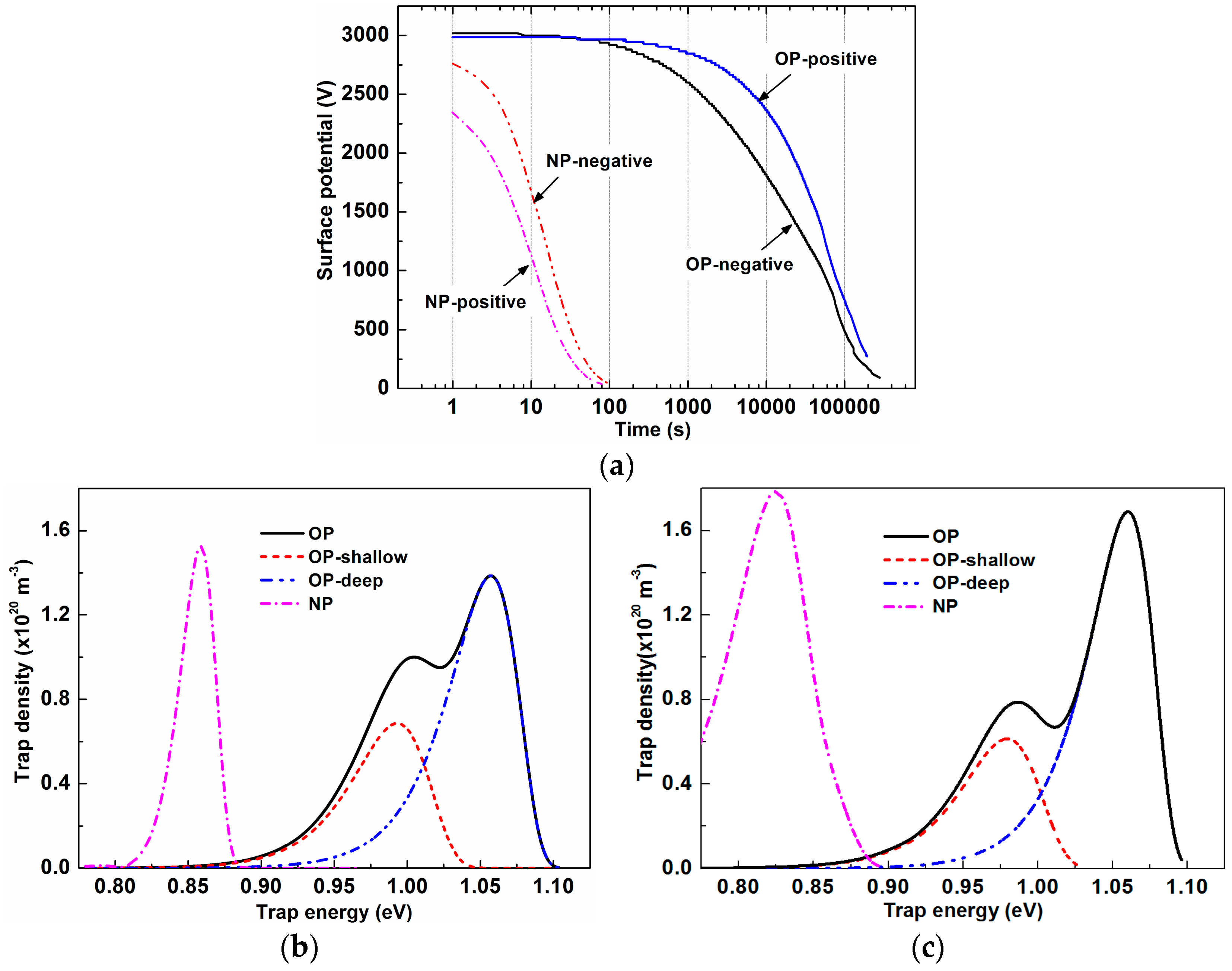
3.4. Isothermal Surface Potential Decay
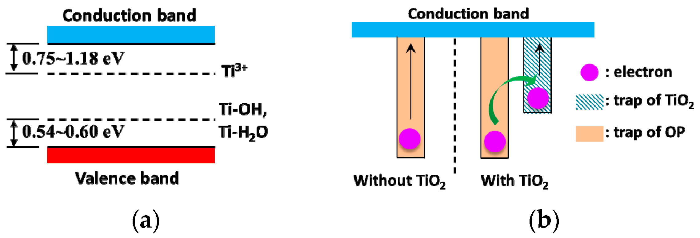
The measured ISPD curves under both negative and positive coronae are given in Figure 6a with the x-axis on a logarithmic scale. The surface potential of NP decayed very quickly, and it decreased to approximately 0 V within 100 seconds no matter whether it was negatively or positively charged. In regard to OP, its surface potential decayed much more slowly, and it was still larger than 500 V after 105 seconds. However, the negative potential varied a little faster than the positive one. Based on the ISPD curves, trap energy and density can be obtained by using [22]:
E t = k T ln ( ν t )
N ( E t ) = ε 0 ε r e l L t ϕ s ( t ) t
where ε0 is vacuum permittivity, εr is the sample’s relative permittivity, l is penetration depth (fixed as 1 μm), L is the thickness of the sample, ϕs is the surface potential, e is electron charge, t is time, and ν is the attempt-to-escape frequency. Calculated trap characteristics are shown in Figure 6b,c, and the relevant parameters are listed in Table 3.
Both electron and hole traps of OP consisted of two peaks that can be divided into a shallow and deep peaks through peak fitting. The center trap energy of deep traps was 0.08 eV higher than that of shallow traps, regardless of trap polarity. For shallow traps, peak density of the holes was 14.5% smaller than that of electrons and 20% larger than electron traps’ peak density for deep ones. The peak density of deep traps was about twice that of shallow traps no matter what polarity it was. TiO2 nanoparticles made a significant difference on trap distributions. There was only one peak for NP’s electron traps as well as hole traps. Though the peak width of the holes was a little wider than that of electrons, NP’s peak density of electrons was similar to that of hole traps, and they were close to those of OP’s sum of deep and shallow traps. However, NP’s trap energies were much lower than those of OP’s shallow traps, not to mention those of deep traps.

4. Discussion

As mentioned before, because of the stable chemical property of cellulose, it is difficult to fabricate fiber with nanoparticles surrounded by cellulose like other solid nano-dielectrics, such as LDPE/MgO nanocomposites [23]. Hence, if one wants to improve the electrical property of OP with nanoparticles, there are generally two possible approaches. The first one is to mix nanoparticles with wood pulp and then stir them before paper sheet preparation [10,14]. The nanoparticles are adsorbed on the surface of fibers, which results in a certain content of nanoparticles in pressboard. The other one is just to make pressboard impregnated with nanofluids [11]. Nanoparticles will transport through the pressboard along the movement of nanofluid, and there will be a deposition of them [24]. No matter which way is used, the main mechanism of nanoparticles addition is adsorption (as well as deposition caused by collision), hence the nanoparticles’ distribution is influenced by the size of the small pores in pressboard and the movement of oil [24,25,26]. The NP was made through the latter way in this paper. Therefore, just the deposition with oil flow was analyzed. The typical transport-deposition model can be described as [27]:
c t = D L 2 c x 2 u c x K dep c
A s t = K dep c ,
and the initial and boundary conditions can be set as:
{ c ( t = 0 , x ) = 0 c ( t , x = d / 2 ) = c ( t , x = d / 2 ) = c 0
where c is the time- and position-dependent nanoparticle density, s is the deposited nanoparticles’ density, d is the pressboard’s thickness, x is position (as illustrated in Figure 3), c0 is the nanoparticles’ density in oil, A is a constant related to dry pressboard’s density and porosity, DL is the longitudinal diffusion coefficient, u is seepage velocity, and Kdep is the deposition coefficient. By solving Equations (5) and (6), nanoparticles’ distribution can be obtained as:
c ( x , t ) = c 0 2 exp [ u ( 0.5 d + x ) 2 D L ( 1 ϕ ) ] erfc ( 0.5 d + x u t ϕ 4 D L t ) + c 0 2 exp [ u ( 0.5 d + x ) 2 D L ( 1 + ϕ ) ] erfc ( 0.5 d + x + u t ϕ 4 D L t ) + c 0 2 exp [ u ( 0.5 d x ) 2 D L ( 1 ϕ ) ] erfc ( 0.5 d x u t ϕ 4 D L t ) + c 0 2 exp [ u ( 0.5 d x ) 2 D L ( 1 + ϕ ) ] erfc ( 0.5 d x + u t ϕ 4 D L t )
where erfc(x) is the residual error function, ϕ = 1 + 4 K dep D L u 2 .
Longitudinal diffusion and deposition coefficients are greatly affected by particle size and seepage velocity [25], but these parameters about TiO2 nanoparticles in NP are absent at present. Choosing u = 0.1 cm/s, DL = 0.06 cm2/s, and Kdep = 0.006 s−1 from other particles to demonstrate the time dependent variation, we got the normalized nanoparticles’ distribution within NP, as shown in Figure 7. Nanoparticles move from the outside to the inside, and the density gradually decreases from outer surface to inner layer at the beginning, which agrees with the result in Table 1. When the time duration is long enough, a uniform distribution of nanoparticles should appear; however, this actually cannot happen, as there are surface and blocking sieving besides deposition, and the subsequent deposition will be influenced [26]. For lack of strong bending force [28], when NP was scoured with pure oil, the TiO2 nanoparticles’ concentration gradient and fluid’s flow made them move from inside to outside, and it was increasingly easier for them to move from the inner layer to the outer surface. Thus, the decrease of the nanoparticles’ density increases with washing duration and depth from inner layer. The time- and position-dependent variation of the nanoparticles’ density means that the nanoparticles cannot stably remain in NP. Therefore, the nanoparticles’ transport and the process of making a stable distribution need further study because nanoparticle density makes a great difference on the electrical property [10,14].
We used anatase TiO2 nanoparticles, the relative permittivity of which can be as high as 48 and dramatically increase in the low frequency region. Hence, there is a peak in the frequency domain spectrum reflecting the polarization of TiO2 nanoparticles, and its relaxation time is 0.08 s. Besides, TiO2 nanoparticles are semi-conductive. Specifically, their conductivity is much larger than that of OP. There is therefore a huge difference on permittivity and conductivity between OP and TiO2 nanoparticles, and though the concentration of TiO2 was just 0.075 vol%, interface polarization was very great. It has been increased approximately three times, as shown in Figure 3b. The TSDC peak at about 315 K corresponds to the interface polarization between oil and fiber [21]. Nevertheless, it has appeared as peak 1 in Figure 5a for OP and peak 2 in Figure 5b for NP. The interface polarization of NP between oil and fiber decreased a little because nanoparticles are deposited on the surface of the fiber. On the other hand, there was a much higher peak at 330 K for NP, and its activation energy was about 0.64 eV. By testing the temperature-dependent permittivity of 18 nm anatase TiO2 nanoparticles, it was found that a peak appears at about 340 K when the frequency is fixed to 96 kHz [29]. According to the absolute-rate theory by Eyring, relaxation time depends on activation energy and temperature:
1 τ = k T h exp ( E a R T )
where h is Planck’s constant—h = 6.63 × 10⁻³⁴ J∙s—and R is gas constant—R = 8.314 J/(mol∙K). Then, the activation energy for TiO2 nanoparticles’ polarization can be obtained as 0.53 eV, which is a little lower than the activation energy measured by TSDC. This is because the interface polarization can actually happen between TiO2 nanoparticles with either fiber or oil. It is induced by their permittivity differences. As a result, its relaxation time is longer and the activation energy is higher. All of those can contribute to the TSDC, and they are so closely related [30] that it is beyond the resolution capability of TSDC. Similarly, the calculated activation energy was found to be 0.67 eV using the relaxation time in Table 3.
On account of this strong interface polarization, the orientation of some dipoles is restricted. As a result, the dipole polarization of NP decreases a little, but its relaxation time increases a lot. Dipole polarization is very fast, and its TSDC peak point temperature is 198 K [21], so part of peak 3 can be seen in Figure 5.
Generally, there inevitably are many oxygen vacancies in anatase-TiO2 nanoparticles. These oxygen vacancies can cause electron localization at original position, which will directly affect the electron structure of TiO2. Unpaired electrons or Ti3+ can be generated consequently, and they act as shallow donor sites 0.75~1.18 eV below the conduction band [31,32]. Meanwhile, though the water content is very limited, there are a certain number of water molecules in NP. H2O molecules can be adsorbed on TiO2 nanoparticles’ surfaces, and some of them can then be dissociated through the forming of bridged hydroxyl groups [33]. Ti-OH and Ti-H2O act as a surface states 0.60 eV and 0.54 eV above the valence band separately [34]. Therefore, the band structure of TiO2 nanoparticles can be illustrated as Figure 8a. Together with Figure 6, it can be seen that the trap energy of TiO2 is much lower than that of OP. From Equation (3), we can get the time for an electron to escape from a trap:
t = 1 ν exp ( E t k T )
The corresponding trap energy-dependent time is displayed in Figure 9. It can be seen that even though the trap energy increases a little, the time for escape is many times longer. It takes about 80 s for an electron to escape from a trap in TiO2 nanoparticles. However, it takes about 1.5 × 10⁶ s for an electron to escape from a trap of 1 eV in OP. After the addition of TiO2 nanoparticles—as the trap energy difference between OP and TiO2 nanoparticles is about 0.4 eV—an electron can move between traps through tunneling or jumping mechanisms [35]. This is awfully fast and only needs 7.5 × 10⁻⁵ s, which can be ignored with respect to the time for escape from a trap in either OP or TiO2 nanoparticles. ISPD results verify that the time is mostly spent on escaping from traps in TiO2 nanoparticles for NP. This means that the electron first transfers from traps in OP to those in TiO2 nanoparticles before escaping in NP (and so does the hole), as illustrated in Figure 8b. As a result, the measured trap energy becomes shallower.

5. Conclusions

The addition of TiO2 nanoparticles restricts the dipole polarization but enhances the interface polarization. Since TiO2 nanoparticles possess a larger permittivity and activation energy, TiO2 nanoparticles’ polarization makes a significant contribution to a new peak of NP’s permittivity spectrum, and the activation energy for interface polarization is increased.
Due to oxygen vacancies, TiO2 nanoparticles offer a springboard for electron and hole transport. They jump into the traps of TiO2 nanoparticles at first, and then they quickly escape from these traps. Hence, the time for escape is greatly shortened, thereby introducing shallow traps.
Because there is a lack of strong bending force between TiO2 nanoparticles and fiber, movement of TiO2 nanoparticles in OP is possible but complex, and their distribution is not stable or controllable. This requires further study.

Author Contributions

Conceptualization, M.H. and C.L.; methodology, M.H.; validation, M.H., Y.L. and C.L.; formal analysis, M.H.; investigation, M.H., Y.Y. and B.S.; resources, Y.L.; data curation, Y.Y. and B.S.; writing—original draft preparation, M.H.; writing—review and editing, Y.Y. and Y.L.; visualization, M.H.; supervision, M.H.; project administration, C.L.; funding acquisition, Y.L. and C.L.

Funding

This research was funded by National Key R&D Program of China, grant number 2017YFB0902704, National Natural Science Foundation of China, grant number 51337003, and China State Key Lab. of Power System, grant number SKLD17KZ01.

Conflicts of Interest

The authors declare no conflict of interest. The funders had no role in the design of the study; in the collection, analyses, or interpretation of data; in the writing of the manuscript, or in the decision to publish the results.

References

  1. Herchl, F.; Marton, K.; Tomčo, L.; Kopčanský, P.; Timko, K.; Koneracká, M.; Kolcunová, I. Breakdown and partial discharges in magnetic liquids. J. Phys.-Condens. Mat. 2008, 20, 1–5. [Google Scholar] [CrossRef] [PubMed]
  2. Segal, V.; Hjortsberg, A.; Rabinovich, A.; Nattrass, D.; Raj, K. AC (60 Hz) and impulse breakdown strength of a colloidal fluid based on transformer oil and magnetite nanoparticles. In Proceedings of the 1998 IEEE International Symposium on Electrical Insulation, Arlington, VA, USA, 7–10 June 1998. [Google Scholar]
  3. Lv, Y.; Du, Y.; Li, C.; Qi, B.; Zhong, Y.; Chen, M. TiO2 nanoparticle induced space charge decay in thermal aged transformer oil. Appl. Phys. Lett. 2013, 102, 132902. [Google Scholar] [CrossRef]
  4. Lv, Y.; Ge, Y.; Wang, L.; Sun, Z.; Zhou, Y.; Huang, M.; Li, C.; Yuan, J.; Qi, B. Effects of nanoparticle materials on prebreakdown and breakdown properties of transformer oil. Appl. Sci. 2018, 8, 601. [Google Scholar] [CrossRef]
  5. Mansour, D.A.; Elsaeed, A.M.; Izzularab, M.A. The role of interfacial zone in dielectric properties of transformer oil-based nanofluids. IEEE Trans. Dielectr. Electr. Insul. 2016, 23, 3364–3372. [Google Scholar] [CrossRef]
  6. Du, B.X.; Li, X.L.; Xiao, M. High thermal conductivity transformer oil filled with BN nanoparticles. IEEE Trans. Dielectr. Electr. Insul. 2015, 22, 851–858. [Google Scholar] [CrossRef]
  7. Jin, H.; Andritsch, T.; Tsekmes, I.A.; Kochetov, R.; Morshuis, P.H.F.; Smit, J.J. Properties of mineral oil based silica nanofluids. IEEE Trans. Dielectr. Electr. Insul. 2014, 21, 1100–1108. [Google Scholar]
  8. Hwang, J.; Zahn, M.; O’Sullivan, F.M.; Pettersson, L.A.A.; Hjortstam, O.; Liu, R. Effects of nanoparticle charging on streamer development in transformer oil-based nanofluids. J. Appl. Phys. 2010, 107, 14310. [Google Scholar] [CrossRef]
  9. Lv, Y.; Ge, Y.; Sun, Z.; Sun, Q.; Huang, M.; Li, C.; Qi, B.; Yuan, J.; Xing, Z. Effect of nanoparticle morphology on pre-breakdown and breakdown properties of insulating oil-based nanofluids. Nanomaterials 2018, 8, 476. [Google Scholar] [CrossRef] [PubMed]
  10. Nikjoo, R.; Taylor, N.; Edin, H.; Hollertz, R.; Wåhlander, M.; Wågberg, L.; Malmström, E. Comparison of oil-impregnated papers with SiO2 and ZnO nanoparticles or high lignin content, for the effect of superimposed impulse voltage on AC surface PD. IEEE Trans. Dielectr. Electr. Insul. 2017, 24, 1726–1734. [Google Scholar] [CrossRef]
  11. Huang, M.; Han, Q.; Lv, Y.; Wang, L.; Shan, B.; Ge, Y.; Qi, B.; Li, C. Effect of nanoparticle shapes on creeping flashover characteristics at the interface of Nanofluid-Impregnated pressboard. IEEE Trans. Dielectr. Electr. Insul. 2018, 25, 1135–1141. [Google Scholar] [CrossRef]
  12. Sun, P.; Sima, W.; Zhang, D.; Jiang, X.; Zhang, H.; Yin, Z. Failure characteristics and mechanism of nano-modified oil-impregnated paper subjected to repeated impulse voltage. Nanomaterials 2018, 8, 504. [Google Scholar] [CrossRef] [PubMed]
  13. Liu, J.; Zhou, L.; Wu, G.; Zhao, Y.; Liu, P.; Peng, Q. Dielectric frequency response of oil-paper composite insulation modified by nanoparticles. IEEE Trans. Dielectr. Electr. Insul. 2012, 19, 510–520. [Google Scholar]
  14. Liao, R.; Wang, J.; Gao, F.; Yuan, Y.; Xu, Z. Effects of aluminum nitride nanoparticles on the space charge behavior of cellulose paper. J. Mater. Sci. 2016, 51, 10701–10713. [Google Scholar] [CrossRef]
  15. Huang, M.; Zhou, Y.; Zhou, Z.; Qi, B. A combined electro-thermal breakdown model for oil-impregnated paper. Energies 2017, 10, 2160. [Google Scholar] [CrossRef]
  16. Li, S.; Zhu, Y.; Min, D.; Chen, G. Space charge modulated electrical breakdown. Sci. Rep. 2016, 6, 32588. [Google Scholar] [CrossRef] [PubMed]
  17. Lv, Y.Z.; Zhou, Y.; Li, C.R.; Ma, K.B.; Wang, Q.; Wang, W.; Zhang, S.N.; Jin, Z.Y. Nanoparticle effects on creeping flashover characteristics of oil/pressboard interface. IEEE Trans. Dielectr. Electr. Insul. 2014, 21, 556–562. [Google Scholar] [CrossRef]
  18. Han, Y.; Li, S.; Min, D. Trap energy distribution in polymeric insulating materials through surface potential decay method. IEEE Trans. Dielectr. Electr. Insul. 2018, 25, 639–648. [Google Scholar] [CrossRef]
  19. Cole, K.S.; Cole, R.H. Dispersion and absorption in dielectrics i. Alternating current characteristics. J. Chem. Phys. 1941, 9, 341–351. [Google Scholar] [CrossRef]
  20. Wu, G.; Zhong, X.; Bao, J. Effect of temperature on dielectric spectrum characteristic of oil-paper insulation. High Volt. Eng. 2015, 41, 4081–4088. [Google Scholar]
  21. Zhu, Y.; Li, S.; Li, T.; Min, D.; Ma, B. Trap parameters analysis of oil-paper insulation by thermally stimulated depolarization current. In Proceedings of the IEEE 11th International Conference on the Properties and Applications of Dielectric Materials, Sydney, NSW, Australia, 19–22 July 2015. [Google Scholar]
  22. Sonnonstine, T.J.; Perlman, M.M. Surface potential decay in insulators with field-dependent mobility and injection efficiency. J. Appl. Phys. 1975, 46, 3975–3981. [Google Scholar] [CrossRef]
  23. Takada, T.; Hayase, Y.; Tanaka, Y.; Okamoto, T. Space charge trapping in electrical potential well caused by permanent and induced dipoles for LDPE/MgO nanocomposite. IEEE Trans. Dielectr. Electr. Insul. 2008, 15, 152–160. [Google Scholar] [CrossRef]
  24. Ahfir, N.; Wang, H.Q.; Benamar, A.; Alem, A.; Massei, N.; Dupont, J.-P. Transport and deposition of suspended particles in saturated porous media: Hydrodynamic effect. Hydrogeol. J. 2007, 15, 659–668. [Google Scholar] [CrossRef]
  25. Benamar, A.; Wang, H.Q.; Ahfir, N.D.; Alem, A. Flow velocity effects on the transport and the deposition rate of suspended particles in a saturated porous medium. Cr. Geosci. 2005, 337, 497–504. [Google Scholar] [CrossRef]
  26. McDowell-Boyer, L.M.; Hunt, J.R.; Sitar, N. Particle transport through porous media. Water Resour. Res. 1986, 22, 1901–1921. [Google Scholar] [CrossRef]
  27. Tufenkji, N. Modeling microbial transport in porous media: Traditional approaches and recent developments. Adv. Water Resour. 2007, 30, 1455–1469. [Google Scholar] [CrossRef]
  28. Segal, V.; Rabinovich, A.; Nattrass, D.; Raj, K.; Nunes, A. Experimental study of magnetic colloidal fluids behavior in power transformers. J. Magn. Magn. Mater. 2000, 215, 513–515. [Google Scholar] [CrossRef]
  29. Wang, G.; Wang, C.; Mou, J.; Zhang, L. Preparation and properties of nanometer-sized TiO2. Chn. J. Mater. Res. 1997, 11, 527–530. [Google Scholar]
  30. Simmons, J.G.; Taylor, G.W.; Tam, M.C. Thermally stimulated currents in semiconductors and insulators having arbitrary trap distributions. Phys. Rev. B 1973, 7, 3714–3719. [Google Scholar] [CrossRef]
  31. Nowotny, M.K.; Sheppard, L.R.; Bak, T.; Nowotny, J. Defect chemistry of titanium dioxide. Application of defect engineering in processing of TiO2-based photocatalysts. J. Phys. Chem. C 2008, 112, 5275–5300. [Google Scholar] [CrossRef]
  32. Pan, X.; Yang, M.Q.; Fu, X.; Zhang, N.; Xu, Y.J. Defective TiO2 with oxygen vacancies: Synthesis, properties and photocatalytic applications. Nanoscale 2013, 5, 3601–3614. [Google Scholar] [CrossRef]
  33. Nadeem, I.M.; Harrison, G.T.; Wilson, A.; Pang, C.L.; Zegenhagen, J.; Thornton, G. Bridging hydroxyls on anatase TiO2(101) by water dissociation in oxygen vacancies. J. Phys. Chem. B 2018, 122, 834–839. [Google Scholar] [CrossRef] [PubMed]
  34. Liu, B.S.; Xin, H.E.; Zhao, X.J. The surface states and the Electron-Hole pair recombination of TiO2 nanopowders. Spectrosc. Spect. Anal. 2006, 26, 208. [Google Scholar]
  35. McLean, F.B.; Boesch, H.E.; McGarrity, J.M. Hole transport and recovery characteristics of SiO2 gate insulators. IEEE Trans. Nucl. Sci. 1976, 23, 1506–1512. [Google Scholar] [CrossRef]
Figure 1. Transmission electron microscopy (TEM) image of TiO2 nanoparticles.
Nanomaterials 09 00174 g001
Figure 2. Schematic diagrams of: (a) The thermally stimulated depolarization current (TSDC) method and (b) the isothermal surface potential decay (ISPD) method.
Nanomaterials 09 00174 g002
Figure 3. Schematic diagrams positions and different layers in impregnated pressboards.
Nanomaterials 09 00174 g003
Figure 4. Frequency domain spectrum of oil-impregnated paper (OP) and nanofluid-impregnated paper (NP): (a) measured permittivity and its fitting curve; (b) their composition of different dielectric relaxation processes.
Nanomaterials 09 00174 g004
Figure 5. Measured TSDC curves and their fitted and separated peaks: (a) peaks of OP; (b) peaks of NP.
Nanomaterials 09 00174 g005
Figure 6. Measured ISPD curves and the corresponding calculated energy distribution: (a) Time dependent surface potential; (b) electron trap energy distribution; (c) hole trap energy distribution.
Nanomaterials 09 00174 g006
Figure 7. Normalized time and position dependent nanoparticles’ density within NP.
Nanomaterials 09 00174 g007
Figure 8. Schematic diagram of electric band structure and electron movement: (a) Band structure of anatase TiO2 with oxygen vacancy; (b) schematic diagram illustrating process of electron escape.
Nanomaterials 09 00174 g008
Figure 9. Time for an electron to escape from a trap with different energies at different temperatures.
Nanomaterials 09 00174 g009
Table 1. Content of titanium element in different layers in impregnated pressboards (Unit: ppm).
SampleInner LayerMiddle LayerOuter Layer
OP0.00.00.0
NP44.5106.0160.0
NP scoured for 168 h31.285.610.2
NP scoured for 336 h16.558.91.17
Table 2. Estimated multiple relaxation Cole-Cole model parameters of OP and NP.
SampleεInterface PolarizationDipole PolarizationTiO2 Polarization
ε1τ1α1ε2τ2α2ε3τ3α3
OP2.230.71262.30.570.0693.1 × 10−40.31
NP2.321.2563.490.670.0689.9 × 10−40.450.510.0840.79
Table 3. Estimated traps parameters of OP and NP.
ParameterNPOP
Shallow TrapsDeep Traps
ElectronHoleElectronHoleElectronHole
Trap energy (eV)0.860.830.980.981.061.06
Trap density (1020 m−3)2.232.420.710.621.401.69

