Abstract
We enhanced the device uniformity for reliable memory performances by increasing the device surface roughness by exposing the HfO2 thin film surface to argon (Ar) plasma. The results showed significant improvements in electrical and synaptic properties, including memory window, linearity, pattern recognition accuracy, and synaptic weight modulations. Furthermore, we proposed a non-identical pulse waveform for further improvement in linearity accuracy. From the simulation results, the Ar plasma processing device using the designed waveform as the input signals significantly improved the off-chip training and inference accuracy, achieving 96.3% training accuracy and 97.1% inference accuracy in only 10 training cycles.
1. Introduction
Big data computing architecture has become more and more popular with the increasing demand of Internet of Things (IoT) [1]. The limited throughput between CPU and memory inhibits the efficiency of big data processing and pushed towards the von Neumann bottleneck [2]. The concept of the artificial neural network (ANN) was developed to achieve efficient computing by mimicking the human brain and neurons [3]. The human brain is a powerful information processing system composed of approximately 1011 neurons and 1015 synapses, which form a massive 3D network that can process and transfer information, consuming low power [4]. The hardware implemented neural systems are one of the promising alternatives for highly efficient learning and pattern recognition ability of massive information with an equivalent approach consuming low power [5]. Recently, nonvolatile-memory (NVM)-based neuromorphic computing has become very popular due to its ability to follow the synaptic plasticity of the biological neurons, which are capable of revolutionizing the computer architecture [6,7]. The definition of synaptic plasticity can be divided into long-term depression (LTD) and long-term potentiation (LTP) [8]. Among the various electrical synapses, resistive random-access memory (RRAM) is one of the potential candidates that can mimic the synaptic behavior by applying electrical pulses. The basic RRAM is composed of two layers of metal electrodes and a transition metal oxide (TMO) as the middle layer. The main principle of operation is that the resistance of TMO varies with the applied bias voltage, and the internal resistance value is used to distinguish the signal. When the electric field exceeds the threshold value, the dielectric layer collapses and changes from high resistance to low resistance, a process called Forming. After Forming, a change in resistance occurs, and the process from high resistance to low resistance is called SET, and conversely, the process from low resistance to high resistance is called RESET. In addition to ease of operation, Resistive Random-Access Memory (RRAM) has numerous desirable features, such as an excellent scaling potential, simple structure, low power consumption, fast switching speed, excellent reliability, and compatibility with the CMOS fabrication process [9,10].
For artificial synaptic applications, high linear conductance change is the most important factor designed to achieve efficient neuromorphic computing [11,12]. Several non-ideal factors of RRAM devices have been reported, including nonlinear weight updating and device variation, which are common in synaptic devices, owing to the intrinsic properties of these devices [13]. For efficient neuromorphic computation, linear conductance change is one of the essential requirements to achieve analog synapse devices. In this work, we aimed to improve the linear potentiation and depression characteristics. To achieve these, we proposed two solutions. First, we applied Ar plasma treatment on the surface of the HfO2 thin film to increase the surface roughness, which could improve the uniformity of the conducting filament. Second, we improved the linear synaptic characteristics by developing a group of non-identical pulse waveforms.
2. Materials and Methods
The schematic configuration of the Al/Ti/HfO2/Pt/Ti/SiO2/Si structures are shown in Figure 1a. The device was fabricated with a crossbar structure on the Si/SiO2 substrate. First, 10 nm/120 nm-thick Ti/Pt (Ti was used as an adhesion layer) were deposited through RF sputtering at room temperature and patterned by UV photolithography flowed by the lift-off process to define the bottom electrode (BE). A 100 nm-thick SiO2 isolation layer was deposited by electron beam evaporation (E-beam). A 5 × 5 µm2 device area was defined by via the hole region using UV–photolithography and was then etched with a reactive ion etching system (RIE) using CF4 to open the device area. Hereafter, a 10 nm thick HfOx resistive switching layer was deposited by an atomic layer deposition (ALD) system at 250 °C with Tetrakis ethylmethylamido hafnium (TEMAHf) and an H2O precursor. Argon (Ar) plasma was applied on the surface of HfOx thin film in an RIE chamber with 50 W power at room temperature. Then, the top electrode (TE) region was patterned by the lithography process and 40 nm/25 nm-thick Ti/Al (Al was served as capping layer) were deposited through RF sputtering at room temperature, respectively, followed by lift-off process where the TE were obtained. Finally, BE pad was defined by photo lithography and etched by RIE using CF4. The TEM image clearly indicates the thickness of each layer in Figure 1b.

Figure 1.
(a) Schematic diagram of the RRAM device with Al/Ti/HfO2/Pt/Ti and a (b) cross-section image of the TEM.
3. Results
To verify switching performances, the HfO2 thin film surface roughness was investigated. Figure 2a shows the atomic force microscopy (AFM) topographic images of the pristine device and Figure 2b shows the plasma-treated device. The root mean square (RMS) value of the plasma-treated HfO2 thin films increased to 0.704 nm compared with that of the pristine HfO2 film of 0.547 nm. The higher surface roughness led to an increase in the effective contact area of the Ti/HfO2 interface, which would lead to the formation of thicker sub-TiOx interfacial layers [14,15]. The formation of a TiOx interfacial layer in the HfOx/Ti interface of the pristine and plasma-treated device was further confirmed by the Ti 2p spectra of the X-ray photoelectron spectroscopy (XPS), as seen in Figure 2c,d. The XPS peak at 454.2 eV confirmed the Ti0 valency of the Ti metallic state and the peak around 455.4 eV defined the Ti2+ valence state to form the TiO and titanium suboxides, while 459.3 eV corresponded to the formation of TiO2 bonding with the Ti4+ valence state at the switching layer and Ti buffer layer interface [16,17]. It is clearly shown that the intensity significantly increased after plasma treatment due to the formation of the thick TiO2 layer. With the increase in sub-TiOx thickness, the oxygen exchange at the interface will be more beneficial, which will result in a higher oxygen vacancy concentration at the interface, and a lower VF with more uniform confinement of conduction filaments (CFs). In order to investigate the effects of Ar plasma on the devices, we first conducted electrical performance measurements and compared the results of the pristine device with the plasma-treated device. The current–voltage (I–V) curves were characterized by an Agilent B1500A parameter analyzer. The BE was grounded, and bias was applied on the TE. Figure 3a,b illustrates the forming curve of the pristine and plasma-treated devices, respectively. It can be observed that the forming voltage (VF) of the plasma-treated device improved to 2 V, which is much lower than the pristine device (VF,pristine = 6.05 V). Moreover, the SET voltage (VSET) value of the plasma-treated devices (VSET,plasma = 1.05 V) also improved in Figure 3c compared with the pristine device (VSET,pristine = 1.2 V), as shown in Figure 3d. For a further analysis regarding the Ar plasma effect on the memory properties of the devices, we performed endurance and retention reliability tests. Both the DC endurance and retention tests were performed at room temperature at a read voltage (Vread) of 0.1 V in both the high-resistance state (HRS) and low-resistance state (LRS). In the DC endurance test in Figure 4a, the ON/OFF ratios of both devices were maintained well after 400 DC duty cycles. In addition, both devices showed a retention time longer than 104 s, and without a significant ON/OFF ratio degradation, as shown in Figure 4b.
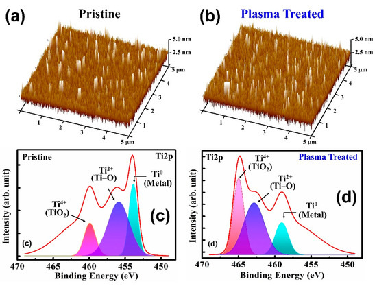
Figure 2.
AFM topographic images of (a) pristine and (b) Ar plasma-treated HfO2 thin films. The Ti 2p spectra at 454.2 eV confirms the Ti0 valence state of the Ti metallic state peak at 459.3 eV, which corresponds to TiO2 bonding with the Ti4+ valence state of (c) the pristine and (d) plasma-treated devices.
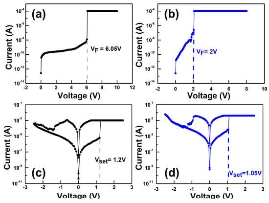
Figure 3.
Forming curves of the (a) pristine and (b) Ar plasma-treated devices. Resistive switching characteristics of the (c) pristine and (d) Ar plasma-treated devices.
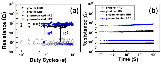
Figure 4.
(a) Endurance of DC switching cycles and (b) retention of the pristine and plasma-treated device.
However, both reliability results indicated enhanced ON/OFF ratio in the plasma-treated device compared with the pristine device. Moreover, we also measured the pulse endurance switching operation (P/E endurance) using a pulse width (PW) of 1 µs. Figure 5 shows the P/E endurance results of the pristine and plasma-treated devices, respectively, with the temperature at a read voltage (Vread) of 0.1 V in both HRS and LRS during the pulse endurance test. Both devices were able to maintain the ON/OFF ratio at 102. However, the plasma-treated device could successfully maintain the ON/OFF ratio after 106 pulse duty cycles compared with the 104 cycles in the pristine device.
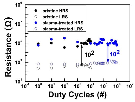
Figure 5.
Endurance of pulse switching cycles of the pristine and plasma-treated devices.
The conduction mechanism was investigated for the fabricated cross-point resistive device. The higher slope value in the ln (I)–ln (V) curve (not shown) expected the possible Ohmic, or space charge limited current conduction (SCLC), in the HRS. The Schottky emission was validated in the HRS from the linear correlation between the ln (I/T2)–V1/2 curve in the low field region (<0.7 V), as shown in Figure 5a. The Schottky barrier height (ΦSB) and the dynamic dielectric constant (εd) were determined from the fitted curve using the following equations [18],
where q is the charge of the electron (1.6 × 10⁻¹⁹ C), T is the absolute temperature (300 K), kB is the Boltzmann constant (1.38 × 10⁻²³ J/K), ε0 is the free space permittivity (8.854 × 10⁻¹⁴ F/cm), and A* is the Richardson–Dushman constant (120 A·cm–2 K2). The effective mass of the electron (m*) in HfO2 was considered to be 0.15 m0 [19]. The Schottky barrier height was calculated to be 0.86 eV at the HfOx/Pt interface using Equation (1), not including the Fermi-level modulation due to the image charge effect in Figure 6a. Some inconsistency may arise between the theoretically and experimentally calibrated ΦSB, as described in previous reports [20,21]. In addition, the εd of the HfOx layer were extracted to 3.53 using Equation (2). This value was verified by obtaining the optical refractive index (n), whose value was 1.87 at 530 nm using the relationship n2 = εd of the ALD deposited HfOx dielectric film near to the prior reported value [22]. The temperature-dependent calibrations ranging from 300 K to 330 K were performed to justify the conduction mechanism. The slope of ln (I/T2)–1/kBT was linearly dependent so as to justify the Schottky thermionic emission in HRS, as shown in Figure 6b. The effective barrier height (Φeff) was calculated in different applied voltages (0.1–0.5 V) using the equation [18]
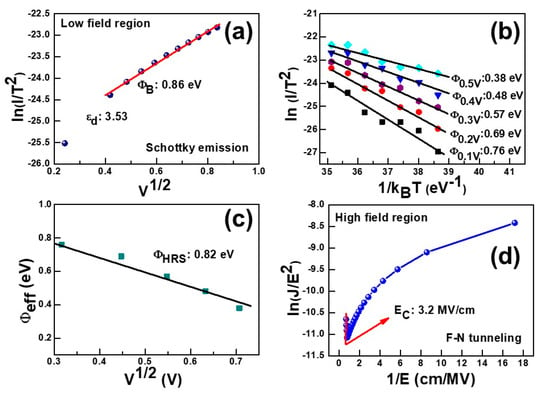
Figure 6.
Charge transportation mechanism exploration by I–V curve fitting at room temperature. (a) Schottky emission [ln(I)–V1/2] occurred at a low field region and (b) temperature dependent (300 K to 330 K) Schottky emission [ln (J/T2)–1/kBT] in the HRS. (c) Schottky barrier height extraction from Φeff–V1/2 plot in the HRS. F-N tunneling conduction occurs at EC > 3 MV/cm. EC is the critical electric field.
Φeff was extracted to 0.82 eV, which is close enough to justify the fitting of the conduction mechanism, as shown in Figure 6c. The F-N tunneling conduction was justified in the HRS currents regions by plotting ln (J/E2) vs. 1/E, where E is the electric field, as shown in the Figure 6d. The tunneling barrier heights (Φb) were estimated from the ln (J/E2) vs. 1/E plots using the following F-N tunneling equation [18],
where S is the slope, mox is the tunneling effective mass of electrons (or holes) in the HfOx layer, and ħ is the reduced Planck’s constant. The linear fitting curve validates the F-N tunneling conduction above the critical electric field (EC) of ≥3 MV/cm [23]. Considering mox = 0.15m0 [19], the value of Φb was calculated to 0.76 eV. Therefore, this is indicates that the HRS current at a higher bias of ≥0.9V is dominated by F-N tunneling.
Next, a non-identical pulse waveform was designed to achieve a better linear conductance change, which could emulate the biological synaptic plasticity of long-term depression (LTD) and long-term potentiation (LTP). Several studies have shown that the biological synaptic plasticity of LTD and LTP can be mimicked as a gradual conductance change response to the programming pulses. The identical pulse waveform is commonly proposed to evaluate the synaptic plasticity of the RRAM synapses [24,25]. However, the conductance change of the potentiation and depression process quickly reaches the saturation state in the preceding few pulses [26]. In this work, we designed specific waveforms to achieve improved linearity in the conductance properties, as shown in Figure 7. Figure 8a shows the synaptic plasticity of the pristine devices that applied 100 consecutive non-identical SET and RESET pulses. The 50 potentiation pulses increased from 1.26 V to 1.6 V with an increasing step voltage of 6 mV. Similarly, 50 depression pulses decreased from −1.3 V to −1.35 V with a decreasing step of 1 mV. In the potentiation process, abrupt conductance transition could be observed in the beginning few pulses. In contrast, the depression (blue dots) process shows a linear conductance change. These results indicate that the dynamics of filament growth and dissolution are not identical. In the beginning of the potentiation process, the CFs were connected to the Ti TE, which resulted in an abrupt increase in conductance change. However, the rest potentiation process showed a slight conductance increasing towards saturation, and this is due to the subsequent increase in the filament diameter [27].
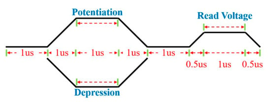
Figure 7.
Pulse waveforms of the potentiation and depression process.
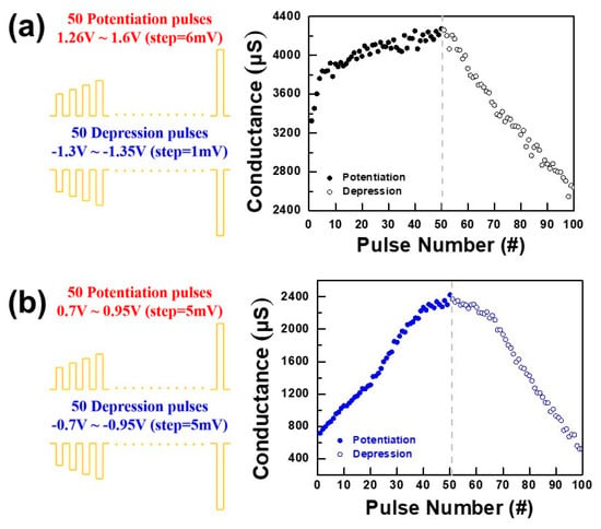
Figure 8.
Synaptic plasticity of (a) pristine and (b) plasma-treated devices.
During the depression process, the decrease in conductance is relatively linear compared with the potentiation process, which indicates the partial/gradual and nearly linear dissolution of CFs.
Figure 8b indicates the synaptic plasticity of the plasma-treated device. The pulse amplitude of both potentiation/depression increased/decreased from 0.7 V to 0.95 V with the increasing/decreasing step voltage of 5 mV. Both the potentiation and depression processes show a linear conductance change, which represents the gradual growth of filaments and, similarly, the linear dissolution of CFs. The results clearly indicate that approximately 50 analog synaptic weight states can be precisely controlled according to potentiation/depression pulse inputs. Moreover, the level of conductance change in potentiation is about 1700 µs, and the value in depression is about 1680 µs, which is almost the same in both processes, which represents precise control in pattern recognition. Moreover, we also investigated the long-term repeatable potentiation and depression cycling endurance of the device applying a total of 10 consecutive non-identical pulses, as shown in Figure 9. The plasma-treated device showed reproducible synaptic characteristics with slight conductance drifting.
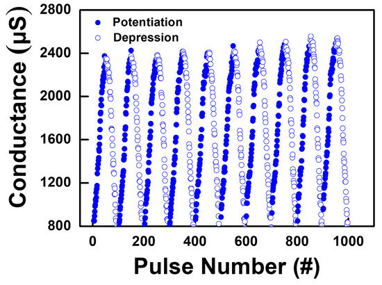
Figure 9.
The potentiation and depression characteristics measured for 10 consecutive non-identical pulses.
Then, to analyze the weight update phenomenon, the nonlinearity (NL) of conductance change was introduced [11]. NL was defined quantitatively as Equation (5),
where GP(n) and GD(n) are the conductance values after the nth potentiation pulse and nth depression pulse, respectively. The conductance values are normalized to the total range from 0 to 1 during the consecutive pulses, and NL is equal to zero for a completely linear update.
Figure 10a,b shows the normalized synaptic plasticity for the potentiation and depression processes under consecutive non-identical pulses for pristine and plasma-treated devices, respectively. The results clearly show that the NL value is 0.39 at n = 25 for the pristine devices, and the NL value is 0.06 at n = 25 for the plasma-treated devices. The NL value of the plasma-treated devices is very close to the ideal linear update. Finally, the effect of the nonlinear weight update of the plasma-treated device on the off-chip training accuracy in a neural network under the designed asymmetric waveform was studied using a binary simulation architecture with the experimentally calibrated conductance variation, as shown in Figure 10b. In the learning algorithm, we considered a neural network system containing a layer of anterior neurons, a layer of posterior neurons, and a crossbar synapse array connecting the anterior and posterior neurons. Figure 11a,c indicates that in the first training cycle, the training accuracy reached 96.1% and the inferred accuracy was 95.5%. Nevertheless, after the tenth training cycle, the training accuracy reached 96.3% and the inferred accuracy was as high as 97.1%, as shown in Figure 11b,d, respectively. The simulation results predicted that the Ar plasma processed device using the designed waveform as the input signal could significantly improve the training and inference accuracy, and only 10 training cycles were needed to achieve 96.3% training accuracy and 97.1% inference accuracy.
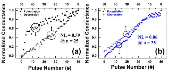
Figure 10.
Normalized synaptic characteristics for the potentiation and depression processes under 50 consecutive non-identical pulses for (a) pristine and (b) plasma-treated devices.
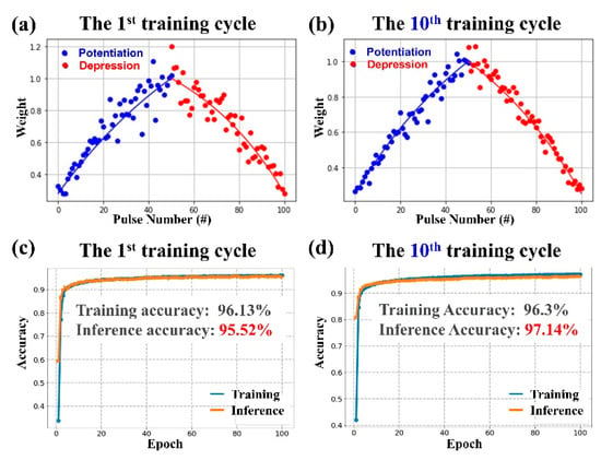
Figure 11.
The simulated weight in (a) the 1st training cycle and (b) the 10th training cycle. The training and inference accuracy in (c) the 1st training cycle and (d) the 10th training cycle.
4. Conclusions
High linearity Si/SiO2/Ti/Pt/HfO2/Ti/Al RRAM devices, by employing Ar plasma treatment on the HfO2 thin film surface, have been demonstrated and calibrated. The plasma-treated devices exhibit a symmetric conductance distribution and pulse height in both the potentiation and depression process compared with the pristine devices. For the plasma-treated devices, the nonlinearity for potentiation and the depression process are very close to ideal linearity. Furthermore, with the designed non-identical pulse waveform, the training and inference accuracy show a significant improvement, and only 10 training cycles need to achieve 96.3% training accuracy and 97.1% inference accuracy.
Author Contributions
K.-J.L. was responsible for the device preparation, characterization, data analysis, modeling discussion, and writing and editing of the manuscript; Y.-C.W. and L.-W.W. were responsible for the data analysis; P.P. and H.-N.L. were responsible for the characterization and modeling discussion; S.-Y.C. and D.L. were responsible for the software analysis; Y.-H.W. was the advisor who monitored the progress and paper editing. All authors have read and agreed to the published version of the manuscript.
Funding
This work was supported in part by the Ministry of Science and Technology of Taiwan under grant MOST 108-2221-E-006-040-MY3.
Institutional Review Board Statement
Not applicable.
Informed Consent Statement
Not applicable.
Data Availability Statement
Not applicable.
Conflicts of Interest
The authors declare no conflict of interest.
References
- Demchenko, Y.; de Laat, C.; Membrey, P. Defining architecture components of the Big Data Ecosystem. In Proceedings of the 2014 International Conference on Collaboration Technologies and Systems (CTS), Minneapolis, MN, USA, 19–23 May 2014. [Google Scholar] [CrossRef]
- Merolla, P.A.; Arthur, J.V.; Alvarez-Icaza, R.; Cassidy, A.S.; Sawada, J.; Akopyan, F.; Jackson, B.L.; Imam, N.; Guo, C.; Nakamura, Y.; et al. A million spiking-neuron integrated circuit with a scalable communication network and interface. Science 2014, 345, 668–673. [Google Scholar] [CrossRef] [PubMed]
- Mead, C. Analog VLSI and Neural Systems; Addison-Wesley: Boston, MA, USA, January 1989; p. 3. [Google Scholar]
- Yu, S.; Gao, B.; Fang, Z.; Yu, H.; Kang, J.; Wong, H.-S.P. A neuromorphic visual system using RRAM synaptic devices with sub-pJ energy and tolerance to variability: Experimental characterization and large-scale modeling. In Proceedings of the 2012 International Electron Devices Meeting, San Francisco, CA, USA, 10–13 December 2012; pp. 10.4.1–10.4.4. [Google Scholar] [CrossRef]
- Woo, J.; Padovani, A.; Moon, K.; Kwak, M.; Larcher, L.; Hwang, H. Linking Conductive Filament Properties and Evolution to Synaptic Behavior of RRAM Devices for Neuromorphic Applications. IEEE Electron Device Lett. 2017, 38, 1220–1223. [Google Scholar] [CrossRef]
- Ohno, T.; Hasegawa, T.; Tsuruoka, T.; Terabe, K.; Gimzewski, J.K.; Aono, M. Short-term plasticity and long-term potentiation mimicked in single inorganic synapses. Nat. Mater. 2011, 10, 591–595. [Google Scholar] [CrossRef] [PubMed]
- Thunder, S.; Pal, P.; Wang, Y.-H.; Huang, P.-T. Ultra Low Power 3D-Embedded Convolutional Neural Network Cube Based on α-IGZO Nanosheet and Bi-Layer Resistive Memory. In Proceedings of the 2021 International Conference on IC Design and Technology (ICICDT), Dresden, Germany, 15–17 September 2021. [Google Scholar] [CrossRef]
- Hughes, J.R. Post-tetanic potentiation. Physiol. Rev. 1958, 38, 91–113. [Google Scholar] [CrossRef] [PubMed]
- Ielmini, D.; Wong, H.-S.P. In-Memory Computing with Resistive Switching Devices. Nat. Electron. 2018, 1, 333–343. [Google Scholar] [CrossRef]
- Pal, P.; Thunder, S.; Tsai, M.-J.; Huang, P.-T.; Wang, Y.H. Benchmarking the Performance of Heterogeneous Stacked RRAM with CFETSRAM and MRAM for Deep Neural Network Application Amidst Variation and Noise. In Proceedings of the 2021 International Symposium on VLSI Technology, Systems and Applications (VLSI-TSA), Hsinchu, Taiwan, 19–22 April 2021; pp. 1–2. [Google Scholar] [CrossRef]
- Wang, I.-T.; Chang, C.-C.; Chiu, L.-W.; Chou, T.; Hou, T.-H. 3D Ta/TaOx/TiO2/Ti synaptic array and linearity tuning of weight update for hardware neural network applications. Nanotechnology 2016, 27, 365204. [Google Scholar] [CrossRef] [PubMed]
- Chandrasekaran, S.; Simanjuntak, F.M.; Panda, D.; Tseng, T.Y. Enhanced synaptic linearity in ZnO-based invisible memristive synapse by introducing double pulsing scheme. IEEE Trans. Electron Devices 2019, 66, 4722–4726. [Google Scholar] [CrossRef]
- Chen, P.-Y.; Lin, B.; Wang, I.-T.; Hou, T.-H.; Ye, J.; Vrudhula, S.; Seo, J.-S.; Cao, Y.; Yu, S. Mitigating effects of non-ideal synaptic device characteristics for on-chip learning. In Proceedings of the 2015 IEEE/ACM International Conference on Computer-Aided Design (ICCAD), Austin, TX, USA, 2–6 November 2015. [Google Scholar] [CrossRef]
- Kim, H.-D.; Yun, M.J.; Hong, S.M.; Park, J.H.; Jeon, D.S.; Kim, T.G. Impact of roughness of bottom electrodes on the resistive switching properties of platinum/nickel nitride/nickel 1 × 1 crossbar array resistive random access memory cells. Microelectron. Eng. 2014, 126, 169–172. [Google Scholar] [CrossRef]
- Cavallini, M.; Hemmatian, Z.; Riminucci, A.; Prezioso, M.; Morandi, V.; Murgia, M. Regenerable Resistive Switching in Silicon Oxide Based Nanojunctions. Adv. Mater. 2012, 24, 1197–1201. [Google Scholar] [CrossRef] [PubMed]
- Peng, W.-C.; Chen, Y.-C.; He, J.-L.; Ou, S.-L.; Horng, R.-H.; Wuu, D.-S. Tunability of p- and n-channel TiOx thin film transistors. Sci. Rep. 2018, 8, 9255. [Google Scholar] [CrossRef] [PubMed]
- Pal, P.; Mazumder, S.; Huang, C.-W.; Lu, D.D.; Wang, Y.-H. Impact of the Barrier Layer on the High Thermal and Mechanical Stability of a Flexible Resistive Memory in a Neural Network Application. ACS Appl. Electron. Mater. 2022, 4, 1072–1081. [Google Scholar] [CrossRef]
- Sze, S.M.; Ng, K.K. Physics of Semiconductor Devices, 3rd ed.; John Wiley & Sons: Hoboken, NJ, USA, 2006. [Google Scholar] [CrossRef]
- Monaghan, S.; Hurley, P.; Cherkaoui, K.; Negara, M.; Schenk, A. Determination of electron effective mass and electron affinity in HfO2 using MOS and MOSFET structures. Solid-State Electron. 2009, 53, 438–444. [Google Scholar] [CrossRef]
- Yoon, J.H.; Song, S.J.; Yoo, I.-H.; Seok, J.Y.; Yoon, K.J.; Kwon, D.E.; Park, T.H.; Hwang, C.S. Highly Uniform, Electroforming-Free, and Self-Rectifying Resistive Memory in the Pt/Ta2O5/HfO2-x/TiN Structure. Adv. Funct. Mater. 2014, 24, 5086–5095. [Google Scholar] [CrossRef]
- Pal, P.; Lee, K.-J.; Thunder, S.; De, S.; Huang, P.-T.; Kampfe, T.; Wang, Y.-H. Bending Resistant Multi-bit Memristor for Flexible Precision Inference Engine Application. IEEE Trans. Electron Devices 2022, 69, 4737–4743. [Google Scholar] [CrossRef]
- Wei, Y.; Xu, Q.; Wang, Z.; Liu, Z.; Pan, F.; Zhang, Q.; Wang, J. Growth properties and optical properties for HfO2 thin films deposited by atomic layer deposition. J. Alloys Compd. 2018, 735, 1422–1426. [Google Scholar] [CrossRef]
- Samanta, S.; Rahaman, S.Z.; Roy, A.; Jana, S.; Chakrabarti, S.; Panja, R.; Roy, S.; Dutta, M.; Ginnaram, S.; Prakash, A.; et al. Understanding of multi-level resistive switching mechanism in GeOx through redox reaction in H2O2/sarcosine prostate cancer biomarker detection. Sci. Rep. 2017, 7, 1–12. [Google Scholar] [CrossRef] [PubMed]
- Calka, P.; Sowinska, M.; Bertaud, T.; Walczyk, D.; Dabrowski, J.; Zaumseil, P.; Walczyk, C.; Gloskovskii, A.; Cartoixà, X.; Suñé, J.; et al. Engineering of the Chemical Reactivity of the Ti/HfO2 Interface for RRAM: Experiment and Theory. ACS Appl. Mater. Interfaces 2014, 6, 5056–5060. [Google Scholar] [CrossRef] [PubMed]
- Woo, J.; Moon, K.; Song, J.; Lee, S.; Kwak, M.; Park, J.; Hwang, H. Improved synaptic behavior under identical pulses using AlOx/HfO2 bilayer RRAM array for neuromorphic systems. IEEE Electron Device Lett. 2016, 37, 994–997. [Google Scholar] [CrossRef]
- Ku, B.; Abbas, Y.; Kim, S.; Sokolov, A.S.; Jeon, Y.-R.; Choi, C. Improved resistive switching and synaptic characteristics using Ar plasma irradiation on the Ti/HfO2 interface. J. Alloys Compd. 2019, 797, 277–283. [Google Scholar] [CrossRef]
- Hasegawa, T.; Ohno, T.; Terabe, K.; Tsuruoka, T.; Nakayama, T.; Gimzewski, J.K.; Aono, M. Learning abilities achieved by a single solid-state atomic switch. Adv. Mater. 2010, 22, 1831–1834. [Google Scholar] [CrossRef] [PubMed]
Publisher’s Note: MDPI stays neutral with regard to jurisdictional claims in published maps and institutional affiliations. |
© 2022 by the authors. Licensee MDPI, Basel, Switzerland. This article is an open access article distributed under the terms and conditions of the Creative Commons Attribution (CC BY) license (https://creativecommons.org/licenses/by/4.0/).