Abstract
Graphene field-effect transistors (GFETs) exhibit unique switch and sensing features. In this article, GFETs are investigated within the tight-binding formalism, including quantum capacitance correction, where the graphene ribbons with reconstructed armchair edges are mapped into a set of independent dual channels through a unitary transformation. A new transfer matrix method is further developed to analyze the electron transport in each dual channel under a back gate voltage, while the electronic density of states of graphene ribbons with transversal dislocations are calculated using the retarded Green’s function and a novel real-space renormalization method. The Landauer electrical conductance obtained from these transfer matrices was confirmed by the Kubo–Greenwood formula, and the numerical results for the limiting cases were verified on the basis of analytical results. Finally, the size- and gate-voltage-dependent source-drain currents in GFETs are calculated, whose results are compared with the experimental data.
1. Introduction
Graphene is a one-atom-thick planar sheet of carbon atoms in a honeycomb structure, whose free-standing monolayer was isolated and characterized for the first time in 2004 by Andre Geim and Konstantin Novoselov [1]. This material possesses outstanding properties such as high specific surface area [2], very high carrier mobility with null effective mass [3], huge thermal conductivity, and giant Young’s modulus [4], making it an ideal candidate for a wide range of applications [5].
When the semiconductor layer of a traditional metal–oxide–semiconductor field-effect transistor (MOSFET) is replaced by a graphene sheet, it is called as graphene field-effect transistor (GFET), whose source-drain current is extremely sensitive to the adsorbed molecules, and it is employable for use in gas and bio sensing [6,7,8]. Moreover, GFET constitutes a central component of far-infrared radiation and terahertz devices [9] since graphene exhibits a quick optical response based on high carrier mobility [10]. In addition, the graphene nanoribbon field-effect transistor (GNRFET) presents an elevated ratio around the threshold voltage compared to the conventional Si-based CMOS [11]. Among possible disadvantages of GFETs, there are difficulties in fabricating wafer-sized high-quality graphene, as well as the apparent degradation of carrier mobility when it is placed over an oxide [12].
Additionally, GFET has a singular capacitor behavior, since the graphene ribbon, being one of the parallel plates, possesses a very low charge density around the Dirac point, which may induce large variations in its chemical potential when a small amount of electric charge is introduced into the capacitor. This fact could significantly increase the potential difference between the back gate and the graphene, because it is equal to the difference between the chemical potentials at each plate. Such small quantities of charge generating a large potential difference lead to a lower capacitance compared to geometric or classic ones () obtained using ideal metal plates. Hence, the capacitance of GFET can be calculated by including a so-called quantum capacitance () through [13].
On the theoretical side, GFETs can be modeled at the atomic scale by means of first-principle or semiempirical methods. For example, N/B/P co-doped seven-atom-wide armchair GNRFET was analyzed by using the density functional theory (DFT) [14], while ten-atom-width GNRFET has been studied by self-consistently solving Schrödinger–Poison equations within the tight-binding formalism [15]. Recently, mesoscopic GFETs have been extensively investigated for the detection of micron-scale biomolecules [16] and their graphene ribbons contain several billions of atoms, which impede atomic-scale first-principle modeling. In addition, such graphene ribbons usually possess numerous structural defects, which requires an innovative real-space approach [17].
In this article, the source-drain current () in mesoscopic GFETs is studied by means of an independent dual-channel method that transforms the graphene ribbon with edge reconstruction defects and transversal dislocations into a set of double chains with first and second neighbor interactions within the tight-binding formalism. The electrical conductance and electronic density of states in these double chains or dual channels connected to two semi-infinite periodic leads at their ends are further addressed by means of a new transfer matrix method within the Landauer formalism and a novel real-space renormalization procedure based on the retarded Green’s function, respectively. The theoretical , as a function of the gate voltage, is compared with experimental data obtained from GFETs of different lengths.
2. The Model
In GFETs, an extra carrier density () can be induced in graphene ribbon by the application of a gate voltage (), which is related to the chemical potentials of graphene () and of back gate metal () through . Figure 1 shows a schematic representation of (Figure 1a) top and (Figure 1b,c) side views of a backgated GFET with energy band diagrams for (b) and (c) , where the diminution of due to is denoted as . Hence, we have:
which is equivalent to , since , , and with or at the Dirac point in our case [18].
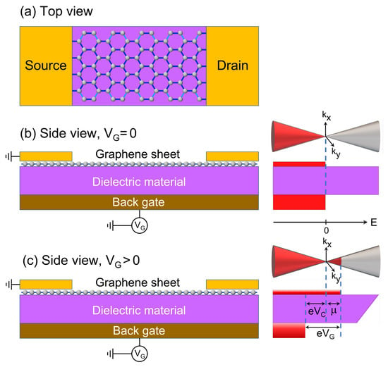
Figure 1.
Schematic representations of (a) top and (b,c) side views of a backgated GFET with Dirac cones and energy band diagrams for (b) VG = 0 and (c) VG > 0, where eVG = eVC + µ being µ the chemical potential of graphene ribbon with respect to the Dirac point.
In general, the capacitance per unit of area (C) of an ideal parallel-plate capacitor with a dielectric material of thickness d and a relative permittivity is in units of MKS [19], where is the vacuum permittivity, is the electric charge per unit of area in the capacitor and is the potential difference between the parallel plates. Hence:
where e is the magnitude of the electron charge.
Let us consider an armchair-edged graphene ribbon with an even number of atoms (2W) in each transversal zig-zag line, as illustrated in Figure 2a. This ribbon of width and length is found in a backgated GFET, where W and L are integer numbers, Å and Å are bond lengths between interior atoms and between the edge and next-edge atoms, respectively denoted by blue and thick blue lines in Figure 2a. This variation in interatomic distance is originated from the edge reconstruction of graphene ribbons [20]. The single-electron tight-binding Hamiltonian (H) of this graphene ribbon with null on-site energies can be written as
where is the Wannier function at site , t is the hopping integral of pristine graphene sheet and is that between the edge and next-edge atoms in a graphene ribbon with edge reconstructions [20] and with is the hopping integral between transversal zig-zag lines l and , representing possible transversal dislocations when .
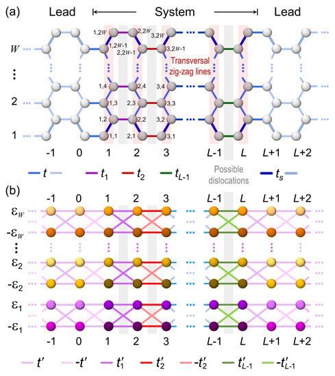
Figure 2.
Sketch of (a) a graphene ribbon of width W and length L with hopping integrals t, and , being , connected to two semi-infinite periodic leads (light grey spheres) and (b) double chains obtained from the independent dual-channel method (Appendix A) with hopping integrals , and on-site energies being Red highlight and gray zones respectively indicate zig-zag lines and possible transversal dislocations.
There is a unitary transformation discussed in Appendix A that converts the Hamiltonian (3), including the edge reconstruction defects, into a set of W independent dual channels, whose Hamiltonian contains hopping integrals , with and on-site energies with which are eigenvalues obtained from the Hamiltonian of an arbitrary transversal zig-zag line in Figure 2.
The extra carrier density () induced by in the graphene ribbon can be calculated by [21]
where
is the density of states with the retarded Green’s function and η the imaginary part of energy [22]. Combining Equations (2) and (4), can be determined as the solution of following self-consistent equation,
On the other hand, the source-drain current () of GFETs at temperature T is given by [23]
where is the source-drain voltage and
is the electrical conductance of graphene ribbon at chemical potential μ within the Landauer formalism. In Equation (8), is the Fermi–Dirac distribution, is the conductance quantum, is the carrier transmittance of graphene ribbon, and at zero temperature we have [24]
By means of the independent dual-channel method presented in Appendix A, an armchair-edged graphene ribbon can be transformed into a set of double chains or dual channels (see Figure 2) and then
where is the carrier transmittance along the j-th dual channel. We further developed a new transfer matrix method to calculate , which is thoroughly presented in Appendix B, and the result can be written as
where are elements of the total transfer matrix, and are respectively initial wavefunction amplitudes at the up and down channels, both from the j-th dual channel (see Appendix B).
One of structural defects commonly observed in graphene ribbons is linear dislocation [25,26], because its presence slightly alters the free energy but may significantly modify the carrier transport. In this article, we consider a distribution of transversal dislocations following the Rudin–Shapiro (RS) sequence, which constitutes one of the closest aperiodic arrays to the random distribution [27]. A Rudin–Shapiro lattice with bond disorder can be built by using four kinds of dislocation hopping integrals , respectively denoted by letters A, B, C or D, whose positions along the ribbon are ordered by the substitution rules [28]
or by the addition rules expressed as
where the symbol represents the concatenation operation and is the α-type RS sequence of generation k with . As a consequence, a graphene ribbon based on has transversal zig-zag lines. To have a limited number of dislocations, let us introduce dilute RS lattices, which are built by using periodic segments to construct the RS lattice until generation and a single transversal dislocation is placed at the initial of next generation m. For example, when , , , and , where P denotes a periodic RS sequence with hopping integral t connecting all transversal zig-zag lines. A detailed discussion of this dilute RS lattice and the real-space renormalization method can be found in Appendix C.
Another quantity that should be considered for determining the electrical conductance is the contact resistance between the graphene ribbon and periodic leads. In the diffusive regime, the total resistance () can be written as [29,30]
where is the electrical resistance of a graphene ribbon with length and width , being that of a square graphene sheet, and is the specific contact resistance in units of μm, which can be experimentally determined by the transfer length method [31]. Hence, the total conductance defined as can be calculated from Equation (14) through
where is the conductance of graphene ribbon. For a uniform sample, the electrical resistance of a p-micron segment, R( μm), should be times of R( μm) obtained from a q micrometer portion. Therefore, Equation (15) can be rewritten as
where . This equation will be used in the length variation analysis.
3. Results
The electronic density of states, , of a graphene ribbon built by W dual channels based on an α-type dilute RS sequence of generation k can be written as [22]
where is the number of sites in each dual channel and is the l-th diagonal element of the retarded Green’s function evaluated at . The of the j-th dual channel can be rewritten as
where are the renormalization coefficients and with are matrix elements of the Green’s function corresponding to the left up (L), left down (L), right up (R) and right down (R) sites of the renormalized four-site j-th dual channel, which constitutes the basic element of the real-space renormalization method presented in Appendix C.
Figure 3 shows the electronic density of states (DOS) and the electrical conductance (g) at zero temperature in units of the conductance quantum obtained from Equation (9) as functions of the chemical potential (μ) for free-standing graphene ribbons without dislocations, whose widths are (red lines), (dark yellow lines) and (blue lines) as well as an arbitrary length of L transversal zig-zag lines. All the ribbons studied in this article are connected to two semi-infinite periodic leads at their ends, as illustrated in Figure 2a, while a surface hopping integral due to the edge reconstruction and an imaginary part of energy are also included.
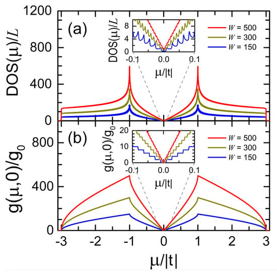
Figure 3.
(a) Electronic density of states (DOS) and (b) electrical conductance (g) at in units of versus the chemical potential (μ) for graphene ribbons of (red lines), (dark yellow lines), and (blue lines) with an arbitrary length of L transversal zig-zag lines and hopping integrals of t and .
Observe the Van Hove singularities in the inset of Figure 3a, which are located at the band limits of each dual channel. The DOS spectra of Figure 3a can be analytically verified through [32]
where and can be obtained from Equation (A9) in Appendix B. Note also the quantized conductance spectra in the inset of Figure 3b and the maximum values of around in Figure 3b is equal to the number of dual channels (W).
To analyze the electrical conductance (g) of GFETs, we first self-consistently calculate from Equation (6) for a given and then, the chemical potential μ and can be respectively determined using Equations (1) and (8). Figure 4 shows the electrical conductance (g) at (blue lines) and at (red lines) versus the gate voltage () for GFETs of , i.e., dual channels, and zig-zag lines without dislocations, whose capacitances per unit area are (a) and (b) . Note the quantized conductance spectra for , in contrast to the smoothed ones when T increases, as well as the growth of conductance with the capacitance.
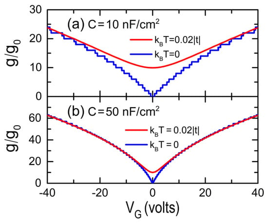
Figure 4.
Normalized electrical conductance (g) by the conductance quantum at and at as a function of the gate voltage for GFETs with (a) and (b) , whose dimensions are and zig-zag lines without dislocations.
In Figure 5, the electrical conductance () at is plotted as a function of both the back gate voltage and the dislocation hopping integral for the same graphene ribbon of Figure 4 except by the value of maintaining . This ribbon contains 72 A-type transversal dislocation lines obtained from a A-type dilute RS lattice with and dislocations introduced from generation , and it is placed on a GFET with a capacitance per unit area . Observe the V-shaped dependence between g and , even for , and this dependence can be noted from Figure 3b, since modifies the value of chemical potential μ, as shown in Figure 1c.
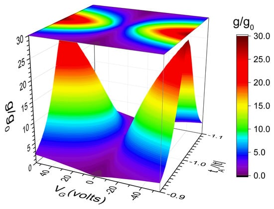
Figure 5.
Electrical conductance (g) at as a function of gate voltage () and dislocation hopping integral for the same GFET of Figure 4a except by 72 A-type transversal dislocations lines placed following the dilute RS sequence with and .
Figure 6 shows the electrical conductance (g) at (Figure 6a) and (Figure 6b) with [20] as functions of the gate voltage () for GFETs of (i.e., dual channels) and (red lines), (green lines), and (blue lines), respectively corresponding to generations , 11 and 12 of A-type dilute RS sequences with dislocations introduced from generation , hopping integrals , and , where the capacitance per unit area of GFET is .
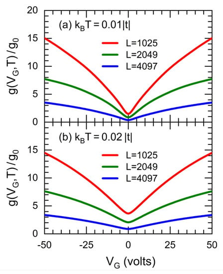
Figure 6.
Conductance (g) at (a) and (b) as functions of the gate voltage () for GFETs with dislocations and a capacitance , (i.e., dual channels) and (red lines), (green lines), and (blue lines), whose hopping integrals are , and .
The results reveal a more emphasized V-shaped conductance behavior at lower temperatures, while the electrical conductance diminishes with increasing RS generation, being almost inversely proportional to the GFET length, in accordance with the Ohm’s law as well as the length variation measurements carried out in GFET [33].
Finally, let us consider a specific GFET [29] built by an armchair-edged graphene ribbon placed on a substrate of silicon dioxide (SiO2) of thickness , i.e., a geometric capacitance per unit area of . We first calculated the electrical conductance g of a graphene ribbon having a width of dual channels () and a length of zig-zag lines ( corresponding to generation 12 of the RS sequence), which contains 1024 transversal dislocation lines from a A-type dilute RS lattice with and hopping integrals , , , and as in Figure 6, while the analysis of system length () effects on the conductance was carried out by means of Equation (16). Additionally, the contact resistance described in ref. [29] is included in the total conductance using Equation (15). In Figure 7, we present the source-drain current () at as a function of the gate voltage and graphene ribbon length () for the considered GFET with a source-drain voltage of , where (red spheres) was obtained from and Equation (16) with and .
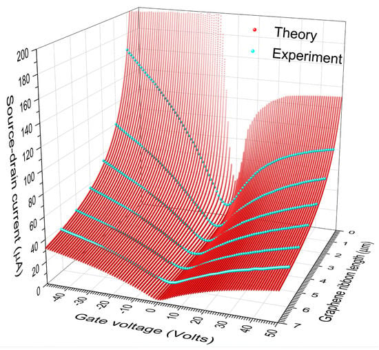
Figure 7.
Theoretical source-drain current (red spheres) versus gate voltage () and graphene ribbon length () for a GFET of a width and a capacitance per unit area , in comparison with experimental data (cyan spheres) reported from Ref. [28] for .
The accordance between the theoretical () and experimental () source-drain currents can be quantified by means of the standard deviation (σ), given by
where is the j-th analyzed gate voltage and are digitalized experimental data (cyan spheres in Figure 7) from reference [29] with . The resulting σ for graphene ribbons of are respectively 3.4423, 3.0119, 2.5801, 2.7210, 1.9327 and 1.4795 μA.
Note in Figure 7 the asymmetry of values with respect to , whose magnitude diminishes as the ribbon length increases. This asymmetry is derived from that of the contact-resistance () spectrum in ref. [29], which is probably related to the slight doping of the used graphene ribbon [30]. In fact, the contribution of to diminishes as the resistance of graphene ribbon (R) grows [see Equation (15)], while R in turn increases with the ribbon length. Therefore, the asymmetry of respect to should decrease as the ribbon length grows.
4. Conclusions
The correlation between source-drain current and gate voltage in graphene field-effect transistors (GFETs) is investigated by means of an atomic-scale tight-binding model, where mesoscopic graphene ribbons with edge reconstruction defects and transversal dislocations are addressed by an independent dual-channel transformation, which converts armchair-edged graphene ribbons into a set of independent dual channels.
The electronic transport was studied within the Landauer formalism, and a new transfer matrix method has been further developed for each dual channel with nearest- and next-nearest-neighbor interactions, including aperiodically placed dislocations following a dilute Rudin–Shapiro (RS) sequence, which is one of the closest aperiodic arrangements to the random distribution. The Landauer conductance was confirmed by that obtained from the Kubo–Greenwood formula (see Appendix B), while the density of states from the Green’s function has been verified by analytical solutions of Equation (19) for the case without dislocations.
Quantized electrical conductance spectra are observed even in presence of edge reconstruction defects along mesoscopic graphene ribbons without dislocations, whose maximum value corresponds to the number of dual channels, while the multi-step behavior is softened at finite temperatures. In addition, the back gate voltage () creates a shift of the chemical potential in graphene ribbons, which produces a V-shape correlation between the source-drain current () and originated from the V-shape DOS spectrum of graphene around the Dirac point. Finally, the realistic calculation of reveals an excellent agreement between the theoretical prediction from a single set of parameters and multiple experimental data obtained from GFETs of six different lengths [29].
The approach of independent dual-channel plus renormalization method presented in this article can be used to study biosensor devices based on GFETs by considering adsorbed molecules as Fano impurities [34]. This study is currently in process.
Author Contributions
Conceptualization, F.S., V.S. and C.W.; methodology, F.S., V.S. and C.W; software, F.S., V.S. and C.W; validation, F.S., V.S. and C.W.; formal analysis, F.S., V.S. and C.W; investigation, F.S., V.S. and C.W; resources, F.S., V.S. and C.W; data curation, F.S., V.S. and C.W; writing—original draft preparation, F.S., V.S. and C.W; writing—review and editing, F.S., V.S. and C.W; visualization, F.S., V.S. and C.W; supervision, F.S., V.S. and C.W; project administration, F.S., V.S. and C.W; funding acquisition, V.S. and C.W All authors have read and agreed to the published version of the manuscript.
Funding
This work has been partially supported by the Consejo Nacional de Ciencia y Tecnología of Mexico (CONACyT) through grant 252943 and by the National Autonomous University of Mexico through projects PAPIIT-IN110020 and PAPIIT-IN112522. The computations were performed at Miztli of DGTIC-UNAM.
Institutional Review Board Statement
Not applicable.
Informed Consent Statement
Not applicable.
Data Availability Statement
Data sharing not applicable.
Acknowledgments
The technical assistance of Alberto López (R.I.P.), Alejandro Pompa, Cain González, Silvia E. Frausto, and Yolanda Flores are fully appreciated. F.S. acknowledges the postdoctoral fellowship from CONACyT.
Conflicts of Interest
The authors declare no conflict of interest.
Appendix A. Independent Dual-Channel Method
Let us consider an armchair-edged graphene ribbon with a width of four atoms and an arbitrary length of L transversal zig-zag lines described by Hamiltonian (3), which in the matrix form following the atom numbering of Figure A1a can be written as
where
being t and the interior- and surface-hopping integrals, whose difference is originated from the edge reconstruction of graphene ribbons [20]. In Equation (A2), with are hopping integrals that connect zig-zag lines and through them transverse dislocations can be introduced. The eigenvalues of matrix are and .
Let us further introduce a unitary transformation given by
where being .
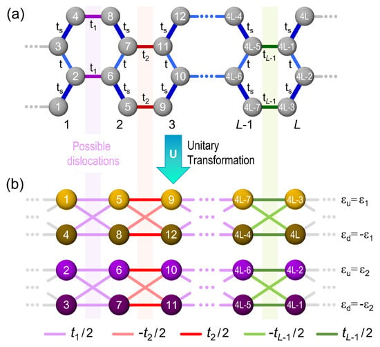
Figure A1.
(a) Sketch of an armchair-edged graphene nanoribbon with a width of 4 atoms, arbitrary length L, null on-site energies, hopping integrals t (light blue lines), (violet lines), (red lines), (green lines) and (thick blue lines); (b) by applying a unitary transformation U, the nanoribbon (a) becomes into two independent dual-channels with on-site energies ( and ) and hopping integrals (light violet lines), (light red lines) and (light green lines). Numbers inside spheres denote the positions in Hamiltonian matrices (A1) and (A4) respectively before and after the application of U.
Applying this transformation (U) to H we obtain
where
being with .
Hence, for a graphene ribbon with a width of four atoms and arbitrary length L, Hamiltonian can be visualized as two independent dual channels, as illustrated in Figure A1b with on-site energies and hopping integrals , and . It is worth mentioning that the independent dual-channel method presented in this appendix includes the ribbon edge reconstruction, and a particular case of this method can be found in reference [35] for .
Appendix B. Transfer Matrix Method for Dual Channels
Let us consider a dual channel or double chain obtained from the unitary transformation of Appendix A, as illustrated in Figure A2, whose Hamiltonian can be written as
where is the hopping integral between transversal lines l and , and are respectively the Wannier functions at the up and down sites of transversal line l. In contrast, there is no variation in hopping integrals in periodic leads. Moreover, the system possesses an odd number L of transversal lines, since a Rudin–Shapiro (RS) distribution of bonds is considered.

Figure A2.
Dual-channel system of 2L sites with hopping integrals connected to two semi-infinite periodic leads with where the on-site energies are and . Green dashed lines indicate unit cells whose wavefunction amplitudes without phases are denoted on the spheres.
In these periodic dual-channel leads, the unit cell of length a is constituted by four sites and the electronic wavefunction with wavenumber k can be written as
where m is the index of unit cells. The stationary Schrödinger equation leads to
whose eigenvalues or dispersion relations are
where a is the lattice constant indicated in Figure A2. These four dispersion relations of (A9) are plotted in Figure A3 for , and in the first dual channel analyzed in Appendix A.
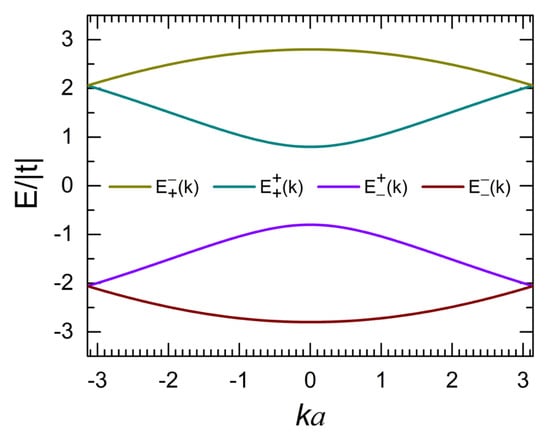
Figure A3.
Dispersion relations and versus ka for periodic dual-channel leads with and .
Wavefunction amplitudes and for obtained from Equation (A8) are summarized in Table A1 for each energy band, shown for example in Figure A3.

Table A1.
Amplitudes and in periodic dual-channel leads with and .
Table A1.
Amplitudes and in periodic dual-channel leads with and .
| Energy Band | u0 (k) | d0 (k) | u1 (k) | d1 (k) |
|---|---|---|---|---|
where and .
On the other hand, for a dual-channel system of L transversal lines connected to two periodic leads represented by lines zero and , the wavefunction of both system and leads can be written as
and then, the stationary Schrödinger equation from Hamiltonian (A6) is given by
where , and . Equations (A11) can be rewritten in matrix form as
where , () and () are respectively wavefunction coefficients at the up (down) site of transversal lines zero and ,
and the total transfer matrix including connections to periodic leads and .
For the case of an electronic plane wave incident from the left lead of Figure A1, the scattered ones by the system are a reflected wave moving to the left and another transmitted one going to the right. Hence, the wavefunction coefficients at transversal line zero and line can be respectively written as
where r and τ are respectively the reflection and transmission coefficients satisfying . From Equations (A12) and (A15), we have
which can be rewritten as
Therefore, the transmittance (T) of electronic waves in a dual channel is given by
where and are given in Table A1.
The electrical conductance (g) at 0 K obtained from Equations (9) and (A18) as a function of the chemical potential (μ) is shown in Figure A4 for the graphene ribbon of Figure A1 containing transversal lines (see Table A3 for generation ) (a) without and (b) with a single transversal dislocation , while . These Landauer conductance spectra are further compared with those obtained from the Kubo formalism within the linear response theory. In general, the electric conductivity (σ) can be calculated by means of the Kubo–Greenwood formula [22],
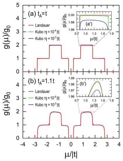
Figure A4.
Electrical conductance (g) at 0 K in units of obtained from the Landauer (red lines) and Kubo–Greenwood formulas using (blue lines) and (green lines) as functions of the chemical potential (μ) for graphene ribbons with , , , (a,a′) and (b,b’) , whose magnifications are shown in (a’) and (b’).
In Figure A4 the Kubo conductance spectra are obtained from Equation (A20) for two imaginary parts of energy (blue lines) and (green lines), where the retarded Green’s function was calculated through from the Dyson equation for a Hamiltonian of 36 atoms since and for a dilute A-type RS lattice with and containing only dislocation hopping integrals and , whose boundary conditions were obtained from periodic leads of 200,000 transversal lines. Observe in Figure A4a’,b’ the coincidence between electrical conductance spectra from Landauer and Kubo formalisms when in the latter one.
Appendix C. Real-Space Renormalization Method for Dilute Rudin–Shapiro Dual Channels
The Rudin–Shapiro (RS) sequence of generation k, , can be built using the substitution rules (12) or addition rules (13). The latter can be summarized into a single equation given by
whose subindices α, β and γ denote A, B, C or D-type RS sequence according to Table A2.

Table A2.
Addition rules for all type Rudin–Shapiro sequences.
Table A2.
Addition rules for all type Rudin–Shapiro sequences.
| α-Type | β-Type | γ-Type |
|---|---|---|
| A | A | B |
| B | A | C |
| C | D | B |
| D | D | C |
Let us consider an RS dual channel with bond disorder formed by alternating hopping integrals and , instead of letters A, B, C and D in the RS sequences, being with Moreover, a dilute RS dual channel can be built using periodic RS segments of generation formed by hopping integrals and placing a single hopping integral defect at the beginning of , while subsequent generations of dilute RS dual channels are constructed following the standard addition rule (A21) and Table A2. For example, dilute RS dual channels with are presented in Table A3.

Table A3.
Dilute Rudin–Shapiro dual channels with m = 2.
Table A3.
Dilute Rudin–Shapiro dual channels with m = 2.
| Generation | A-Type | B-Type | C-Type | D-Type |
|---|---|---|---|---|
| 1 | ||||
| 2 | ||||
| 3 |
Note: Symbol meaning  .
.
In this appendix, a new real-space renormalization method is developed for dilute RS dual channels, as an extension of that for single channels developed in reference [37], where the freedom degrees of interior sites are removed but their exact participation is maintained in the results. As an example, we present in Figure A5 this renormalization procedure for A-type RS dual channels by starting from generation one, which consists of six sites (blue spheres) with on-site energies and , respectively, for up and down sites, as well as hopping integrals (violet lines) and (red lines). The central sites located at the second transversal line can be renormalized by reducing the six-site dual channel into a four-site one with effective on-site energies , , and , respectively, for left-up, left-down, right-up and right-down sites, as well as effective hopping integrals and , correspondingly denoting up horizontal, down horizontal, left vertical, right vertical, decreasing diagonal and increasing diagonal bonds. Using the addition rule for A-type RS dual channels given by Equation (A21) and Table A2, this four sites dual channel is concatenated to another four-site renormalized B-type RS dual channel to build a six-site dual channel of generation 2, where the on-site energies of central sites are and respectively for up and down ones connected by the hopping integral , represented by a double line.
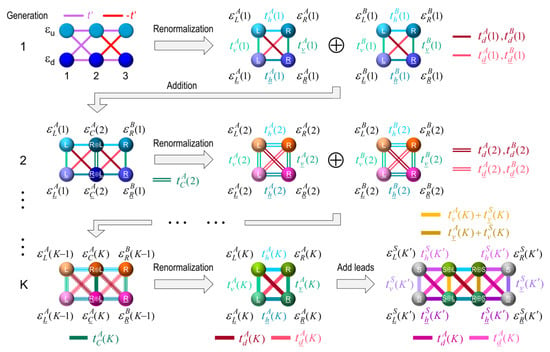
Figure A5.
Schematic representation of the renormalization procedure to build an A-type RS dual channel of generation K connected to two periodic leads of generation K’ (gray spheres), where the effective on-site energies and hopping integrals are respectively denoted as and for , and .
In general, for an α-type RS dual channel of generation k, similar addition and renormalization procedures were carried out. The effective on-site energies with and hopping integrals , being , of four-site dual channel can be obtained from the stationary Schrödinger equation:
where I is the identity matrix, H is the Hamiltonian of a concatenated six-site dual channel built from two dual channels of generations and is the electronic wavefunction with . Equation (A22) can be rewritten as
whose two central equations can be considered as a set of equations for and , with solutions given by
where
and
where
with
Substituting Equation (A24) into (A23), we obtain the stationary Schrödinger equation of a four-site dual channel given by
where
and
These effective on-site energies and hopping integrals are those indicated in Figure A5.
On the other hand, the electronic density of states (DOS) for an α-type RS dual channel of generation k evaluated at energy E can be written as [22]
where is the number of sites in the dual channel and is the j-th diagonal element of retarded Green’s function evaluated at . Extending the real-space renormalization method developed for Fibonacci chains [37,38], the of (A32) can be rewritten as
where are the renormalization coefficients and with are elements of the Green’s function matrix, with and respectively being the up (down) left and right sites of the renormalized four-site dual channel, as illustrated in Figure A5. From Equation (A32) and the addition rule (A21), we have
where subindex C denotes the central sites at the union of two renormalized dual channels. Equation (A34) can be rewritten using Equation (A33) as
The Dyson equation of a six-site α-type RS dual channel (see Figure A5 for ) given by can be rewritten as
where , and then Equation (A36) represents the 36 equations of six effective sites. The two central equations of (A36) can be visualized as a system of equations for and , whose solutions are
Substituting Equation (A37) into (A35) and comparing it to Equation (A33), we obtain the following iteration relations for renormalization coefficients given by
with
and
where . The initial conditions for this renormalization method are
and
where . The elements of Green’s function in Equation (A33) are numerically calculated from the Dyson equation, written as an matrix for the dual channel of the K-th generation connected to two periodic leads at its ends, as illustrated at the end of Figure A5.
References
- Novoselov, K.S.; Geim, A.K.; Morozov, S.V.; Jiang, D.; Zhang, Y.; Dubonos, S.V.; Grigorieva, I.V.; Firsov, A.A. Electric field effect in atomically thin carbon films. Science 2004, 306, 666–669. [Google Scholar] [CrossRef]
- Bolotin, K.I.; Sikes, K.J.; Jiang, Z.; Klima, M.; Fudenberg, G.; Hone, J.; Kim, P.; Stormer, H.L. Ultrahigh electron mobility in suspended graphene. Solid State Commun. 2008, 146, 351–355. [Google Scholar] [CrossRef]
- Balandin, A.A.; Ghosh, S.; Bao, W.; Calizo, I.; Teweldebrhan, D.; Miao, F.; Lau, C.N. Superior thermal conductivity of single-layer graphene. Nano Lett. 2008, 8, 902–907. [Google Scholar] [CrossRef]
- Lee, C.; Wei, X.; Kysar, J.W.; Hone, J. Measurement of the elastic properties and intrinsic strength of monolayer graphene. Science 2008, 321, 385–388. [Google Scholar] [CrossRef]
- Dhinakaran, V.; Lavanya, M.; Vigneswari, K.; Ravichandran, M.; Vijayakumar, M.D. Review on exploration of graphene in diverse applications and its future horizon. Mater. Today Proc. 2020, 27, 824–828. [Google Scholar] [CrossRef]
- Schedin, F.; Geim, A.K.; Morozov, S.V.; Hill, E.W.; Blake, P.; Katsnelson, M.I.; Novoselov, K.S. Detection of individual gas molecules adsorbed on graphene. Nat. Mater. 2007, 6, 652–655. [Google Scholar] [CrossRef] [PubMed]
- Béraud, A.; Sauvage, M.; Bazán, C.M.; Tie, M.; Bencherifa, A.; Bouilly, D. Graphene field-effect transistors as bioanalytical sensors: Design, operation and performance. Analyst 2021, 146, 403–428. [Google Scholar] [CrossRef] [PubMed]
- Wang, S.; Qi, X.; Hao, D.; Moro, R.; Ma, Y.; Ma, L. Recent advances in graphene-based field-effect-transistor biosensors: A review on biosensor designing strategy. J. Electrochem. Soc. 2022, 169, 027509. [Google Scholar] [CrossRef]
- Wang, M.; Yang, E.-H. THz applications of 2D materials: Graphene and beyond. Nano-Struct. Nano-Objects 2018, 15, 107–113. [Google Scholar] [CrossRef]
- Liu, J.; Li, X.; Jiang, R.; Yang, K.; Zhao, J.; Khan, S.A.; He, J.; Liu, P.; Zhu, J.; Zeng, B. Recent progress in the development of graphene detector for terahertz detection. Sensors 2021, 21, 4987. [Google Scholar] [CrossRef]
- Lone, S.; Bhardwaj, A.; Pandit, A.K.; Gupta, S.; Mahajan, S. A review of graphene nanoribbon field-effect transistor structures. J. Electron. Mater. 2021, 50, 3169–3186. [Google Scholar] [CrossRef]
- Freitag, M.; Steiner, M.; Martin, Y.; Perebeinos, V.; Chen, Z.; Tsang, J.C.; Avouris, P. Energy dissipation in graphene field-effect transistors. Nano Lett. 2009, 9, 1883–1888. [Google Scholar] [CrossRef]
- Yu, G.L.; Jalil, R.; Belle, B.; Mayorov, A.S.; Blake, P.; Schedin, F.; Morozov, S.V.; Ponomarenko, L.A.; Chiappini, F.; Wiedmann, S.; et al. Interaction phenomena in graphene seen through quantum capacitance. Proc. Natl. Acad. Sci. USA 2013, 110, 3282–3286. [Google Scholar] [CrossRef] [PubMed]
- Wen, R.; Jiang, Z.; Miao, R.; Wang, L.; Liang, Y.; Deng, J.; Shao, Q.; Zhang, J. Electronic transport properties of B/N/P co-doped armchair graphene nanoribbon field effect transistor. Diam. Relat. Mater. 2022, 124, 108893. [Google Scholar] [CrossRef]
- Radsar, T.; Khalesi, H.; Ghods, V.; Izadbakhsh, A. Effects of channel dimension and doping concentration of source and drain contacts on GNRFET performance. Silicon 2021, 13, 3337–3350. [Google Scholar] [CrossRef]
- Saltzgaber, G.; Wojcik, P.; Sharf, T.; Leyden, M.R.; Wardini, J.L.; Heist, C.A.; Adenuga, A.A.; Remcho, V.T.; Minot, E.D. Scalable graphene field-effect sensors for specific protein detection. Nanotechnology 2013, 24, 355502. [Google Scholar] [CrossRef]
- Sánchez, V.; Wang, C. Real space theory for electron and phonon transport in aperiodic lattices via renormalization. Symmetry 2020, 12, 430. [Google Scholar] [CrossRef]
- Shylau, A.A.; Kłos, J.W.; Zozoulenko, I.V. Capacitance of graphene nanoribbons. Phys. Rev. B 2009, 80, 205402. [Google Scholar] [CrossRef]
- Griffiths, D.J. Introduction to Electrodynamics, 4th ed.; Cambridge University Press: Cambridge, UK, 2017; pp. 106–190. [Google Scholar]
- Son, Y.-W.; Cohen, M.L.; Louie, S.G. Energy gaps in graphene nanoribbons. Phys. Rev. Lett. 2006, 97, 216803. [Google Scholar] [CrossRef]
- Fernández-Rossier, J.; Palacios, J.J.; Brey, L. Electronic structure of gated graphene and graphene ribbons. Phys. Rev. B 2007, 75, 205441. [Google Scholar] [CrossRef]
- Economou, E.N. Green’s Functions in Quantum Physics, 3rd ed.; Springer: Berlin/Heidelberg, Germany, 2006; pp. 14–16, 184. [Google Scholar]
- Datta, S. Lessons from Nanoelectronics. A New Perspective on Transport—Part A: Basic Concepts, 2nd ed.; World Scientific: Singapore, 2017; pp. 32, 123. [Google Scholar]
- Landauer, R. Electrical resistance of disordered one-dimensional lattices. Philos. Mag. 1970, 21, 863–867. [Google Scholar] [CrossRef]
- Cao, Q.; Geng, X.; Wang, H.; Wang, P.; Liu, A.; Lan, Y.; Peng, Q. A review of current development of graphene mechanics. Crystals 2018, 8, 357. [Google Scholar] [CrossRef]
- Yang, G.; Li, L.; Lee, W.B.; Ng, M.C. Structure of graphene and its disorders: A review. Sci. Technol. Adv. Mater. 2018, 19, 613–648. [Google Scholar] [CrossRef] [PubMed]
- Pires, M.A.; Duarte-Queirós, S.M. Quantum walks with sequential aperiodic jumps. Phys. Rev. E 2020, 102, 012104. [Google Scholar] [CrossRef]
- Maciá, E. Aperiodic Structures in Condensed Matter: Fundamentals and Applications; CRC Press: Boca Raton, FL, USA, 2009; p. 130. [Google Scholar]
- Zhong, H.; Zhang, Z.; Xu, H.; Qiu, C.; Peng, L.-M. Comparison of mobility extraction methods based on field-effect measurements for graphene. AIP Adv. 2015, 5, 057136. [Google Scholar] [CrossRef]
- Xia, F.; Perebeinos, V.; Lin, Y.; Wu, Y.; Avouris, P. The origins and limits of metal-graphene junction resistance. Nat. Nanotechnol. 2011, 6, 179–184, see also supplementary information. [Google Scholar] [CrossRef]
- Schroder, D.K. Semiconductor and Material and Device Characterization, 3rd ed.; John Wiley & Sons: Hoboken, NJ, USA, 2005; p. 146. [Google Scholar]
- Sutton, A.P. Electronic Structure of Materials; Clarendon Press: Oxford, UK, 1993; p. 58. [Google Scholar]
- Abhilash, T.S.; De Alba, R.; Zhelev, N.; Craighead, H.G.; Parpia, J.M. Transfer printing of CVD graphene FETs on patterned substrates. Nanoscale 2015, 7, 14109–14113. [Google Scholar] [CrossRef]
- Sánchez, V.; Sánchez, F.; Wang, C. Independent channel method for nanoribbons with dislocation and Fano defects. Phys. Status Solidi B 2021, 258, 2100095. [Google Scholar] [CrossRef]
- Nadri, F.; Mardaani, M.; Rabani, H. Semi-analytic study on the conductance of a lengthy armchair honeycomb nanoribbon including vacancies, defects, or impurities. Chin. Phys. B 2019, 28, 017202. [Google Scholar] [CrossRef]
- Sánchez, V.; Wang, C. Kubo conductivity in two-dimensional Fibonacci lattices. J. Non-Cryst. Solids 2003, 329, 151–154. [Google Scholar] [CrossRef]
- Sánchez, V.; Wang, C. Application of renormalization and convolution methods to the Kubo-Greenwood formula in multidimensional Fibonacci systems. Phys. Rev. B 2004, 70, 144207. [Google Scholar] [CrossRef]
- Sánchez, F.; Sánchez, V.; Wang, C. Renormalization approach to the electronic localization and transport in macroscopic generalized Fibonacci lattices. J. Non-Cryst. Solids 2016, 450, 194–208. [Google Scholar] [CrossRef]
Publisher’s Note: MDPI stays neutral with regard to jurisdictional claims in published maps and institutional affiliations. |
© 2022 by the authors. Licensee MDPI, Basel, Switzerland. This article is an open access article distributed under the terms and conditions of the Creative Commons Attribution (CC BY) license (https://creativecommons.org/licenses/by/4.0/).