
Highly Stable, Graphene-Wrapped, Petal-like, Gap-Enhanced Raman Tags

 and
and 
Abstract
:1. Introduction
2. Materials and Methods
2.1. Materials
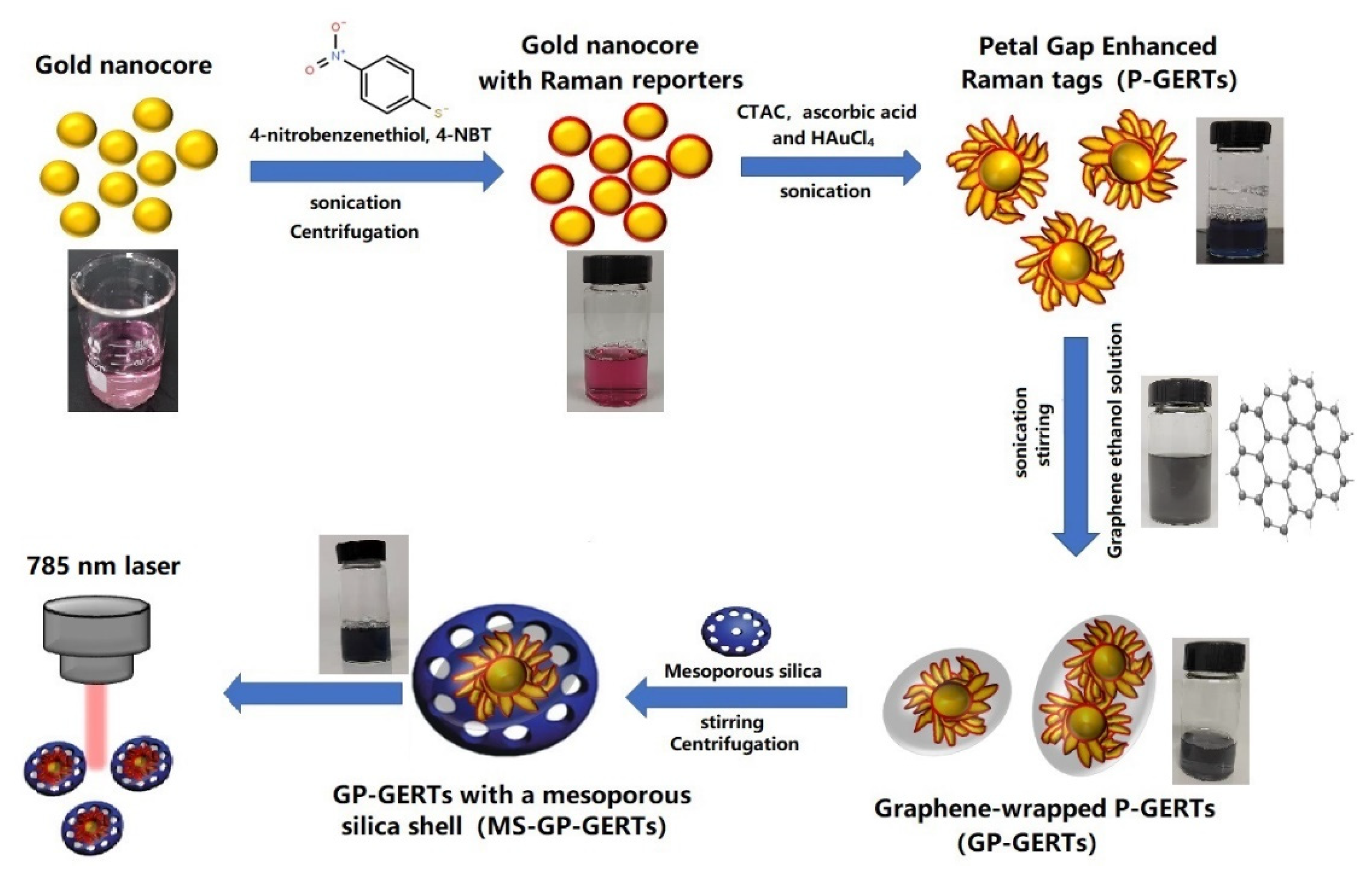
2.2. Synthesis of GP-GERTs and MS-GP-GERTs
2.3. Characterization of GERTs
2.4. Stability Experiments of MS-GP-GERTs
3. Results
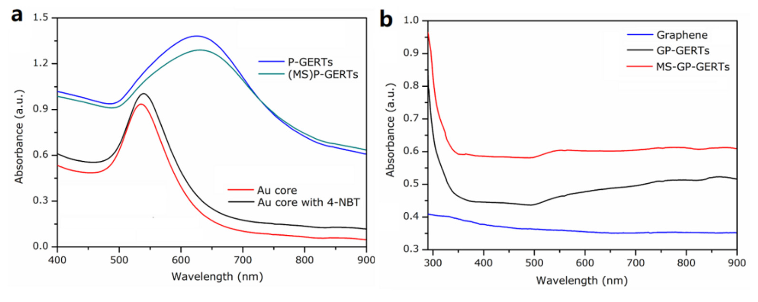
3.1. UV-Vis Absorption Spectroscopy
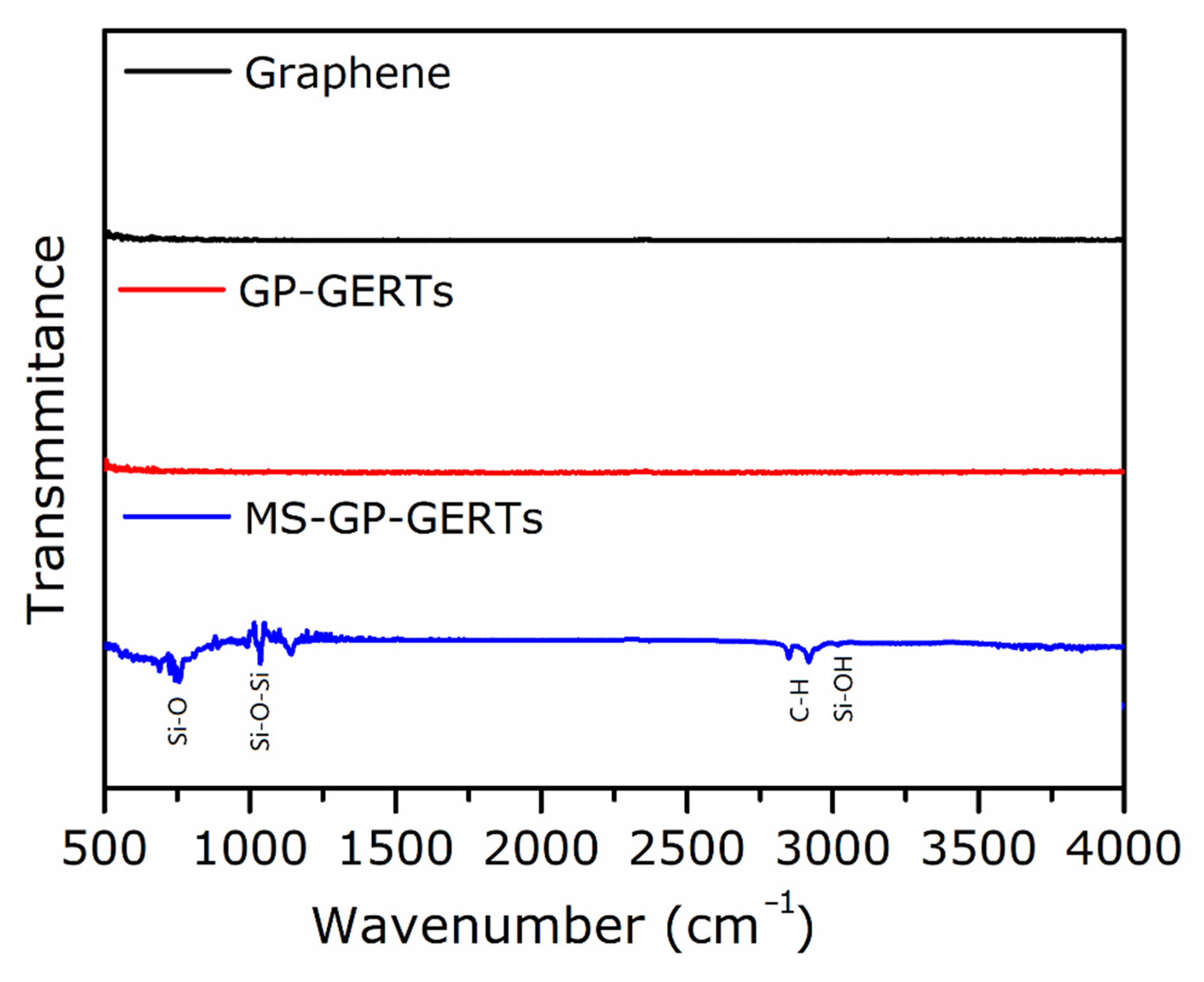
3.2. Fourier Transform Infrared Spectroscopy (FTIR)
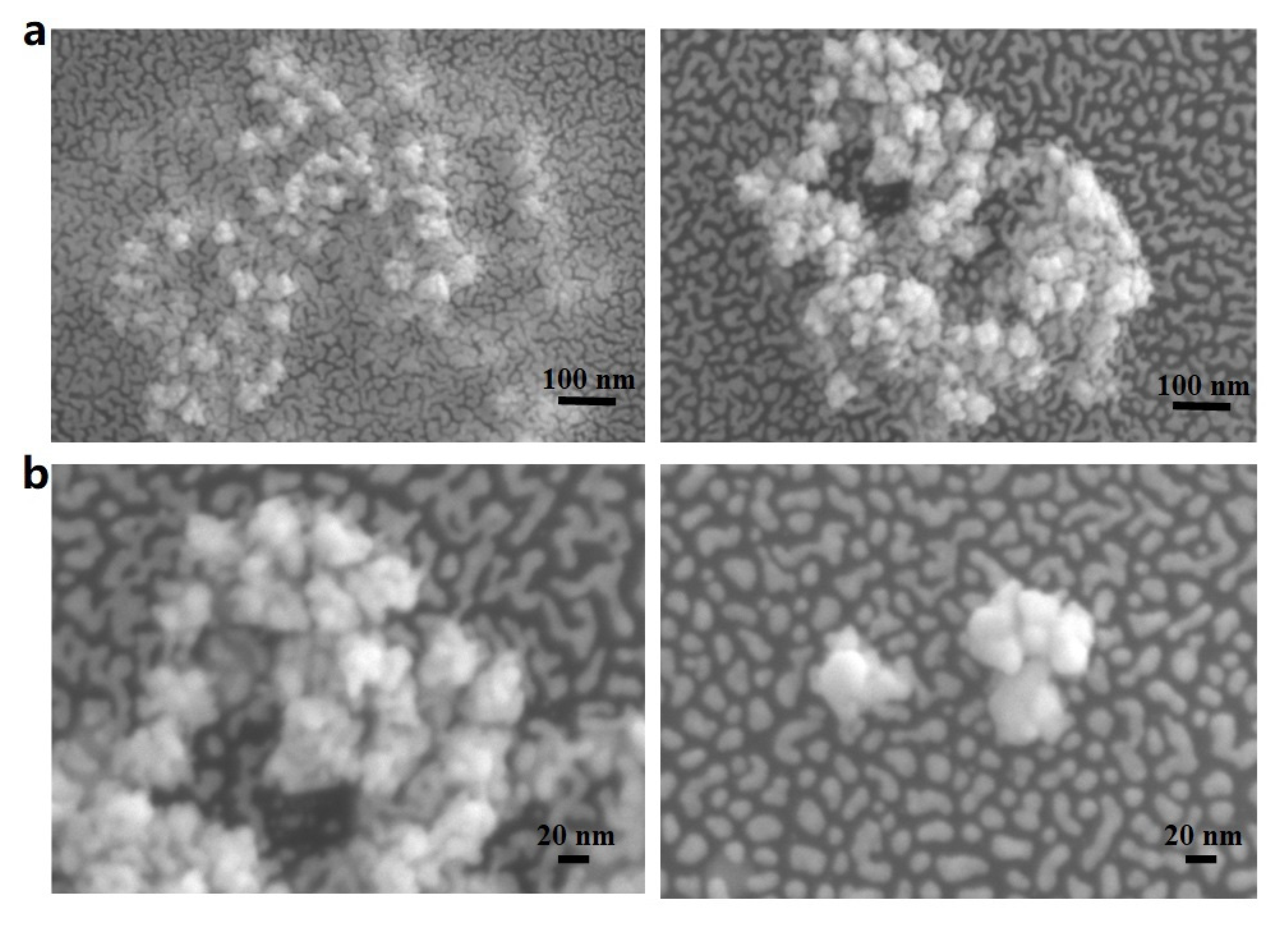
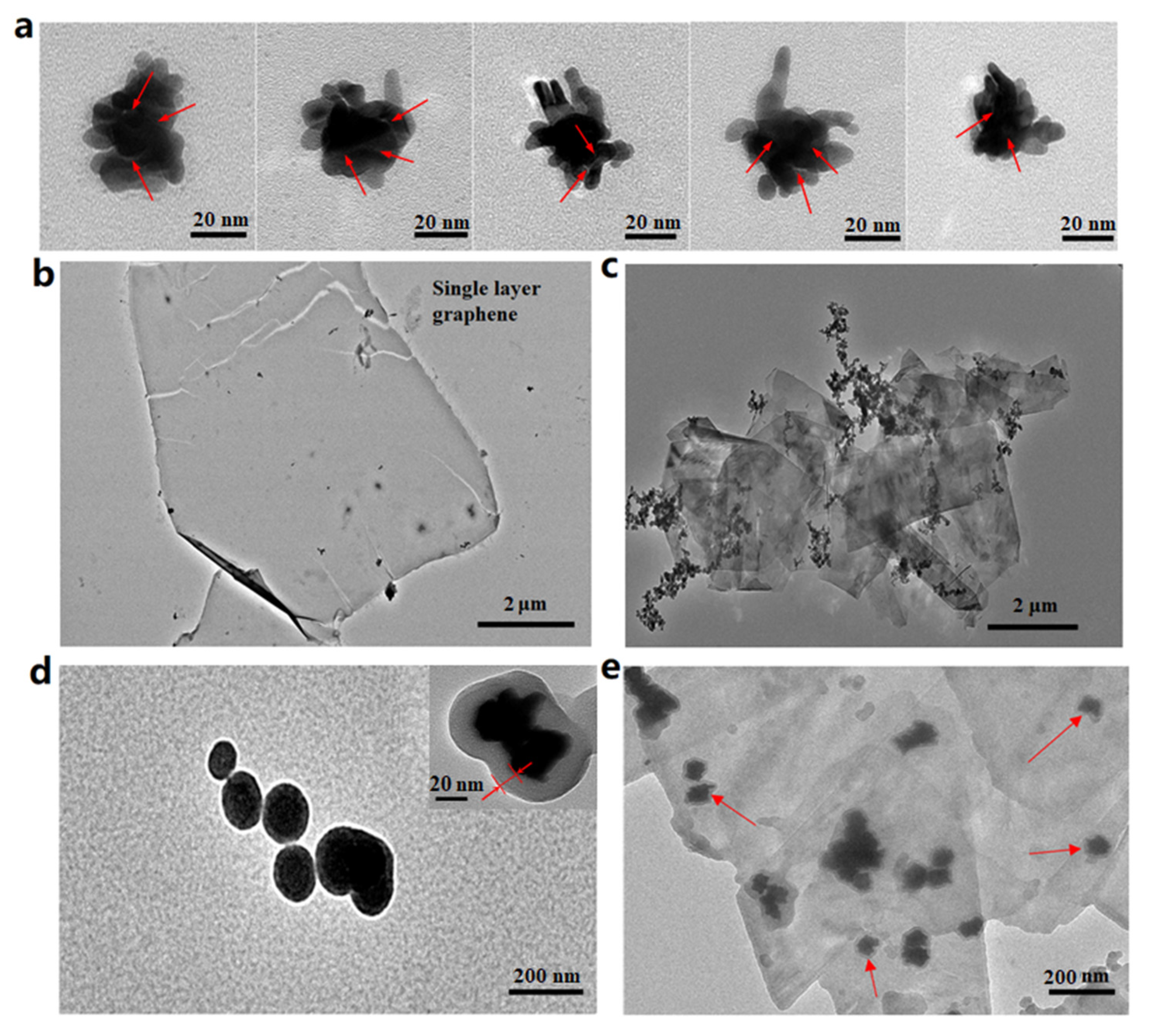
3.3. SEM and TEM
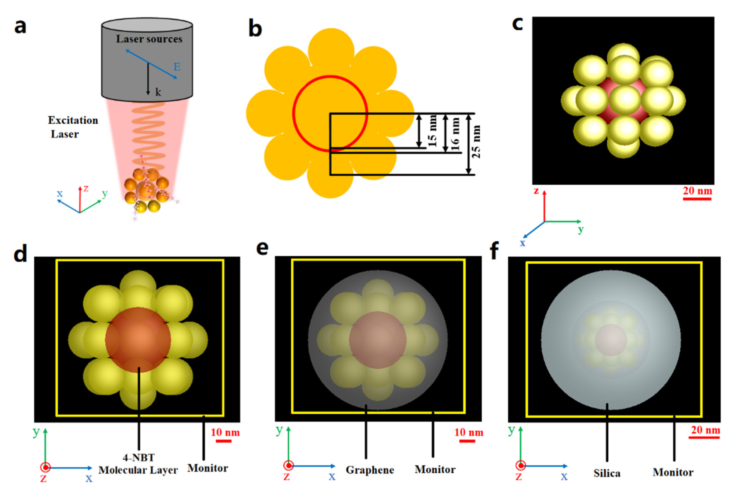
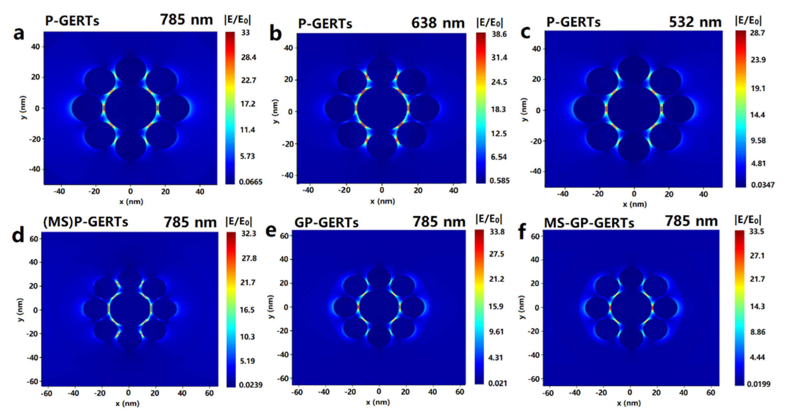
3.4. Simulation
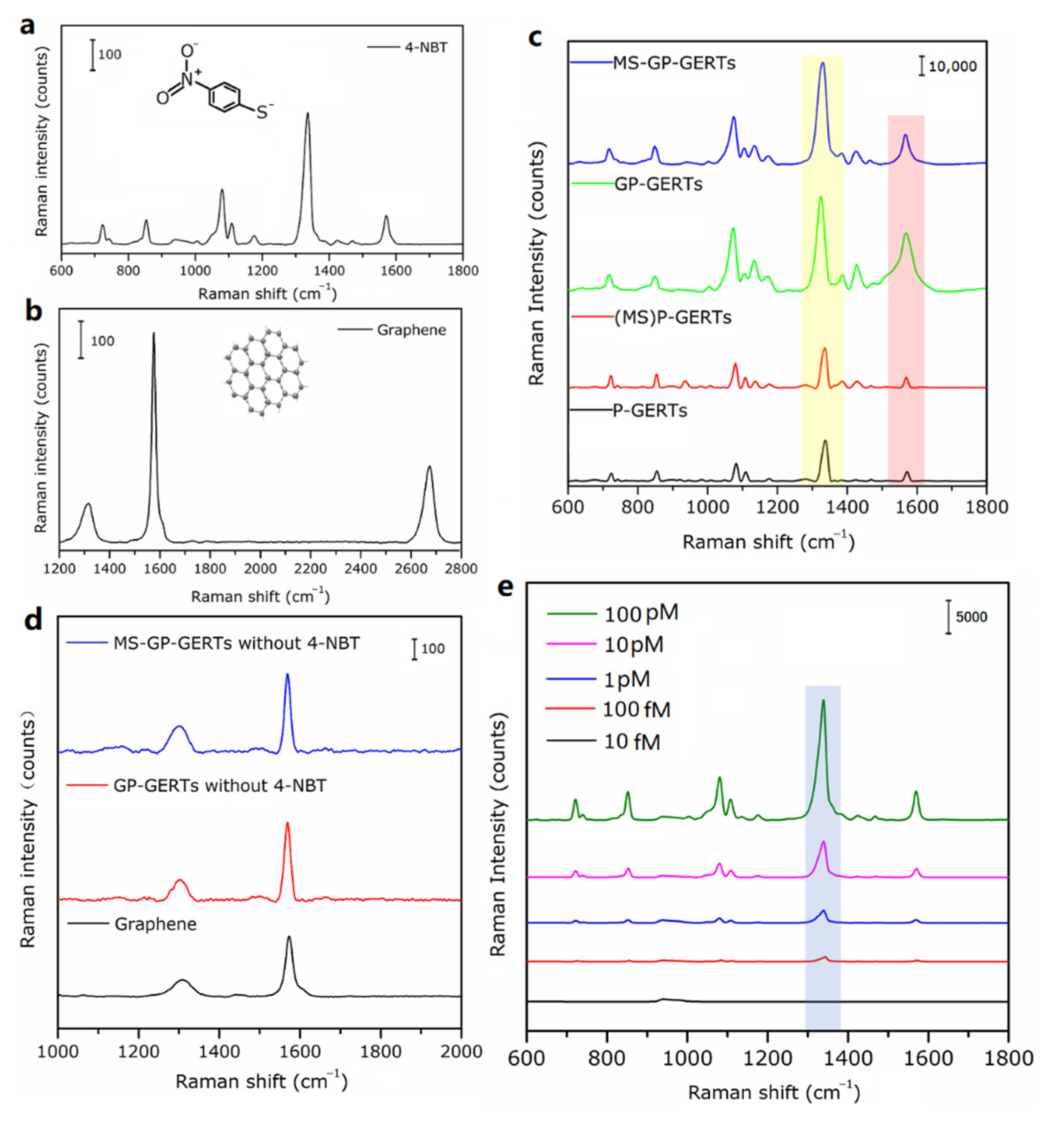
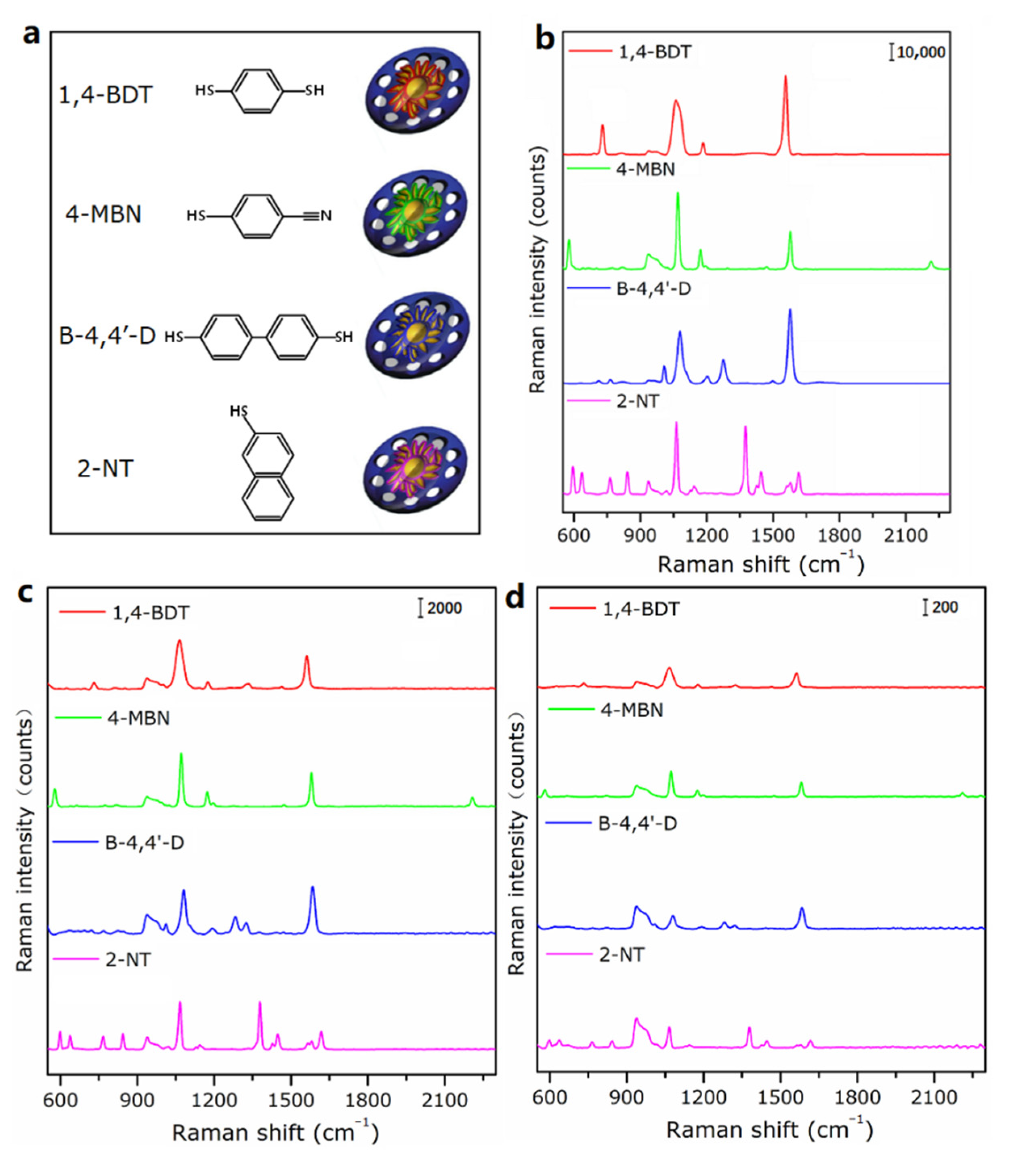
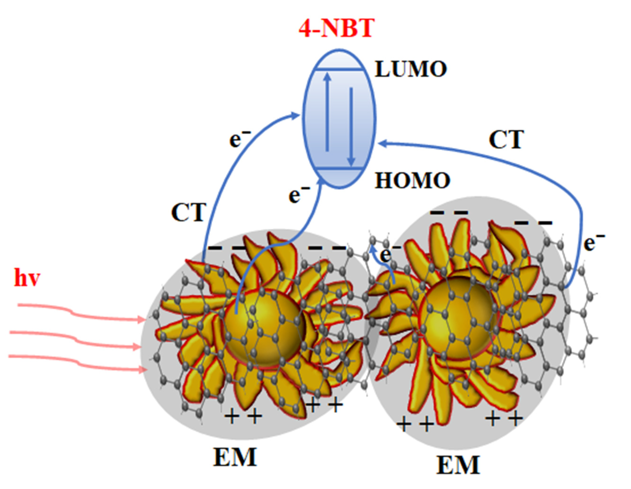
3.5. Raman Spectra and Enhancement Mechanism of GERTs
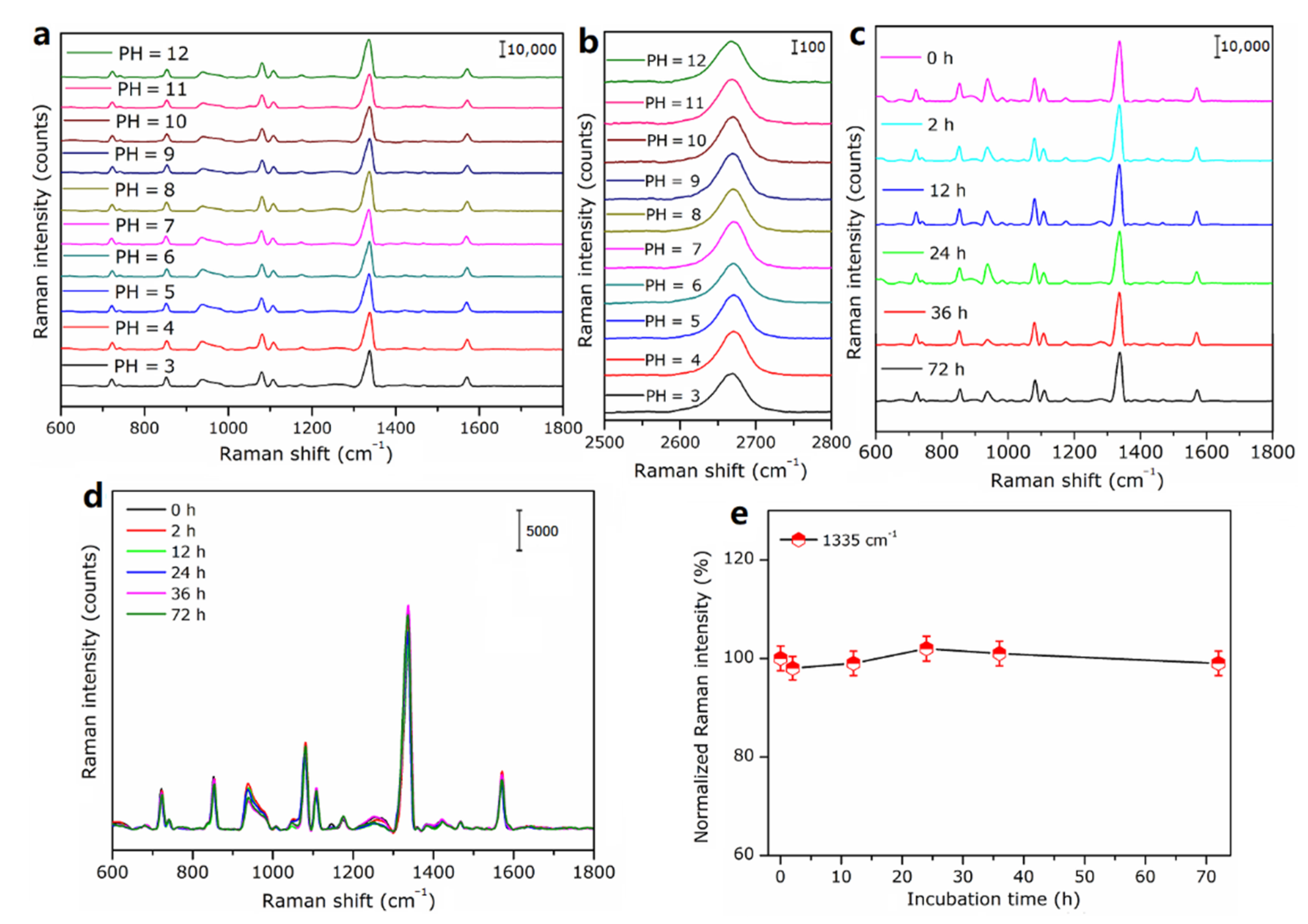
3.6. Stability of MS-GP-GERTs
4. Conclusions
Author Contributions
Funding
Institutional Review Board Statement
Informed Consent Statement
Data Availability Statement
Acknowledgments
Conflicts of Interest
References
- Ding, S.Y.; You, E.M.; Tian, Z.Q.; Martin, M. Electromagnetic theories of surface-enhanced Raman spectroscopy. Chem. Soc. Rev. 2017, 46, 4042–4076. [Google Scholar] [CrossRef] [PubMed]
- Muehlethaler, C.; Leona, M.; Lombardi, J.R. Review of surface enhanced Raman scattering applications in forensic science. Anal. Chem. 2016, 88, 152–169. [Google Scholar] [CrossRef] [PubMed]
- Langer, J.; Jimenez, A.; Berasturi, D.; Aizpurua, J.; Alvarez-Puebla, R.A.; Auguie, B.; Baumberg, J.J.; Bazan, G.C.; Bell, S.E.J.; Boisen, A.; et al. Present and future of surface-enhanced Raman scattering. ACS. Nano 2019, 14, 28–117. [Google Scholar] [CrossRef] [PubMed] [Green Version]
- Li, J.F.; Huang, Y.F.; Ding, Y.; Yang, Z.L.; Li, S.B.; Zhou, X.S.; Fan, F.R.; Zhang, W.; Zhou, Z.Y.; Wu, D.Y.; et al. Shell-isolated nanoparticle-enhanced Raman spectroscopy. Nature 2010, 464, 392–395. [Google Scholar] [CrossRef] [PubMed]
- Kneipp, J.; Kneipp, H.; Kneipp, K. SERS—A single-molecule and nanoscale tool for bioanalytics. Chem. Soc. Rev. 2008, 37, 1052–1060. [Google Scholar] [CrossRef] [PubMed]
- Wang, Y.; Yan, B.; Chen, L. SERS tags: Novel optical nanoprobes for bioanalysis. Chem. Rev. 2013, 113, 1391–1428. [Google Scholar] [CrossRef]
- Wang, Z.; Zong, S.; Wu, L.; Zhu, D.; Cui, Y.P. SERS-activated platforms for immunoassay: Probes, encoding methods, and applications. Chem. Rev. 2017, 117, 7910–7963. [Google Scholar] [CrossRef]
- Gandra, N.; Singamaneni, S. Bilayered raman-intense gold nanostructures with hidden tags (brights) for high-resolution bioimaging. Adv. Mater. 2013, 25, 1022–1027. [Google Scholar] [CrossRef]
- Kang, J.W.; So, P.T.C.; Dasari, R.R.; Lim, D.K. High resolution live cell Raman imaging using subcellular organelle-targeting SERS-sensitive gold nanoparticles with highly narrow intra-nanogap. Nano Lett. 2015, 15, 1766–1772. [Google Scholar] [CrossRef] [Green Version]
- Bao, Z.; Zhang, Y.; Tan, Z.; Yin, X.; Di, W.; Ye, J. Gap-enhanced Raman tags for high-contrast sentinel lymph node imaging. Biomaterials 2018, 163, 105–115. [Google Scholar] [CrossRef]
- Khlebtsov, B.N.; Bratashov, D.N.; Byzova, N.A.; Dzantiev, B.B.; Khlebtsov, N.G. SERS-based lateral flow immunoassay of troponin I by using gap-enhanced Raman tags. Nano Res. 2019, 12, 413–420. [Google Scholar] [CrossRef]
- Gu, Y.; He, C.; Zhang, Y.; Lin, L.; Thackray, B.D.; Ye, J. Gap-enhanced Raman tags for physically unclonable anticounterfeiting labels. Nat. Commun. 2020, 11, 516. [Google Scholar] [CrossRef] [PubMed]
- Khlebtsov, B.; Pylaev, T.; Khanadeev, V.; Bratashov, D.; Khlebtsov, N. Quantitative and multiplex dot-immunoassay using gap-enhanced Raman tags. RSC Adv. 2017, 7, 40834–40841. [Google Scholar] [CrossRef] [Green Version]
- Zhang, Y.; Gu, Y.; He, J.; Thackray, B.D.; Ye, J. Ultrabright gap-enhanced Raman tags for high-speed bioimaging. Nat. Commun. 2019, 10, 3905. [Google Scholar] [CrossRef] [PubMed] [Green Version]
- Geim, A.K. Graphene: Status and prospects. Science. 2009, 324, 1530–1534. [Google Scholar] [CrossRef] [Green Version]
- Tiwari, S.K.; Sahoo, S.; Wang, N.; Huczko, A. Graphene research and their outputs: Status and prospect. J. Sci.-Adv. Mater. Devices 2020, 5, 10–29. [Google Scholar] [CrossRef]
- Ren, W.; Cheng, H.M. The global growth of graphene. Nat. Nanotechnol. 2014, 9, 726–730. [Google Scholar] [CrossRef]
- Zhang, X.; Jing, Q.; Ao, S.; Schneider, G.F.; Kireev, D.; Zhang, Z.J.; Fu, W.Y. Ultrasensitive field-effect biosensors enabled by the unique electronic properties of graphene. Small 2020, 16, 1902820. [Google Scholar] [CrossRef]
- Guo, S.; Zhang, Y.; Ge, Y.; Zhang, S.L.; Zeng, H.B.; Zhang, H. 2D V-V binary materials: Status and challenges. Adv. Mater. 2019, 31, 1902352. [Google Scholar] [CrossRef]
- Zheng, T.T.; Zhou, Y.; Feng, E.D.; Tian, Y. Surface-enhanced Raman scattering on 2D nanomaterials: Recent developments and applications. Chin. J. Chem. 2021, 39, 745–756. [Google Scholar] [CrossRef]
- Huh, S.; Park, J.; Kim, Y.S.; Kim, K.S.; Hong, B.H.; Nam, J.M. UV/ozone-oxidized large-scale graphene platform with large chemical enhancement in surface-enhanced Raman scattering. ACS Nano 2011, 5, 9799–9806. [Google Scholar] [CrossRef] [PubMed]
- Jiang, T.; Wang, X.L.; Tang, S.S.; Zhou, J.; Gu, C.J.; Tang, J. Seed-mediated synthesis and SERS performance of graphene oxide-wrapped Ag nanomushroom. Sci. Rep. 2017, 7, 1–9. [Google Scholar] [CrossRef] [PubMed]
- Yang, W.; Li, Z.; Lu, Z.; Yu, J.; Huo, Y.Y.; Man, B.Y.; Pan, J.; Si, H.P.; Jiang, S.Z.; Zhang, C. Graphene-Ag nanoparticles-cicada wings hybrid system for obvious SERS performance and DNA molecular detection. Opt. Express 2019, 27, 3000–3013. [Google Scholar] [CrossRef] [PubMed]
- Wang, J.C.; Qiu, C.C.; Pang, H.; Wu, J.Y.; Sun, M.T.; Liu, D.M. High-performance SERS substrate based on perovskite quantum dot–graphene/nano-Au composites for ultrasensitive detection of rhodamine 6G and p-nitrophenol. J. Mater. Chem. C 2021, 9, 9011–9020. [Google Scholar] [CrossRef]
- Qiu, X.J.; You, X.R.; Chen, X.; Chen, H.L.; Dhinakar, A.; Liu, S.H.; Guo, Z.Y.; Wu, J.; Liu, Z.M. Development of graphene oxide-wrapped gold nanorods as robust nanoplatform for ultrafast near-infrared SERS bioimaging. Int. J. Nanomed. 2017, 12, 43–49. [Google Scholar] [CrossRef] [Green Version]
- Gong, T.C.; Zhang, J.; Zhu, Y.; Wang, X.Y.; Zhang, X.L.; Zhang, J. Optical properties and surface-enhanced Raman scattering of hybrid structures with Ag nanoparticles and graphene. Carbon 2016, 102, 245–254. [Google Scholar] [CrossRef]
- Quan, J.M.; Zhang, J.; Li, J.Y.; Zhang, X.L.; Wang, M.; Wang, N.; Zhu, Y. Three-dimensional AgNPs-graphene-AgNPs sandwiched hybrid nanostructures with sub-nanometer gaps for ultrasensitive surface-enhanced Raman spectroscopy. Carbon 2019, 147, 105–111. [Google Scholar] [CrossRef]
- Zhang, Y.J.; Chen, Q.Q.; Chen, X.; Wang, A.; Tian, Z.Q.; Li, J.F. Graphene-coated Au nanoparticle-enhanced Raman spectroscopy. J. Raman Spectrosc. 2021, 52, 439–445. [Google Scholar] [CrossRef]
- Haiss, W.; Thanh, N.T.K.; Aveyard, J.; Fernig, D.G. Determination of size and concentration of gold nanoparticles from UV−Vis spectra. Anal. Chem. 2007, 79, 4215–4221. [Google Scholar] [CrossRef]
- Zhang, Y.Q.; Qiu, Y.Y.; Lin, L.; Gu, H.C.; Xiao, Z.Y.; Ye, J. Ultraphotostable mesoporous silica-coated gap-enhanced Raman tags (GERTs) for high-speed bioimaging. ACS Appl. Mater. Interfaces 2017, 9, 3995–4005. [Google Scholar] [CrossRef]
- Bepete, G.; Anglaret, E.; Ortolani, L.; Morandi, V.; Huang, K.; Penicaud, A.; Drummond, C. Surfactant-free single-layer graphene in water. Nat. Chem. 2017, 9, 347–352. [Google Scholar] [CrossRef] [PubMed] [Green Version]
- Baumgartner, B.; Hayden, J.; Loizillon, J.; Steinbacher, S.; Grosso, D.; Lendl, B. Pore size-dependent structure of confined water in mesoporous silica films from water adsorption/desorption using ATR–FTIR spectroscopy. Langmuir 2019, 35, 11986–11994. [Google Scholar] [CrossRef] [PubMed]
- Shadmani, S.; Gabriel, L.; Hornyak, D.C.; Htet, K.; Tanujjal, B. Morphology and Visible Photoluminescence Modulation in Dye-free Mesoporous Silica Nanoparticles using a Simple Calcination Step. Mater. Res. Bull. 2022, 152, 111842. [Google Scholar] [CrossRef]
- Zhuang, X.; Miranda, P.B.; Kim, D.; Shen, Y.R. Mapping molecular orientation and conformation at interfaces by surface nonlinear optics. Phys. Rev. B 1999, 59, 12632–12640. [Google Scholar] [CrossRef] [Green Version]
- Cecchet, F.; Lis, D.; Guthmuller, J.; Champagne, B.; Caudano, Y.; Silien, C.; Mani, A.A.; Thiry, P.A.; Peremans, A. Orientational Analysis of Dodecanethiol and p-Nitrothiophenol SAMs on Metals with Polarisation-Dependent SFG Spectroscopy. Chemphyschem 2010, 11, 607–615. [Google Scholar] [CrossRef]
- Cheon, S.; Kihm, K.D.; Kim, H.G.; Lim, G.; Park, J.S.; Lee, J.S. How to reliably determine the complex refractive index (RI) of graphene by using two independent measurement constraints. Sci. Rep. 2014, 4, 6364. [Google Scholar] [CrossRef]
- Lin, D.H.; Qin, T.Q.; Wang, Y.Q.; Sun, X.Y.; Chen, L.X. Graphene oxide wrapped SERS tags: Multifunctional platforms toward optical labeling, photothermal ablation of bacteria, and the monitoring of killing effect. ACS Appl. Mater. Interfaces 2014, 6, 1320–1329. [Google Scholar] [CrossRef]
- Zhang, X.L.; Wang, N.; Liu, R.J.; Wang, X.Y.; Zhu, Y.; Zhang, J. SERS and the photo-catalytic performance of Ag/TiO2/graphene composites. Opt. Mater. Express 2018, 8, 704. [Google Scholar] [CrossRef]
- Xu, W.; Mao, N.; Zhang, J. Graphene: A platform for surface-enhanced Raman spectroscopy. Small 2013, 9, 1206–1224. [Google Scholar] [CrossRef]
- Kaushik, V.; Kagdada, H.L.; Singh, D.K.; Pathak, S. Enhancement of SERS effect in Graphene-Silver hybrids. Appl. Surf. Sci. 2022, 574, 151724. [Google Scholar] [CrossRef]
- Wang, Y.; Du, X.C.; Hu, A.J.; Hu, Y.; Gong, C.H.; Wang, X.F.; Xiong, J. Coupling enhancement mechanisms, materials, and strategies for surface-enhanced Raman scattering devices. Analyst 2021, 146, 5008–5032. [Google Scholar] [CrossRef] [PubMed]
- Trivedi, D.J.; Barrow, B.; Schatz, G.C. Understanding the chemical contribution to the enhancement mechanism in SERS: Connection with Hammett parameters. J. Chem. Phys. 2020, 153, 124706. [Google Scholar] [CrossRef] [PubMed]
- Valley, N.; Jensen, L.; Autschbach, J.; Schatz, G.C. Theoretical studies of surface enhanced hyper-Raman spectroscopy: The chemical enhancement mechanism. J. Chem. Phys. 2010, 133, 054103. [Google Scholar] [CrossRef] [PubMed]
- Zhu, B.; Wang, F.; Wang, G.; Gu, Y.Z. Oxygen-containing-defect-induced synergistic nonlinear optical enhancement of graphene/CdS nanohybrids under single pulse laser irradiation. Photonics Res. 2018, 6, 1158–1169. [Google Scholar] [CrossRef]
- Jiang, M.; Wang, Z.; Zhang, J. TiO2/AgNPs SERS substrate for the detection of multi-molecules with a self-cleaning and high enhancement factor using the UV-induced method. Opt. Mater. Express 2022, 12, 1010–1018. [Google Scholar] [CrossRef]
- Le Ru, E.C.; Blackie, E.; Meyer, M.; Etchegoin, P.G. Surface enhanced Raman scattering enhancement factors: A comprehensive study. J. Phys. Chem. C 2007, 111, 13794–13803. [Google Scholar] [CrossRef]
- Sergiienko, S.; Moor, K.; Gudun, K.; Yelemessova, Z.; Bukasov, R. Nanoparticle–nanoparticle vs. nanoparticle–substrate hot spot contributions to the SERS signal: Studying Raman labelled monomers, dimers and trimers. Phys. Chem. Chem. Phys. 2017, 19, 4478–4487. [Google Scholar] [CrossRef]
- Pugmire, D.L.; Tarlov, M.J.; Van Zee, R.D.; Naciri, J. Structure of 1, 4-benzenedimethanethiol self-assembled monolayers on gold grown by solution and vapor techniques. Langmuir 2003, 19, 3720–3726. [Google Scholar] [CrossRef]
- Camerlingo, C.; Verde, A.; Manti, L.; Meschini, R.; Delfino, I.; Lepore, M. Graphene-based Raman spectroscopy for pH sensing of X-rays exposed and unexposed culture media and cells. Sensors 2018, 18, 2242. [Google Scholar] [CrossRef] [Green Version]
- Zou, J.; Chen, Y.; Shu, X.; Li, X.; Song, Y.; Zhao, Z. Proper pH value enhances giant magneto-impedance effect of FINEMET/rGO composite ribbons by electroless plating. Mater. Sci. Eng. B 2021, 265, 115004. [Google Scholar] [CrossRef]
- Chen, H.Y.; Guo, D.; Gan, Z.F.; Jiang, L.; Chang, S.; Li, D.W. A phenylboronate-based SERS nanoprobe for detection and imaging of intracellular peroxynitrite. Microchim. Acta 2019, 186, 1–8. [Google Scholar] [CrossRef]
- Li, M.; Wu, J.; Ma, M.; Feng, Z.; Mi, Z.; Rong, P.; Liu, D. Alkyne-and nitrile-anchored gold nanoparticles for multiplex SERS imaging of biomarkers in cancer cells and tissues. Nanotheranostics 2019, 3, 113–119. [Google Scholar] [CrossRef]
- Zhang, Y.; Qian, J.; Wang, D.; Wang, Y.L.; He, S.L. Multifunctional gold nanorods with ultrahigh stability and tunability for in vivo fluorescence imaging, SERS detection, and photodynamic therapy. Angew. Chem. Int. Edit. 2013, 52, 1148–1151. [Google Scholar] [CrossRef]


Publisher’s Note: MDPI stays neutral with regard to jurisdictional claims in published maps and institutional affiliations. |
© 2022 by the authors. Licensee MDPI, Basel, Switzerland. This article is an open access article distributed under the terms and conditions of the Creative Commons Attribution (CC BY) license (https://creativecommons.org/licenses/by/4.0/).
Share and Cite
Chen, M.; Wang, B.; Wang, J.; Liu, H.; Chen, Z.; Xu, X.; Zhao, X. Highly Stable, Graphene-Wrapped, Petal-like, Gap-Enhanced Raman Tags. Nanomaterials 2022, 12, 1626. https://doi.org/10.3390/nano12101626
Chen M, Wang B, Wang J, Liu H, Chen Z, Xu X, Zhao X. Highly Stable, Graphene-Wrapped, Petal-like, Gap-Enhanced Raman Tags. Nanomaterials. 2022; 12(10):1626. https://doi.org/10.3390/nano12101626
Chicago/Turabian StyleChen, Ming, Bin Wang, Jingfan Wang, Hongliang Liu, Zhixiang Chen, Xiaoxuan Xu, and Xing Zhao. 2022. "Highly Stable, Graphene-Wrapped, Petal-like, Gap-Enhanced Raman Tags" Nanomaterials 12, no. 10: 1626. https://doi.org/10.3390/nano12101626
APA StyleChen, M., Wang, B., Wang, J., Liu, H., Chen, Z., Xu, X., & Zhao, X. (2022). Highly Stable, Graphene-Wrapped, Petal-like, Gap-Enhanced Raman Tags. Nanomaterials, 12(10), 1626. https://doi.org/10.3390/nano12101626