Article

Inclusion of 2D Transition Metal Dichalcogenides in Perovskite Inks and Their Influence on Solar Cell Performance

1
Dipartimento di Matematica e Fisica “E. De Giorgi”, Campus Ecotekne, Università del Salento, Via Arnesano, 73100 Lecce, Italy
2
CNR NANOTEC, c/o Campus Ecotekne, Institute of Nanotechnology, Via Monteroni, 73100 Lecce, Italy
3
School of Chemistry, Trinity College Dublin, Dublin 2, Ireland
4
CRANN and Amber, Trinity College Dublin, Dublin 2, Ireland
5
CENIMAT|i3N, Departamento de Ciência de Materiais, Faculdade de Ciências e Tecnologia Universidade NOVA de Lisboa and CEMOP/UNINOVA, Campus da Caparica, 2829-516 Caparica, Portugal
6
CNR NANOTEC, c/o Department of Chemistry, Institute of Nanotechnology, University of Bari ‘Aldo Moro’, Via Orabona 4, 70126 Bari, Italy
7
Department of Chemistry, University of Bari “Aldo Moro”, Via Orabona 4, 70126 Bari, Italy
*
Author to whom correspondence should be addressed.
Nanomaterials 2021, 11(7), 1706; https://doi.org/10.3390/nano11071706
Submission received: 13 May 2021 / Revised: 23 June 2021 / Accepted: 25 June 2021 / Published: 29 June 2021
(This article belongs to the Special Issue Mesoporous Materials and Nanoscale Phenomena in Hybrid Photovoltaics)

Abstract

:
Organic–inorganic hybrid perovskite materials have raised great interest in recent years due to their excellent optoelectronic properties, which promise stunning improvements in photovoltaic technologies. Moreover, two-dimensional layered materials such as graphene, its derivatives, and transition metal dichalcogenides have been extensively investigated for a wide range of electronic and optoelectronic applications and have recently shown a synergistic effect in combination with hybrid perovskite materials. Here, we report on the inclusion of liquid-phase exfoliated molybdenum disulfide nanosheets into different perovskite precursor solutions, exploring their influence on final device performance. We compared the effect of such additives upon the growth of diverse perovskites, namely CH3NH3PbI3 (MAPbI3) and triple-cation with mixed halides Csx (MA0.17FA0.83)(1−x)Pb (I0.83Br0.17)3 perovskite. We show how for the referential MAPbI3 materials the addition of the MoS2 additive leads to the formation of larger, highly crystalline grains, which result in a remarkable 15% relative improvement in power conversion efficiency. On the other hand, for the mixed cation–halide perovskite no improvements were observed, confirming that the nucleation process for the two materials is differently influenced by the presence of MoS2.

1. Introduction

Extensive, ongoing research has been performed to date towards the development of highly efficient and stable perovskite solar cells (PSC) [1]. Organic–inorganic metal halide perovskites, with the general formula ABX3 (where A is a cation, B is a divalent metal cation and X is a halide), are a class of semiconductors that have the potential to deliver high-efficiency photovoltaic devices at mild temperature processing conditions and low cost [2]. These materials feature unique optical and electronic properties, such as high carrier mobility, long charge diffusion length, low trap-state densities and intense broadband absorption [3].
Perovskite crystalline structure, morphology, dimension, and distribution of the poly crystallite perovskite thin films are critical factors that affect the optoelectronic and photovoltaic properties [4]. Currently, one of the main challenges for PSC development is the deposition of high-quality films with optimized morphology, large grains and which are pinhole-free. Many different approaches have been investigated to improve the film quality: annealing conditions [5], compositional [6] and solvent engineering [7], interfacial modification [8], deposition methods [9], and, finally, additive engineering [10,11,12,13]. The inclusion of additives into the perovskite precursor solution is widely adopted, as their presence impacts the final morphology of perovskite films [14], stabilizes the active crystalline phase [15], tunes the energy level alignment between material constituents, and suppresses non-radiative recombination in perovskite materials [16]. Furthermore, additives play an important role in perovskite crystal growth and can lead to a stronger control over nucleation and crystallization kinetics [11], or activate surface passivation mechanisms, achieving highly crystalline perovskite films that are suitable for device integration. Several types of additives have been added into perovskite precursor solutions, including polymers [13], molecules [17], organic [18,19] and inorganic [20] halide salts, inorganic acids [21], carbon-based materials and nanoparticles [22]. Within this collection, interesting perspectives involve the use of systems characterized by extended surfaces, such as two-dimensional (2D) materials, which could extend the interaction over a region of large perovskite grains [23,24,25].
Two-dimensional transition metal dichalcogenides (2D-TMD), obtained by liquid-phase exfoliation, are characterized by high electrical conductivity and charge carrier mobility, tunable optoelectronic properties, and offer the possibility of engineering their surfaces by physical or chemical methods. Therefore, with PSC advancement in mind, 2D-TMDs offer the possibility of integration into multiple features: as electrodes, as charge transporting layers, and/or as an additive to be used in the precursor solutions of perovskite active layers [26].
Two-dimensional flakes of MoS2, MoSe2 and TiS2 have recently been used as an interlayer between perovskite and either the hole transporting layer (HTL) or electron transporting layer (ETL) [27,28,29]. This prevents the formation of shunt contacts between the perovskite and the electrode and provides a more suitable energy band alignment between the perovskite active layer and the transporting layer. Finally, chemically exfoliated MoS2 was employed both as an additional component of the perovskite precursor solution and an interfacial layer to enhance PSC [30] efficiency in the p-i-n architecture with PEDOT:PSS as the HTL [30]. The inclusion of MoS2 enlarged the grain size and improved the crystalline quality of MAPbI3 perovskite films. Furthermore, due to the incorporation of an MoS2 interlayer, the direct contact between hydrophilic PEDOT:PSS and MAPbI3 film is avoided, preventing early deterioration of device performance.
In this work, we focused on the inclusion of MoS2 TMD sheets into a perovskite precursor solution of two representative benchmark materials, MAPbI3 and mixed cation-halide CsMAFAPbIBr (MA = methylammonium, FA = formamidinium), with the aim of improving our knowledge of the role of such an additive in diverse perovskite formulations. The solar cell architecture was an inverted p-i-n structure employing organic transporting layers as sketched in Figure 1a,b. Our findings show that the integration of MoS2 into the MAPbI3 perovskite active layer leads to larger grain size, resulting in improved device performance. In fact, the PSCs show a 15% improvement in power conversion efficiency (PCE) through embedding TMDs in the perovskite active layer. Conversely, identical additive engineering for CsMAFAPbIBr perovskite did not show similar device improvements, suggesting that the polycrystalline perovskite film formation is influenced differently by the presence of 2D MoS2 depending on the different ions involved in solution.

2. Experimental Section

2.1. Materials

Lead (II) iodide ultradry (PbI2, metals basis, 99.999%) was purchased from Alfa Aesar (Kandel, Germany), methylammonium iodide (MAI) from Dyesol (Kapaklı, Tekirdağ, Turkey). Formamidinium iodide (FAI, ≥98%, powder), lead (II) bromide (PbBr2, 99.999%, powder), cesium iodide (CsI, 99.999%), dimethyl sulfoxide (DMSO, anhydrous, 99.9%), N,N-dimethylformamide (DMF, anhydrous, 99.8%), toluene (anhydrous, 99.8%), chlorobenzene (anhydrous, 99.8%), 2-propanol (anhydrous, 99.5%), bathocuproine (BCP, 96%), polytriarylamine (PTAA) were supplied from Sigma Aldrich (St. Louis, MO, USA). Methylammonium bromide (MABr, >99.5%, recrystallized 4 times) was purchased from Luminescence Technology Corp. (Taipei, Taiwan). Phenyl-C61-butyric acid methyl ester (PCBM) was purchased from Nano-c (Westwood, MA, USA). ITO coated glass substrates were purchased from Kintec (Hong Kong, China). All chemicals were used as received without further purification.

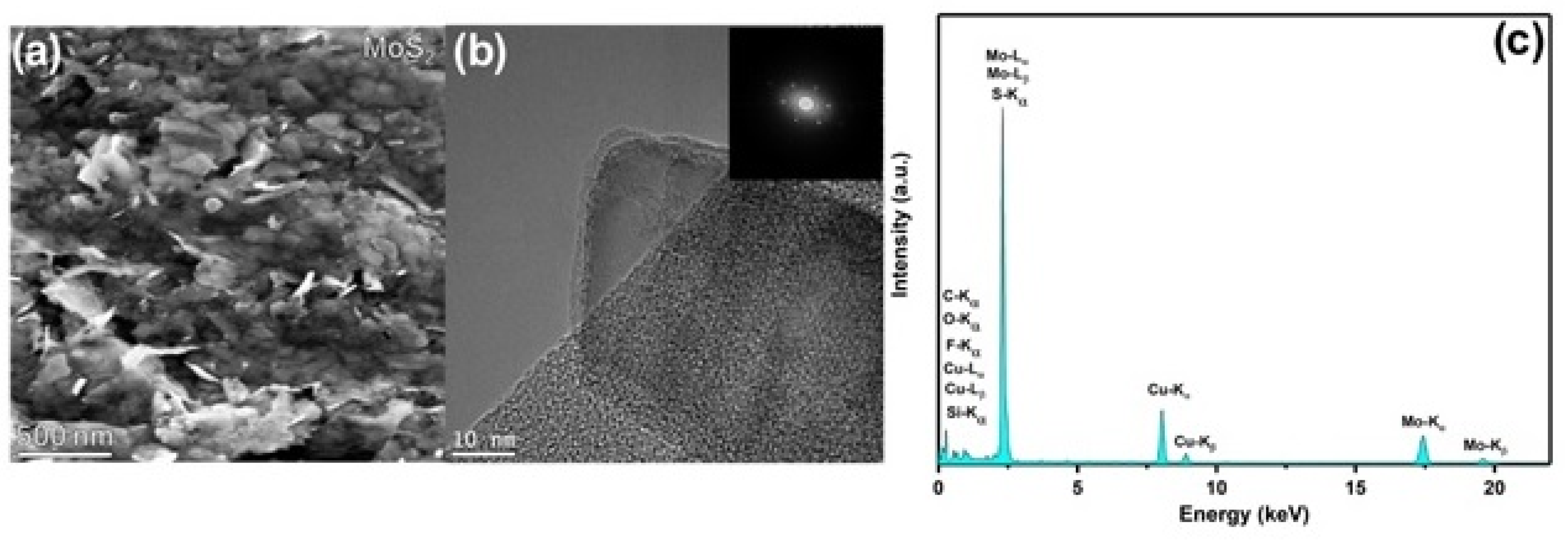
2.2. Preparation of 2D MoS2 Nanosheets

2 g of MoS2 powder were added to 40 mL of N-methyl-2-pyrrolidone (NMP), and a probe sonic tip was used to sonicate the solution for a certain number of hours (power: 60% amplitude). The sonic tip was pulsed for 6 s on and 2 s off to avoid damage to the processor and reduce solvent heating, and thus, degradation. The beaker was connected to a cooling system that allowed for cold water (under 5 °C) to flow around the dispersion during sonication. Then, exfoliated MoS2 nanosheets in NMP solvent were centrifuged at high spin rate (10,000 rpm) to obtain the MoS2 nanoflakes. Then, these MoS2 nanosheets were redispersed in DMF through bath sonication in a concentration of 0.08 mg mL−1. This solution was then used for the different additions to perovskite precursor solutions.

2.3. Preparation of the Perovskite Precursors Solutions

All the perovskite precursor solutions were prepared in a N2-filled glovebox. The MAPbI3 perovskite solutions were prepared by mixing methylammonium iodide (MAI, 159 mg) and lead (II) iodide (PbI2, 461 mg) in a mixture of N,N-dimethylformamide (DMF, 629 µL) and dimethyl sulfoxide (DMSO, 71 µL). The CsMAFAPbIBr perovskite precursors solutions were prepared by mixing formamidinium iodide (FAI, 172 mg), lead (II) iodide (PbI2, 507 mg), lead (II) bromide (PbBr2, 73 mg), methylammonium bromide (MABr, 22 mg) and cesium iodide (CsI, 17 mg) in a mixture of N,N-dimethylformamide (DMF, 900 µL) and dimethyl sulfoxide (DMSO, 100 µL). 2D MoS2 nanosheets dispersion in DMF was added into perovskite precursor solutions at different volume ratios (5%, 10%, 20%), keeping the DMF/DMSO volume ratio constant.

2.4. Photovoltaic Device Fabrication

Perovskite solar cell architectures are shown in Figure 1a,b. ITO-coated glass substrates were cleaned by ultrasonication in a deionized water, acetone, 2-propanol. Polytriarylamine (PTAA) layer (1.5 mg mL−1 in toluene) was deposited by spin coating at 6000 rpm for 30 s and annealed at 100 °C for 10 min. The rest of the processes were performed in an N2-filled glovebox. The MAPbI3 perovskite precursor solution was spin coated onto PTAA coated ITO substrates at 4000 rpm for 25 s; for solvent dripping, 200 µL of toluene was dropped onto the film 15 s prior to the end. The CsMAFAPbIBr perovskite precursor solution was spin coated onto PTAA coated ITO substrates by a consecutive two-step spin coating process at 1000 rpm and 6000 rpm for 10 s and 20 s, respectively; for solvent dripping, 200 µL of chlorobenzene was dropped onto the film 5 s prior to the end. The perovskite film was then annealed for 10 min at 100 °C and then allowed to cool down to room temperature. Then, a PCBM solution in chlorobenzene (25 mg mL−1) was spin coated onto the perovskite layer at 1000 rpm for 60 s. Finally, a BCP solution in 2-propanol (0.5 mg mL−1) was spin coated at 6000 rpm for 20 s. Solar cell devices are completed by thermal evaporation of 100 nm Al electrodes.

2.5. Materials Characterization

The scanning electron microscopy (SEM) imaging was performed by a MERLIN Zeiss SEM FEG instrument at an accelerating voltage of 5 kV, using an in-lens detector. The particle size distribution was estimated using the open-source ImageJ software, by measuring the major axis of 100 perovskite grains for each sample. HRTEM images were acquired on an FEI Titan (Thermo Fisher Scientific Inc., Waltham, MA, USA) operating at an acceleration voltage of 300 keV. The EDX spectrum of the MoS2 dispersion was acquired on Jeol2100 (Jeol Ltd., Akishima, Tokyo, Japan) operating at 200 keV and equipped with an Oxford Instruments 80mm2 silicon drift detector with a 10° holder tilt. Ultraviolet–visible (UV-Vis) absorption spectra were measured on PerkinElmer (Lambda 1050, Waltham, MA, USA) spectrophotometer in the 300–800 nm wavelength range at room temperature. Steady-state and time-resolved photoluminescence (PL) was performed using an Edinburgh FLS920 spectrometer (Edinburgh Instruments, Scotland, UK) equipped with a Peltier-cooled Hamamatsu R928 photomultiplier tube (185–850 nm). An Edinburgh Xe900 450 W Xenon arc lamp (Edinburgh Instruments, Scotland, UK) was employed as the exciting light source. Emission lifetimes were determined using the single photon counting technique by means of the same Edinburgh FLS980 spectrometer (Edinburgh Instruments, Scotland, UK) using a laser diode as the excitation source and a Hamamatsu MCP R3809U-50 as detector.

2.6. Photovoltaic Device Characterization

The devices were characterized in an N2 atmosphere by using a Keithley 2400 Source Measure Unit (Tektronix, Berkshire, UK) and AirMass 1.5 Global (AM1.5G) solar simulator (Newport 91160A, Irvine, CA, USA) under an irradiation intensity of 100 mW cm−2. Current–voltage characteristics were acquired at voltages ranging from 1.2V to −0.2 V. The step voltage is fixed at 10 mV and the delay time to 100 ms.

3. Results and Discussion

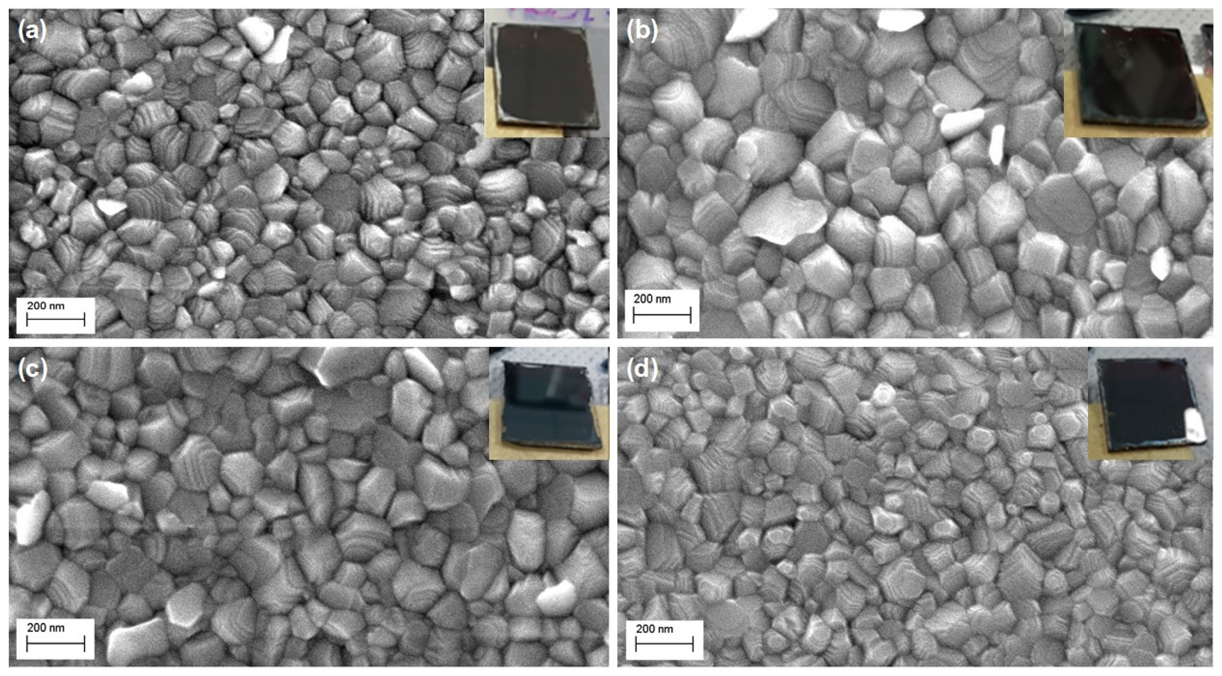
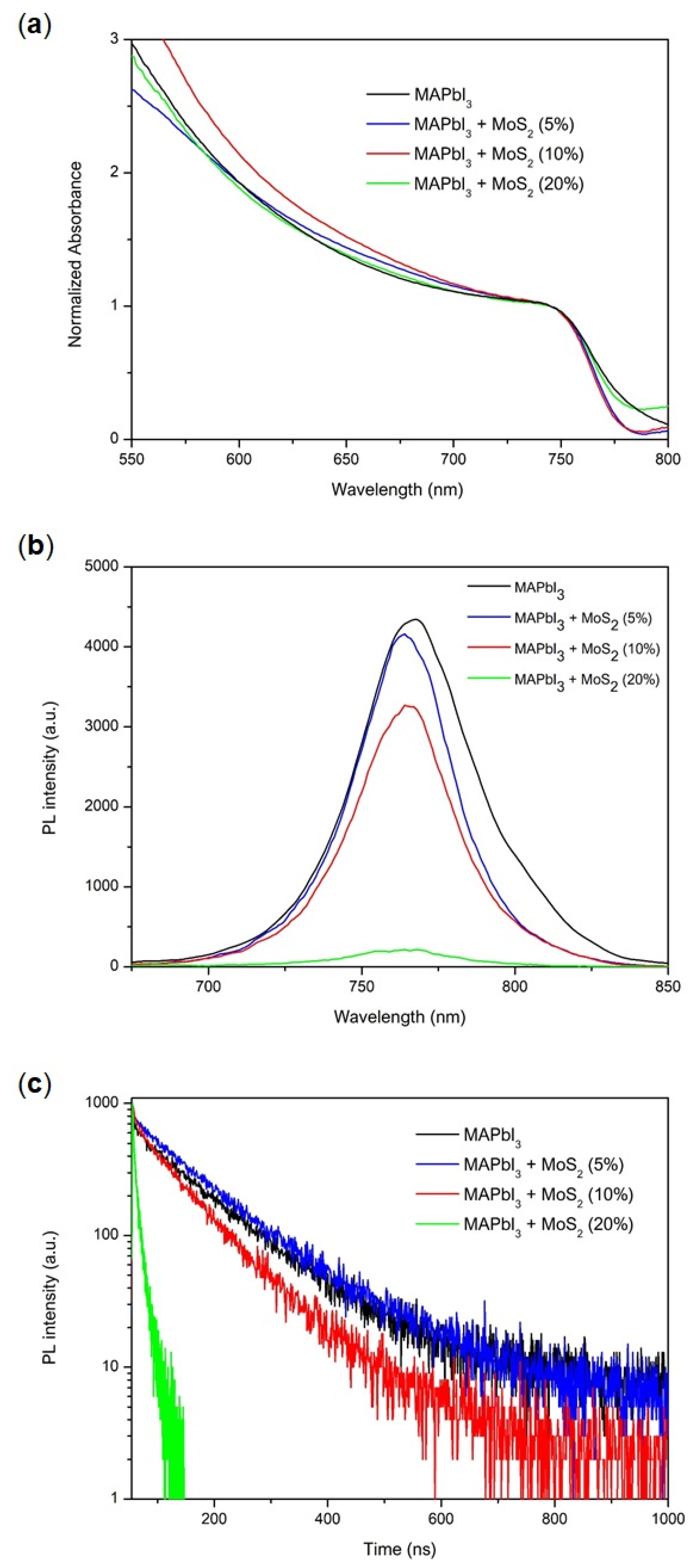
3.1. Properties and Characterizations of Materials

The MoS2 nanosheets used in this work as an additive in hybrid halide perovskite solutions were prepared by liquid-phase exfoliation (see experimental section). Firstly, the 2D material was characterized in order to confirm an effective exfoliation. The scanning electron microscopy (SEM, Figure 2a) image shows few-layered MoS2 nanoflakes. High-resolution TEM (HRTEM, Figure 2b) and its corresponding fast Fourier transform (FFT, inset of Figure 2b) pattern reveal the highly crystalline structure of the as exfoliated MoS2 material. Moreover, the exfoliated flakes reveal well-defined edges and no apparent damage in the basal planes, suggesting that the obtained material is of high quality.
In the EDX spectrum (Figure 2c), the molybdenum (Mo) and sulphur (S) peaks are clearly present confirming the identity of the nanosheets. The carbon (C) peak is also clearly identifiable and attributable to both the lacey carbon grid, as well as to possible residual DMF solvent. Additional peaks can be attributed to the background scattered signal (iron (Fe) and chromium (Cr)) from the TEM polepieces. Copper (Cu) peaks are present due to the copper TEM grid. The silicon (Si) peak is due to an EDX spectral artefact, being most probably attributable to an internal fluorescence peak from the silicon window on the drift detector.
The as-obtained MoS2 sheets were dispersed in N,N-dimethylformamide and employed as an additive for MAPbI3 perovskite precursor solution at different volume ratios: 5, 10, 20 (%, V/V). A preliminary check on the compatibility between MoS2 TMD sheets and the reaction environment in which the nucleation and growth processes of the perovskite material take place confirmed the possibility of using this material as an additive for perovskite precursor solutions. In this environment, reasonably good solubility of the TMD is observed, and no precipitation or phase separation occur during the spin coating process. This high solubility can be explained by the coordinated equilibrium of lead cations and iodide ions present in the perovskite precursor solution along with MoS2 [31]. Indeed, the S nonbonding lone-pair orbital can function as an electron donor (Lewis base), interacting with lead cations (Lewis acids) in solution, while halide ions can strongly coordinate molybdenum [32]. The resulting films are spin coated on glass/ITO/polytriarylamine (PTAA), which is the hole transporting material employed in the solar cell architecture. These films are smooth, particularly homogeneous and pinhole-free (insets of Figure 3). The thickness of the perovskite films was found to slightly increase upon the addition of MoS2 sheets (Table 1). Small differences among the three samples are within experimental error.
SEM images (Figure 3b,c) show the MoS2 additive’s influence on the MAPbI3 perovskite grain size: the addition of the additive into the perovskite precursor solutions, at low–intermediate concentrations (5% and 10%), results in the formation of larger grains. The particle size analysis of these images (Figure 4, Table 2) reveals a significant increase indeed in the average grain size, from 116 nm for the pristine sample to 177 nm and 187 nm for the MoS2 (5%) and MoS2 (10%) perovskite samples, respectively. Moreover, the 10% MoS2 additive sample has the narrowest grain size distribution, with more than 50% of particles located in a small range from 160 nm to 220 nm. The implication of this observation is a reduced extension of the grain boundary region. This prefigures a reduced charge loss, typically occurring at the grain boundary region, giving rise to an improvement in final device performance.
There are several factors that can affect the perovskite’s morphology, including the intrinsic properties of the material itself, the deposition method, the presence of impurities, the surface energy of the substrate, and the application of post-treatments [31]. The MoS2 additive seems to be able to regulate film morphology by acting upon the crystal growth and by altering the colloid distribution in the perovskite precursors [31]. This results in high-quality, pinhole-free perovskite films with larger grain size and filled grain boundaries [33,34]. Since the crystal growth rate is relatively fast and is a function of solution supersaturation, reaching a high nucleation rate before the onset of crystal growth is required to improve perovskite film coverage. The heterogeneous nucleation mechanism in addition provides fewer nucleation sites, when compared to homogeneous nucleation, leading to the formation of larger crystalline domains [34,35]. This interesting observation is extended here to the deposition of perovskite onto organic PTAA substrates, showing that TMDs can also affect this kind of device, which would be ideally suited for flexible, light, and portable PSCs. Noticeably, at 20% MoS2 additive concentration, the effect on the grain size is lost as these films exhibit similar grain sizes and particle size distribution to pristine perovskite (Figure 4, Table 2). The effect of such high MoS2 concentration is ascribed to an increased number of heterogeneous nucleation sites that would impair the formation of large grains during the perovskite crystal growth. This is suggested by the SEM image in Figure 3d. A morphology characterized by smaller grains, such as the one recorded for the 20% MoS2 additive perovskite film, is in general associated with poor charge transport and collection in PSCs, which are limited by inter-grain boundary recombination losses [36].
The approach reported in this work was extended to mixed cation–halide CsMAFAPbIBr perovskite, which is among the best-performing perovskite material for solar cells. Surprisingly, we found that the inclusion of MoS2 additive into the triple-cation did not significantly affect the final morphology of the perovskite films (Figure 5), as all the samples exhibited a uniform and compact surface with similar grain size distribution (Figure 6, Table 3). This can mainly be ascribed to the marginal role of the additive in influencing and controlling the crystallization dynamics of the CsMAFAPbIBr perovskite material. We suppose that in this case, the lower-solubility cesium salts act as heterogeneous nucleation seeds, promoting heterogenic crystal growth [35].
UV-Vis absorption spectra of the perovskite thin films are shown in Figure 7a. Both pristine MAPbI3 and MAPbI3:MoS2 films show the same absorption onset. MoS2 TMD additive, as expected, does not contribute to the absorption spectra due to the high extinction coefficient of perovskite material and due to low additive concentration. Conversely, steady-state photoluminescence (PL, Figure 7b) revealed that the MoS2 inclusion causes PL quenching, and this is more pronounced at high additive concentrations. We also observed a very small blue shift of the PL band upon additive addition, probably due to a surface and/or grain boundary trap-states passivation effect. The PL quenching observed is a consequence of an enhanced charge transfer from the perovskite structure to the MoS2 TMD sheets. This is in line with what has previously been observed on alternative systems [37,38] and is related to the optimal band gap alignment and carrier dynamics for these two materials. Moreover, the mechanism of high carrier transfer efficiency among these heterostructures involves both holes and electrons, leading to an improvement in device performance [38] through an intelligently designed charge funneling mechanism. The time-resolved photoluminescence (TRPL) decay (Figure 7c) is consistent with this picture, as the charge carrier lifetime (τav) [39] decreases with increasing MoS2 content, from 120 ns for the pristine MAPbI3 perovskite to 9 ns for the 20% MoS2 additive perovskite.

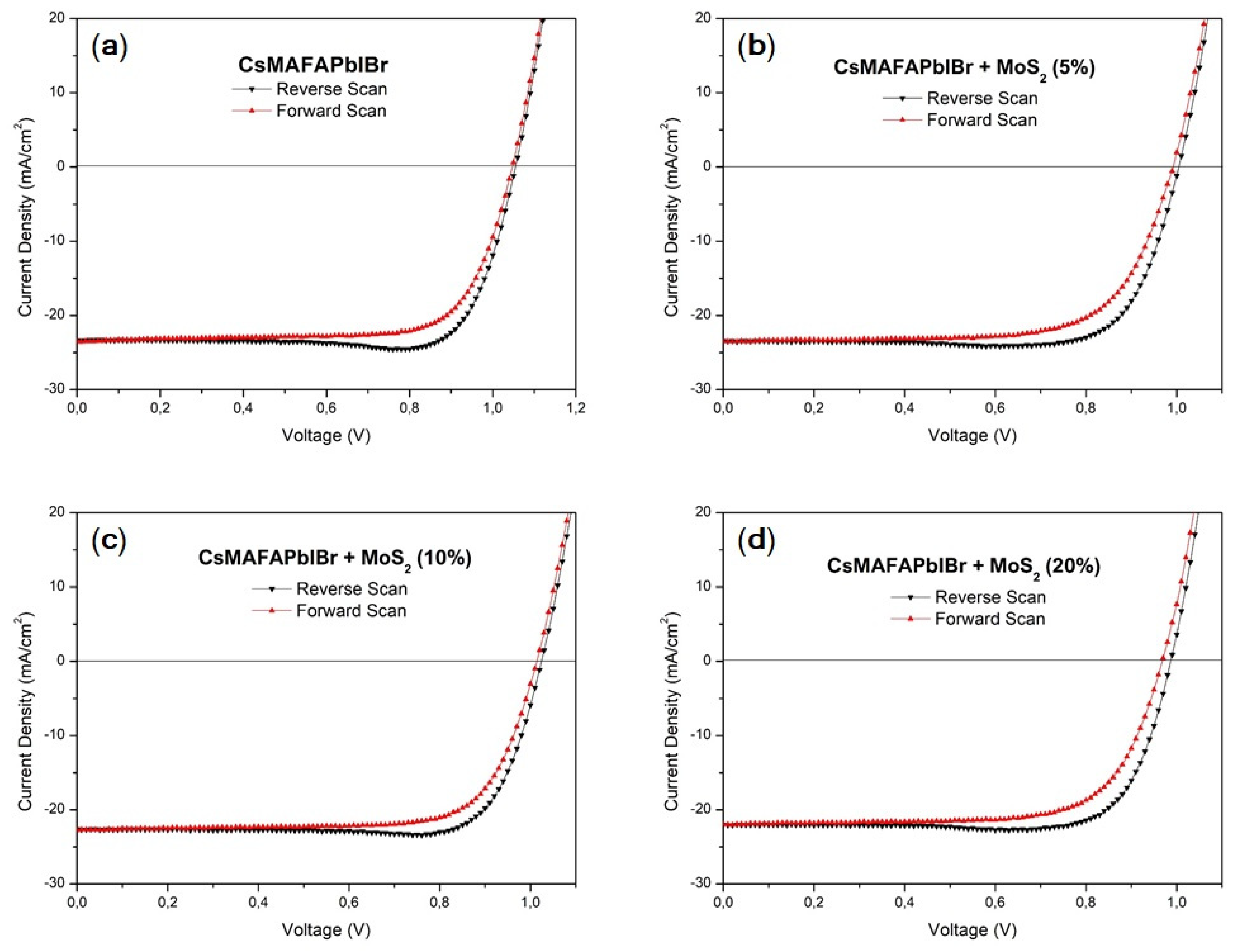
3.2. Photovoltaic Performances

Perovskite films with and without MoS2 additive were included in p-i-n solar cell architectures, as shown in Figure 1. Perovskite solar cells bearing this layout have advantages over n-i-p ones because of the possibility of low-temperature preparation and negligible J-V hysteresis effects [40]. Additionally, the reasons for the selection of PTAA as the hole transporting layer include increased resilience to the negative effects of oxygen and moisture due to its hydrophobicity, and remarkable intrinsic hole mobility [41]. Figure 8 and Table 4 display the J-V curves and the photovoltaic performances of the MAPbI3 material. The J-V characteristics indicate that MoS2 sheets as an additive improve device properties. The best PCE of 17.4% was recorded for the 10% MoS2 additive PSC (FF = 68.9%, VOC = 1.02 V, JSC = 24.76 mA/cm2); however, even at low concentration (5%), the inclusion of MoS2 additive leads to better performance (16.0%) with respect to the pristine MAPbI3 device (15.1%). These findings are consistent with the morphological characterization, for which low and intermediate additive concentrations enable us to obtain larger grain sizes, and therefore reduced grain boundary recombination. The JSC shows no significant change with additive modification, and thus the increment in PCE is mainly related to the enhanced VOC. The VOC improvement could be a consequence of suppressed non-radiative recombination processes within the structure, which occur in the absorber layer and at the interfaces between the perovskite and the transporting layers [42]. On the other hand, for higher MoS2 additive concentration (20%), the PCE significantly drops to 13.3%. Adding an excess of MoS2 TMD sheets can lead to the formation of a poor-quality perovskite layer, which can be attributed to aggregated MoS2 nanosheets impairing perovskite growth [43], resulting in shorter diffusion lengths of photogenerated carriers, higher density of trap states, and high carrier recombination rates. This is an indirect proof of how important it is for MoS2 sheets to be well exfoliated, and thus well isolated, rather than in a bulky or aggregated phase. Decreased performance of the 20% MoS2 PSC is in good agreement with the photoluminescence measurements that showed the almost completely quenched PL signal at higher additive concentrations (20%).
On the other hand, the photovoltaic performance of mixed cation–halide CsMAFAPbIBr PSCs (Figure 9, Table 5) implemented in an identical device architecture, reported in Figure 1b, did not show any significant change following the MoS2 inclusion. PCE of the best device was above 18%, VOC was between 1.01 and 1.03 V, FF was above 78%, and JSC was above 23 mA/cm2 for the pristine perovskite and CsMAFAPbIBr:MoS2 (5%). For MoS2 (10%) and MoS2 (20%), JSC slightly decreases to 22.62 and 22.08 mA/cm2, respectively, possibly due to the occurrence of some nanosheet aggregation as observed for MAPbI3. It should be noted, however, that these differences are negligible if we consider a similar mean value and statistical distribution, which reflects the negligible differences in film morphologies (Figure 5) observed with and without MoS2.

4. Conclusions

In summary, we demonstrated an effective additive-engineering approach to improve the morphology of perovskite films grown on an organic substrate, leading to superior device performance. Liquid-phase exfoliated molybdenum disulfide sheets were employed as an additive in MAPbI3 perovskite precursor solution, to measure their effect at diverse concentrations and upon diverse precursor formulations. Our findings suggest that MoS2 incorporation (10% V/V) into a MAPbI3 perovskite photoactive layer results in high-quality films with larger grains and optimized morphology, suitable for device integration. As a result, the champion device yields a remarkable PCE of 17.4%, 15% higher than the undoped device. The beneficial impact of 2D layered materials originates from seed induced heterogeneous nucleation, resulting in superior perovskite film morphology, and therefore in high-performance PSCs. Conversely, for the mixed cation–halide perovskite, no improvements were observed with the addition of the additive to the precursor ink. Our results confirm that the nucleation process differs for distinct perovskite precursor compositions, and so, that the process is influenced differently by the presence of additives. These results contribute to the development of perovskite-based solar cells and, more specifically, to the wide research front focused on controlling photoactive film deposition and growth.

Author Contributions

Conceptualization, J.C. and A.L.; methodology, A.L., A.R. and S.C. (Silvia Colella); formal analysis, N.T., G.B., S.C. (Sonia Carallo), M.L., D.S., O.R., V.N. and G.G.; investigation, N.T., A.L., A.R., G.B., M.L., D.S. and O.R.; data curation, N.T.; writing—original draft preparation, N.T., D.S., J.C., A.L. and A.R.; writing—review and editing, N.T., D.S., J.C., A.L. and A.R.; supervision, J.C., A.L. and A.R. All authors have read and agreed to the published version of the manuscript.

Funding

This work was supported by the ERC 3D2DPrint CoG Grant. This publication emanated from research supported in part by a grant from Science Foundation Ireland under Grant number 12/RC/2278 P2. This work was founded by the project Best4U—“Tecnologia per celle solari bifacciali ad alta Efficienza a 4 terminali per utility scale”, of the Italian Ministry of University and Scientific Research (MIUR), Bando PON R&I 2014–2020 e FSC “Avviso per la presentazione di Progetti di Ricerca Industriale e Sviluppo Sperimentale nelle 12 aree di Specializzazione individuate dal PNR 2015–2020”—decreto concessione agevolazione protocollo 991 del 21 maggio 2019 MIUR (Contract number: PON ARS01_00519; CUP B88D19000160005). The authors are grateful to the “Progetto Tecnopolo per la Medicina di precisione, Deliberazione della Giunta Regionale n. 2117 del 21 November 2018”.

Data Availability Statement

Data are fully available upon request.

Acknowledgments

V.N. wishes to thank the support from the ERC 3D2DPrint CoG Grant. The authors gratefully acknowledge the project Best4U—“Tecnologia per celle solari bifacciali ad alta Efficienza a 4 terminali per utility scale”. The authors are grateful to the “Progetto Tecnopolo per la Medicina di precisione, Deliberazione della Giunta Regionale n. 2117 del 21 November 2018”.

Conflicts of Interest

The authors declare no conflict of interest.

References

  1. Chi, W.; Banerjee, S.K. Progress in materials development for the rapid efficiency advancement of perovskite solar cells. Small 2020, 16, 1907531. [Google Scholar] [CrossRef]
  2. Kim, J.Y.; Lee, J.W.; Jung, H.S.; Shin, H.; Park, N.G. High-efficiency perovskite solar cells. Chem. Rev. 2020, 120, 7867–7918. [Google Scholar] [CrossRef]
  3. Fu, Y.; Zhu, H.; Chen, J.; Hautzinger, M.P.; Zhu, X.-Y.; Jin, S. Metal halide perovskite nanostructures for optoelectronic applications and the study of physical properties. Nat. Rev. Mater. 2019, 4, 169–188. [Google Scholar] [CrossRef]
  4. Ann, M.H.; Kim, J.; Kim, M.; Alosaimi, G.; Kim, D.; Ha, N.Y.; Seidel, J.; Park, N.; Yun, J.S.; Kim, J.H. Device design rules and operation principles of high-power perovskite solar cells for indoor applications. Nano Energy 2020, 68, 104321. [Google Scholar] [CrossRef]
  5. Tailor, N.K.; Kim, J.; Kim, M.; Alosaimi, G.; Kim, D.; Ha, N.Y.; Seidel, J.; Park, N.; Yun, J.S.; Kim, J.H. Recent progress in morphology optimization in perovskite solar cell. J. Mater. Chem. A 2020, 8, 21356–21386. [Google Scholar] [CrossRef]
  6. Kim, H.S.; Hagfeldt, A.; Park, N.G. Morphological and compositional progress in halide perovskite solar cells. Chem. Commun. 2019, 55, 1192–1200. [Google Scholar] [CrossRef] [PubMed]
  7. Arain, Z.; Liu, C.; Yang, Y.; Mateen, M.; Ren, Y.; Ding, Y.; Liu, X.; Ali, Z.; Kumar, M.; Dai, S. Elucidating the dynamics of solvent engineering for perovskite solar cells. Sci. China Mater. 2019, 62, 161–172. [Google Scholar] [CrossRef] [Green Version]
  8. Park, N.G. Research direction toward scalable, stable, and high efficiency perovskite solar cells. Adv. Energy Mater. 2020, 10, 1903106. [Google Scholar] [CrossRef]
  9. Al-Asbahi, B.A.; Qaid, S.M.H.; Hezam, M.; Bedja, I.; Ghaithan, H.M.; Aldwayyan, A.S. Effect of deposition method on the structural and optical properties of CH3NH3PbI3 perovskite thin films. Opt. Mater. 2020, 103, 109836. [Google Scholar] [CrossRef]
  10. Mahapatra, A.; Mahapatra, A.; Prochowicz, D.; Tavakolic, M.M.; Trivedi, S.; Kumar, P.; Yadav, P. A review of aspects of additive engineering in perovskite solar cells. J. Mater. Chem. A 2020, 8, 27–54. [Google Scholar] [CrossRef]
  11. Masi, S.; Rizzo, A.; Munir, R.; Listorti, A.; Giuri, A.; Corcione, C.E.; Treat, N.D.; Gigli, G.; Amassian, A.; Stingelin, N.; et al. Organic Gelators as Growth Control Agents for Stable and Reproducible Hybrid Perovskite-Based Solar Cells. Adv. Energy Mater. 2017, 7, 1602600. [Google Scholar] [CrossRef] [Green Version]
  12. Masi, S.; Sestu, N.; Valenzano, V.; Higashino, T.; Imahori, H.; Saba, M.; Bongiovanni, G.; Armenise, V.; Milella, A.; Gigli, G.; et al. Simple processing additive-driven 20% efficiency for inverted planar heterojunction perovskite solar cells. ACS Appl. Mater. Interfaces 2020, 12, 18431–18436. [Google Scholar] [CrossRef]
  13. Giuri, A.; Masi, S.; Listorti, A.; Gigli, G.; Colella, S.; Corcione, C.E.; Rizzo, A. Polymeric rheology modifier allows single-step coating of perovskite ink for highly efficient and stable solar cells. Nano Energy 2018, 54, 400–408. [Google Scholar] [CrossRef]
  14. Masi, S.; Masi, S.; Rizzo, A.; Aiello, F.; Balzano, F.; Uccello-Barretta, G.; Listorti, A.; Gigliac, G.; Colella, S. Multiscale morphology design of hybrid halide perovskites through a polymeric template. Nanoscale 2015, 7, 18956–18963. [Google Scholar] [CrossRef] [PubMed]
  15. Jeong, J.; Kim, M.; Seo, J.; Lu, H.; Ahlawat, P.; Mishra, A.; Yang, Y.; Hope, M.A.; Eickemeyer, F.T.; Kim, M. Pseudo-halide anion engineering for α-FAPbI3 perovskite solar cells. Nature 2021, 592, 381–385. [Google Scholar] [CrossRef] [PubMed]
  16. You, P.; Tang, G.; Cao, J.; Shen, D.; Ng, T.; Hawash, Z.; Wang, N.; Liu, C.; Lu, W.; Tai, Q. 2D materials for conducting holes from grain boundaries in perovskite solar cells. Light Sci. Appl. 2021, 10, 68. [Google Scholar] [CrossRef] [PubMed]
  17. Masi, S.; Aiello, F.; Listorti, A.; Balzano, F.; Altamura, D.; Giannini, C.; Caliandro, R.; Uccello-Barretta, G.; Rizzo, A.; Colella, S. Connecting the solution chemistry of PbI2 and MAI: A cyclodextrin-based supramolecular approach to the formation of hybrid halide perovskites. Chem. Sci. 2018, 9, 3200–3208. [Google Scholar] [CrossRef] [PubMed] [Green Version]
  18. Mastria, R.; Colella, S.; Qualtieri, A.; Listorti, A.; Gigliab, G.; Rizzo, A. Elucidating the effect of the lead iodide complexation degree behind the morphology and performance of perovskite solar cells. Nanoscale 2017, 9, 3889–3897. [Google Scholar] [CrossRef]
  19. Chen, H.-C.; Lan, J.M.; Hsu, H.L.; Li, C.W.; Shieh, T.S.; Wong, K.T.; Chen, C.P. Synergistic improvements in performance and stability of inverted planar MAPbI3 based perovskite solar cells incorporating benzylammonium halide salt additives. Mater. Chem. Front. 2021, 5, 3378–3387. [Google Scholar] [CrossRef]
  20. Liu, Z.; Ono, L.K.; Qi, Y. Additives in metal halide perovskite films and their applications in solar cells. J. Energy Chem. 2020, 46, 215–228. [Google Scholar] [CrossRef]
  21. Haque, F.; Wright, M.; Mahmud, M.A.; Yi, H.; Wang, D.; Duan, L.; Xu, C.; Upama, M.B.; Uddin, A. Effects of hydroiodic acid concentration on the properties of CsPbI3 perovskite solar cells. ACS Omega 2018, 3, 11937–11944. [Google Scholar] [CrossRef] [PubMed] [Green Version]
  22. Ferguson, V.; Silva, S.R.P.; Zhang, W. Carbon materials in perovskite solar cells: Prospects and future challenges. Energy Environ. Mater. 2019, 2, 107–118. [Google Scholar] [CrossRef] [Green Version]
  23. You, P.; Tang, G.; Yan, F. Two-dimensional materials in perovskite solar cells. Mater. Today Energy 2019, 11, 128–158. [Google Scholar] [CrossRef]
  24. Bati, A.S.R.; Batmunkh, M.; Shapter, J.G. Emerging 2D layered materials for perovskite solar cells. Adv. Energy Mater. 2020, 10, 1902253. [Google Scholar] [CrossRef]
  25. Carlo, A.; Di Agresti, A.; Brunetti, F.; Pescetelli, S. Two-dimensional materials in perovskite solar cells. J. Phys. Energy 2020, 2, 128–158. [Google Scholar] [CrossRef]
  26. Kakavelakis, G.; Gouda, L.; Tischler, Y.; Kaliakatsos, I.; Petridis, K. 2D Transition Metal. Dichalcogenides for Solution-Processed Organic and Perovskite Solar Cells; Springer: Berlin/Heidelberg, Germany, 2019. [Google Scholar]
  27. Capasso, A.; Matteocci, F.; Najafi, L.; Prato, M.; Buha, J.; Cinà, L.; Pellegrini, V.; di Carlo, A.; Bonaccorso, F. Few-Layer MoS2 Flakes as Active Buffer Layer for Stable Perovskite Solar Cells. Adv. Energy Mater. 2016, 6, 1600920. [Google Scholar] [CrossRef]
  28. Huang, P.; Chen, Q.; Zhang, K.; Yuan, L.; Zhou, Y.; Song, B.; Li, Y. 21.7% efficiency achieved in planar n-i-p perovskite solar cells via interface engineering with water-soluble 2D TiS2. J. Mater. Chem. A 2019, 7, 6213–6219. [Google Scholar] [CrossRef]
  29. Liang, M.; Ali, A.; Belaidi, A.; Hossain, M.I.; Ronan, O.; Downing, C.; Tabet, N.; Sanvito, S.; I-Mellouhi, F.E.; Nicolosi, V. Improving stability of organometallic-halide perovskite solar cells using exfoliation two-dimensional molybdenum chalcogenides. NPJ 2D Mater. Appl. 2020, 4, 40. [Google Scholar] [CrossRef]
  30. Liu, Z.; Liu, K.; Zhang, F.; Jain, S.M.; He, T.; Jiang, Y.; Yuan, M. CH3NH3PbI3:MoS2 heterostructure for stable and efficient inverted perovskite solar cell. Sol. Energy 2020, 195, 436–445. [Google Scholar] [CrossRef]
  31. Vasilopoulou, M.; Fakharuddin, A.; Coutsolelos, A.G.; Falaras, P.; Argitis, P.; Yusoffd, A.R.B.M.; Nazeeruddin, M.K. Molecular materials as interfacial layers and additives in perovskite solar cells. Chem. Soc. Rev. 2020, 49, 4496–4526. [Google Scholar] [CrossRef]
  32. Bermudez, V.M. Theoretical study of the adsorption of Lewis acids on MoS2 in relation to atomic layer deposition of Al2O3. J. Vac. Sci. Technol. A 2020, 38, 062412. [Google Scholar] [CrossRef]
  33. Zhang, Y.; Tan, L.; Fu, Q.; Chen, L.; Ji, T.; Hu, X.; Chen, Y. Enhancing the grain size of organic halide perovskites by sulfonate-carbon nanotube incorporation in high performance perovskite solar cells. Chem. Commun. 2016, 52, 5674–5677. [Google Scholar] [CrossRef]
  34. Liu, C.; Cheng, Y.B.; Ge, Z. Understanding of perovskite crystal growth and film formation in scalable deposition processes. Chem. Soc. Rev. 2020, 49, 1653–1687. [Google Scholar] [CrossRef]
  35. Ke, L.; Luo, S.; Ren, X.; Yuan, Y. Factors influencing the nucleation and crystal growth of solution-processed organic lead halide perovskites: A review. J. Phys. D Appl. Phys. 2021, 54, 163001. [Google Scholar] [CrossRef]
  36. Li, H.; Wu, G.; Li, W.; Zhang, Y.; Liu, Z.; Wang, D.; Liu, S. Additive Engineering to Grow Micron-Sized Grains for Stable High Efficiency Perovskite Solar Cells. Adv. Sci. 2019, 6, 1901241. [Google Scholar] [CrossRef] [Green Version]
  37. Sheng, Y.; Shang, Q.; Zhao, L.; Wang, R.; Zhang, Z.; Yang, P.; Sui, X.; Qiu, X.; Liu, X.; Zhang, Q.; et al. Highly Efficient Charge Transfer between Perovskite Nanocrystals and g-C3N4 Nanosheets. Phys. Status Solidi Basic Res. 2020, 257, 1655–1662. [Google Scholar]
  38. Fang, Q.; Shang, Q.; Zhao, L.; Wang, R.; Zhang, Z.; Yang, P.; Sui, X.; Qiu, X.; Liu, X.; Zhang, Q.; et al. Ultrafast charge transfer in perovskite nanowire/2D transition metal dichalcogenide heterostructures. J. Phys. Chem. Lett. 2018, 9, 1655–1662. [Google Scholar] [CrossRef]
  39. Lakowicz, J.R. Principles of Fluorescence Spectroscopy; Springer: Berlin/Heidelberg, Germany, 2006. [Google Scholar]
  40. Meng, L.; You, J.; Guo, T.F.; Yang, Y. Recent advances in the inverted planar structure of perovskite solar cells. Acc. Chem. Res. 2016, 49, 155–165. [Google Scholar] [CrossRef] [PubMed]
  41. Zhao, Q.; Wu, R.; Zhang, Z.; Xiong, J.; He, Z.; Fan, B.; Zhang, J. Achieving efficient inverted planar perovskite solar cells with nondoped PTAA as a hole transport layer. Org. Electron. 2019, 71, 106–112. [Google Scholar] [CrossRef]
  42. Wang, Y.; Wang, S.; Chen, X.; Li, Z.; Wang, J.; Lia, T.; Deng, X. Largely enhanced: VOC and stability in perovskite solar cells with modified energy match by coupled 2D interlayers. J. Mater. Chem. A 2018, 6, 4860–4867. [Google Scholar] [CrossRef]
  43. Wu, W.Q.; Yang, Z.; Rudd, P.N.; Shao, Y.; Dai, X.; Wei, H.; Huang, J. Bilateral alkylamine for suppressing charge recombination and improving stability in blade-coated perovskite solar cells. Sci. Adv. 2019, 5. [Google Scholar] [CrossRef] [Green Version]
Figure 1. (a) Schematic p-i-n architectures of the MAPbI3:MoS2 and (b) CsMAFAPbIBr:MoS2 PSCs.
Nanomaterials 11 01706 g001
Figure 2. (a) SEM image. (b) High-resolution TEM images of exfoliated MoS2, inset in (b) is the fast Fourier transform pattern of exfoliated MoS2. (c) The EDX spectrum confirms the identity of the nanosheets.
Nanomaterials 11 01706 g002
Figure 3. Top-view SEM images of the as-prepared MAPbI3 perovskite films, with and without MoS2 additive: (a) MAPbI3; (b) MAPbI3 + MoS2 (5%); (c) MAPbI3 + MoS2 (10%); (d) MAPbI3 + MoS2 (20%). In the insets are reported the photographs of the corresponding perovskite films coated on glass/ITO/PTAA substrates.
Nanomaterials 11 01706 g003
Figure 4. Particle size distribution histograms of the as-prepared MAPbI3 perovskite films, with and without MoS2 additive: (a) MAPbI3; (b) MAPbI3 + MoS2 (5%); (c) MAPbI3 + MoS2 (10%); (d) MAPbI3 + MoS2 (20%).
Nanomaterials 11 01706 g004
Figure 5. Top-view SEM images of the as-prepared CsMAFAPbIBr perovskite thin films, with and without MoS2 additive: (a) CsMAFAPbIBr; (b) CsMAFAPbIBr + MoS2 (5%); (c) CsMAFAPbIBr + MoS2 (10%); (d) CsMAFAPbIBr + MoS2 (20%).
Nanomaterials 11 01706 g005
Figure 6. Particle size distribution histograms of the as-prepared CsMAFAPbIBr perovskite films, with and without MoS2 additive: (a) CsMAFAPbIBr; (b) CsMAFAPbIBr + MoS2 (5%); (c) CsMAFAPbIBr + MoS2 (10%); (d) CsMAFAPbIBr + MoS2 (20%).
Nanomaterials 11 01706 g006
Figure 7. (a) UV-Vis, (b) steady-state photoluminescence (PL) and (c) time-resolved photoluminescence (TRPL) spectra of the MAPbI3 perovskite films, with and without MoS2 additive.
Nanomaterials 11 01706 g007
Figure 8. J-V curves of the MAPbI3 best-performing PSC: (a) MAPbI3; (b) MAPbI3 + MoS2 (5%); (c) MAPbI3 + MoS2 (10%); (d) MAPbI3 + MoS2 (20%).
Nanomaterials 11 01706 g008
Figure 9. J-V curves of the CsMAFAPbIBr best-performing PSC: (a) CsMAFAPbIBr; (b) CsMAFAPbIBr + MoS2 (5%); (c) CsMAFAPbIBr + MoS2 (10%); (d) CsMAFAPbIBr + MoS2 (20%).
Nanomaterials 11 01706 g009
Table 1. MAPbI3 film thicknesses, with and without MoS2 additive.
Average Thickness (nm)
MAPbI3422 ± 7
MAPbI3 + MoS2 (5%)439 ± 15
MAPbI3 + MoS2 (10%)436 ± 9
MAPbI3 + MoS2 (20%)442 ± 20
Table 2. Statistical analysis for the MAPbI3 grain size, with and without MoS2 additive.
Mean (nm)St. Dev. (nm)
MAPbI3116.3233.27
MAPbI3 + MoS2 (5%)177.1748.83
MAPbI3 + MoS2 (10%)187.5440.97
MAPbI3 + MoS2 (20%)125.6328.17
Table 3. Statistical analysis for the CsMAFAPbIBr grain size, with and without MoS2 additive.
Mean (nm)St. Dev. (nm)
CsMAFAPbIBr237.1771.32
CsMAFAPbIBr + MoS2 (5%)248.7470.56
CsMAFAPbIBr + MoS2 (10%)240.1072.42
CsMAFAPbIBr + MoS2 (20%)214.2369.25
Table 4. Photovoltaic characteristics of the MAPbI3 best-performing PSC and average values as well as standard deviations: reverse scan (black), forward scan (red).
FF (%)VOC (V)JSC (mA cm−2)PCE (%)
MAPbI367.4 (67.5 ± 1.8)
64.2 (66.9 ± 1.9)
0.91 (0.96 ± 0.04)
0.92 (0.96 ± 0.03)
24.49 (22.16 ± 1.65)
24.31 (22.20 ± 1.50)
15.09 (14.24 ± 0.60)
14.38 (14.20 ± 0.46)
MAPbI3 + MoS2 (5%)64.5 (60.1 ± 8.6)
63.3 (58.7 ± 7.8)
1.06 (1.05 ± 0.01)
1.05 (1.03 ± 0.02)
23.45 (22.37 ± 0.78)
23.48 (22.25 ± 0.86)
16.01 (14.13 ± 2.31)
15.54 (13.51 ± 2.36)
MAPbI3 + MoS2 (10%)68.9 (68.9 ± 1.1)
67.6 (67.5 ± 1.4)
1.02 (1.01 ± 0.01)
1.01 (1.00 ± 0.01)
24.76 (21.88 ± 2.05)
24.77 (21.91 ± 2.04)
17.42 (15.25 ± 1.55)
16.92 (14.85 ± 1.47)
MAPbI3 + MoS2 (20%)67.4 (71.1 ± 3.2)
63.7 (67.8 ± 3.9)
0.92 (0.92 ± 0.01)
0.91 (0.92 ± 0.01)
21.46 (19.75 ± 2.00)
21.44 (19.71 ± 2.01)
13.30 (12.88 ± 1.59)
12.45 (12.30 ± 1.60)
Table 5. Photovoltaic characteristics of the CsMAFAPbIBr best-performing PSC and average values as well as standard deviations: reverse scan (black), forward scan (red).
FF (%)VOC (V)JSC (mA cm−2)PCE (%)
CsMAFAPbIBr78.6 (78.4 ± 4.9)
68.8 (70.3 ± 4.0)
1.03 (1.03 ± 0.01)
1.00 (1.03 ± 0.01)
23.37 (21.38 ± 1.34)
23.56 (20.58 ± 0.69)
18.89 (17.29 ± 1.13)
16.97 (14.89 ± 0.90)
CsMAFAPbIBr + MoS2 (5%)78.2 (77.6 ± 4.8)
69.8 (70.6 ± 3.6)
1.01 (1.01 ± 0.03)
0.99 (1.01 ± 0.03)
23.47 (21.91 ± 1.66)
23.54 (21.86 ± 1.72)
18.45 (17.20 ± 1.19)
16.31 (15.45 ± 0.64)
CsMAFAPbIBr + MoS2 (10%)81.3 (78.5 ± 4.3)
73.5 (71.8 ± 3.2)
1.03 (1.01 ± 0.02)
1.01 (1.00 ± 0.02)
22.62 (22.41 ± 1.41)
22.76 (22.46 ± 1.32)
18.85 (17.78 ± 0.81)
16.98 (16.19 ± 0.58)
CsMAFAPbIBr + MoS2 (20%)78.8 (77.6 ± 3.2)
71.7 (70.7 ± 1.8)
1.01 (1.00 ± 0.02)
1.00 (0.99 ± 0.03)
22.08 (21.78 ± 0.76)
22.10 (21.81 ± 0.78)
17.59 (16.85 ± 0.63)
15.80 (15.21 ± 0.51)
Publisher’s Note: MDPI stays neutral with regard to jurisdictional claims in published maps and institutional affiliations.

