Advances in Quantum-Dot-Based Displays

 ,
,  , ,
, ,  , and
, and 
Abstract
1. Introduction
2. Micro-LED Display and QD Color-Conversion Technology
2.1. Background of Micro-LED Display
2.2. History of QD Patterning Technique
3. White-Light-Emitting Diode
3.1. CdSe QD-Based WLED
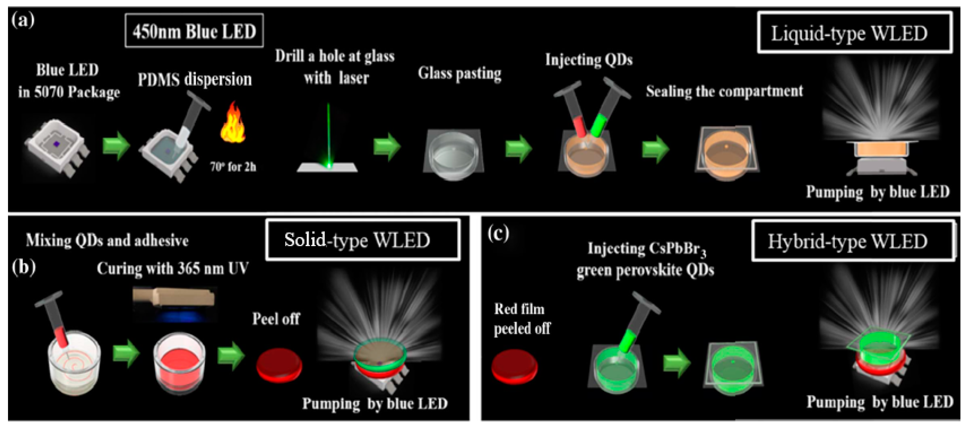
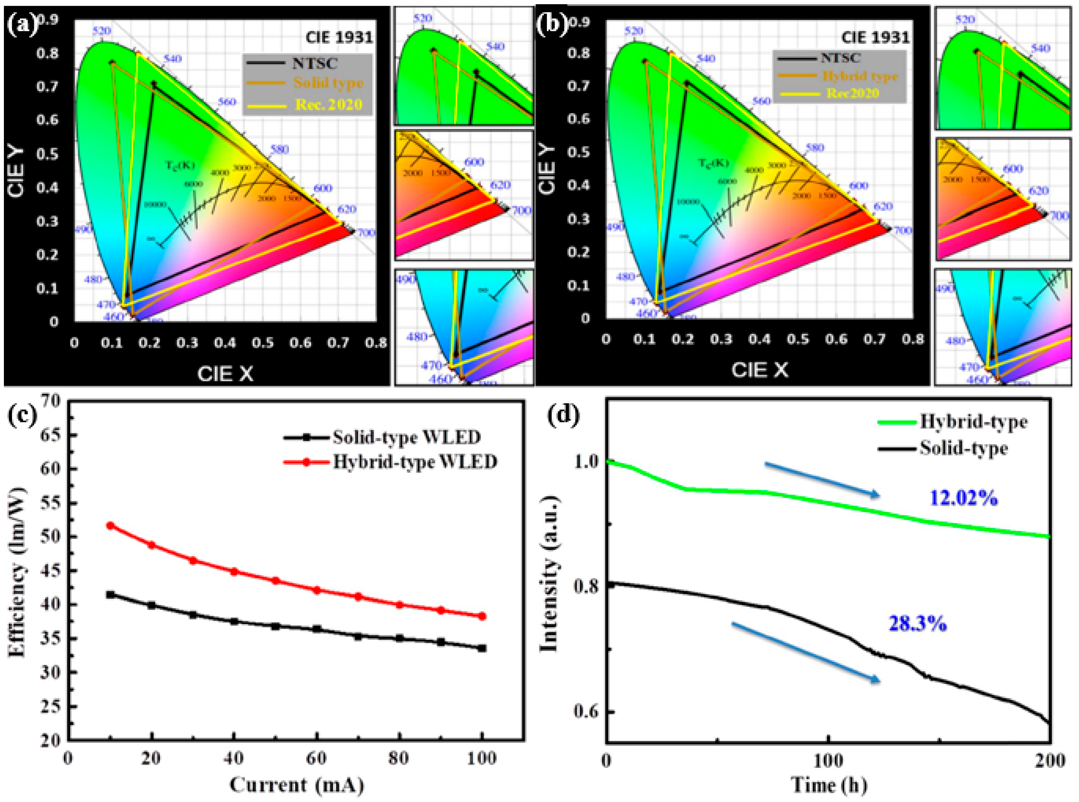
3.2. Perovskite QD-Based WLED
3.3. Flexible WLED
4. Conclusions
Author Contributions
Funding
Acknowledgments
Conflicts of Interest
References
- Ashoori, R.C. Electrons in artificial atoms. Nature 1996, 379, 413–419. [Google Scholar] [CrossRef]
- Banin, U.; Cao, Y.; Katz, D.; Millo, O. Identification of atomic-like electronic states in indium arsenide nanocrystal quantum dots. Nature 1999, 400, 542–544. [Google Scholar] [CrossRef]
- Kastner, M.A. The single electron transistor and artificial atoms. Ann. Der Phys. 2000, 9, 885–894. [Google Scholar] [CrossRef]
- Han, H.V.; Lin, C.C.; Tsai, Y.L.; Chen, H.C.; Chen, K.J.; Yeh, Y.L.; Lin, W.Y.; Kuo, H.C.; Yu, P. A highly efficient hybrid GaAs solar cell based on colloidal-quantum-dot-sensitization. Sci. Rep. 2014, 4, 5734. [Google Scholar] [CrossRef]
- Hsu, S.; Huang, Y.; Kao, Y.; Kuo, H.; Horng, R.; Lin, C. The Analysis of Dual-Junction tandem solar cells enhanced by surface dispensed quantum dots. IEEE Photonics J. 2018, 10, 1–11. [Google Scholar] [CrossRef]
- Pattantyus-Abraham, A.G.; Kramer, I.J.; Barkhouse, A.R.; Wang, X.; Konstantatos, G.; Debnath, R.; Levina, L.; Raabe, I.; Nazeeruddin, M.K.; Gratzel, M.; et al. Depleted-Heterojunction colloidal quantum dot solar cells. ACS Nano 2010, 4, 3374–3380. [Google Scholar] [CrossRef]
- Schaller, R.D.; Klimov, V.I. High Efficiency Carrier Multiplication in PbSe Nanocrystals: Implications for Solar Energy Conversion. Phys. Rev. Lett. 2004, 92, 186601. [Google Scholar] [CrossRef]
- Tsai, Y.L.; Lin, C.C.; Han, H.V.; Chang, C.K.; Chen, H.C.; Chen, K.J.; Lai, W.C.; Sheu, J.K.; Lai, F.I.; Yu, P.; et al. Improving efficiency of InGaN/GaN multiple quantum well solar cells using CdS quantum dots and distributed Bragg reflectors. Sol. Energy Mater. Sol. Cells 2013, 117, 531–536. [Google Scholar] [CrossRef]
- Konstantatos, G.; Sargent, E.H. Solution-Processed quantum dot photodetectors. Proc. IEEE 2009, 97, 1666–1683. [Google Scholar] [CrossRef]
- Pal, B.N.; Robel, I.; Mohite, A.; Laocharoensuk, R.; Werder, D.J.; Klimov, V.I. High-Sensitivity p–n Junction Photodiodes based on PbS nanocrystal quantum dots. Adv. Funct. Mater. 2012, 22, 1741–1748. [Google Scholar] [CrossRef]
- Koh, W.-K.; Saudari, S.R.; Fafarman, A.T.; Kagan, C.R.; Murray, C.B. Thiocyanate-Capped PbS nanocubes: Ambipolar transport enables quantum dot based circuits on a flexible substrate. Nano Lett. 2011, 11, 4764–4767. [Google Scholar] [CrossRef] [PubMed]
- Algar, W.R.; Krull, U.J. Quantum dots as donors in fluorescence resonance energy transfer for the bioanalysis of nucleic acids, proteins, and other biological molecules. Anal. Bioanal. Chem. 2008, 391, 1609–1618. [Google Scholar] [CrossRef] [PubMed]
- Dahan, M.; Lévi, S.; Luccardini, C.; Rostaing, P.; Riveau, B.; Triller, A. Diffusion Dynamics of Glycine receptors revealed by single-quantum dot tracking. Science 2003, 302, 442–445. [Google Scholar] [CrossRef]
- Marchuk, K.; Guo, Y.; Sun, W.; Vela, J.; Fang, N. High-Precision Tracking with Non-blinking Quantum Dots Resolves Nanoscale Vertical Displacement. J. Am. Chem. Soc. 2012, 134, 6108–6111. [Google Scholar] [CrossRef] [PubMed]
- Selvin, P. New Small Quantum Dots for Neuroscience (Presentation Video) (SPIE BiOS); SPIE: San Francisco, CA, USA, 2014. [Google Scholar]
- Chen, K.J.; Lin, C.C.; Han, H.V.; Lee, C.Y.; Chien, S.H.; Wang, K.Y.; Chiu, S.H.; Tu, Z.Y.; Li, J.R.; Chen, T.M.; et al. Wide-Range correlated color temperature light generation from resonant cavity hybrid quantum dot light-emitting diodes. IEEE J. Sel. Top. Quantum Electron. 2015, 21, 23–29. [Google Scholar] [CrossRef]
- Lin, H.Y.; Wang, S.W.; Lin, C.C.; Chen, K.J.; Han, H.V.; Tu, Z.Y.; Tu, H.H.; Chen, T.M.; Shih, M.H.; Lee, P.T.; et al. Excellent Color Quality of white light-emitting diodes by embedding quantum dots in polymers material. IEEE J. Sel. Top. Quantum Electron. 2015, 22, 35–41. [Google Scholar] [CrossRef]
- Liu, C.Y.; Chen, T.P.; Huang, J.K.; Lin, T.N.; Huang, C.Y.; Li, X.L.; Kuo, H.C.; Shen, J.L.; Chang, C.Y. Enhanced Color-Conversion Efficiency of hybrid nanostructured-cavities InGaN/GaN light-emitting diodes consisting of nontoxic InP quantum dots. IEEE J. Sel. Top. Quantum Electron. 2017, 23, 1–7. [Google Scholar] [CrossRef]
- Shirasaki, Y.; Supran, G.J.; Bawendi, M.G.; Bulović, V. Emergence of colloidal quantum-dot light-emitting technologies. Nat. Photonics 2013, 7, 13–23. [Google Scholar] [CrossRef]
- Smeeton, T.M.; Angioni, E.; Boardman, E.A.; Izumi, M.; Iwata, N.; Nakanishi, Y.; Ishida, T. 54-1: Invited Paper: Development of electroluminescent QD-LED displays. SID Symp. Dig. Tech. Pap. 2019, 50, 742–745. [Google Scholar] [CrossRef]
- Zhang, F.; Liu, J.; You, G.; Zhang, C.; Mohney, S.E.; Park, M.J.; Kwak, J.S.; Wang, Y.; Koleske, D.D.; Xu, J. Nonradiative energy transfer between colloidal quantum dot-phosphors and nanopillar nitride LEDs. Opt. Express 2012, 20 (Suppl. 2), A333–A339. [Google Scholar] [CrossRef]
- Leng, M.; Yang, Y.; Zeng, K.; Chen, Z.; Tan, Z.; Li, S.; Li, J.; Xu, B.; Li, D.; Hautzinger, M.P.; et al. All-Inorganic Bismuth-Based perovskite quantum dots with bright blue photoluminescence and excellent stability. Adv. Funct. Mater. 2018, 28, 1704446. [Google Scholar] [CrossRef]
- Li, X.; Wu, Y.L.; Zhang, S.; Cai, B.; Gu, Y.; Song, J.; Zeng, H. CsPbX3 Quantum Dots for lighting and displays: Room-Temperature synthesis, photoluminescence superiorities, underlying origins and white light-emitting diodes. Adv. Funct. Mater. 2016, 26, 2435–2445. [Google Scholar] [CrossRef]
- Nedelcu, G.; Protesescu, L.; Yakunin, S.; Bodnarchuk, M.I.; Grotevent, M.J.; Kovalenko, M.V. Fast Anion-Exchange in Highly Luminescent Nanocrystals of Cesium Lead Halide Perovskites (CsPbX3, X = Cl, Br, I). Nano Lett. 2015, 15, 5635–5640. [Google Scholar] [CrossRef] [PubMed]
- Sun, C.; Zhang, Y.; Ruan, C.; Yin, C.; Wang, X.; Wang, Y.; Yu, W.W. Efficient and Stable White LEDs with Silica-Coated inorganic perovskite quantum dots. Adv. Mater. 2016, 28, 10088–10094. [Google Scholar] [CrossRef]
- Swarnkar, A.; Chulliyil, R.; Ravi, V.K.; Irfanullah, M.; Chowdhury, A.; Nag, A. Colloidal CsPbBr3 Perovskite Nanocrystals: Luminescence beyond Traditional Quantum Dots (in eng). Angew. Chem. (Int. Ed. Engl.) 2015, 54, 15424–15428. [Google Scholar] [CrossRef] [PubMed]
- Sinatra, L.; Lutfullin, M.; Mozo, S.L.; Pan, J.; Bakr, O.M. P-124: Perovskite Quantum Dots Display: Challenges and Opportunities. SID Symp. Dig. Tech. Pap. 2019, 50, 1712–1715. [Google Scholar] [CrossRef]
- Sinatra, L.; Lutfullin, M.; Abbas, A.S.; Pan, J.; Bakr, O.M. P-203: Late-News Poster: Novel Techniques for highly stable luminescent perovskite halide quantum dots. SID Symp. Dig. Tech. Pap. 2018, 49, 1681–1684. [Google Scholar] [CrossRef]
- Azpiroz, J.M.; Mosconi, E.; Bisquert, J.; de Angelis, F. Defect migration in methylammonium lead iodide and its role in perovskite solar cell operation. Energy Environ. Sci. 2015, 8, 2118–2127. [Google Scholar] [CrossRef]
- Koscher, B.A.; Swabeck, J.K.; Bronstein, N.D.; Alivisatos, A.P. Essentially Trap-Free CsPbBr3 Colloidal Nanocrystals by Postsynthetic Thiocyanate Surface Treatment. J. Am. Chem. Soc. 2017, 139, 6566–6569. [Google Scholar] [CrossRef]
- Wu, Y.; Li, X.; Zeng, H. Highly Luminescent and stable halide perovskite nanocrystals. ACS Energy Lett. 2019, 4, 673–681. [Google Scholar] [CrossRef]
- Wei, Y.; Cheng, Z.; Lin, J. An overview on enhancing the stability of lead halide perovskite quantum dots and their applications in phosphor-converted LEDs. Chem. Soc. Rev. 2019, 48, 310–350. [Google Scholar] [CrossRef] [PubMed]
- Lv, W.; Li, L.; Xu, M.; Hong, J.; Tang, X.; Xu, L.; Wu, Y.; Zhu, R.; Chen, R.; Huang, W. Improving the Stability of metal halide perovskite quantum dots by encapsulation. Adv. Mater. 2019, 31, 1900682. [Google Scholar] [CrossRef] [PubMed]
- Ahn, H.; Hong, S.; Kwon, O. An Active matrix micro-pixelated LED display driver for high luminance uniformity using resistance mismatch compensation method. IEEE Trans. Circuits Syst. II Express Briefs 2018, 65, 724–728. [Google Scholar] [CrossRef]
- Chen, C.; Chen, H.; Liao, J.; Yu, C.; Wu, M. Fabrication and Characterization of Active-Matrix 960 × 540 Blue GaN-Based Micro-LED Display. IEEE J. Quantum Electron. 2019, 55, 1–6. [Google Scholar] [CrossRef]
- Jiang, H.X.; Lin, J.Y. Nitride micro-LEDs and beyond—A decade progress review. Opt. Express 2013, 21, A475–A484. [Google Scholar] [CrossRef] [PubMed]
- Corbett, B.; Loi, R.; Zhou, W.; Liu, D.; Ma, Z. Transfer print techniques for heterogeneous integration of photonic components. Prog. Quantum Electron. 2017, 52, 1–17. [Google Scholar] [CrossRef]
- Chen, K.J.; Han, H.V.; Lin, B.; Chen, H.; Shih, M.; Chien, S.; Wang, K.Y.; Tsai, H.H.; Yu, P.; Lee, P.; et al. Improving the angular color uniformity of hybrid phosphor structures in white light-emitting diodes. IEEE Electron Device Lett. 2013, 34, 1280–1282. [Google Scholar] [CrossRef]
- Kim, J.S.; Jeon, P.E.; Park, Y.H.; Choi, J.C.; Park, H.L.; Kim, G.C.; Kim, T.W. DEPARTMENT OF ELECTRONIC ENGINEERING. White-light generation through ultraviolet-emitting diode and white-emitting phosphor. Appl. Phys. Lett. 2004, 85, 3696–3698. [Google Scholar] [CrossRef]
- Narendran, N.; Gu, Y.; Freyssinier, J.P.; Yu, H.; Deng, L. Solid-state lighting: Failure analysis of white LEDs. J. Cryst. Growth 2004, 268, 449–456. [Google Scholar] [CrossRef]
- Lee, J.; Sundar, V.C.; Heine, J.R.; Bawendi, M.G.; Jensen, K.F. Full Color Emission from II–VI Semiconductor Quantum Dot–Polymer Composites. Adv. Mater. 2000, 12, 1102–1105. [Google Scholar] [CrossRef]
- Chen, K.; Chen, H.; Tsai, K.; Lin, C.; Tsai, H.; Chien, S.; Cheng, B.; Hsu, Y.; Shih, M.; Tsai, C.; et al. Resonant-Enhanced full-color emission of quantum-dot-based display technology using a pulsed spray method. Adv. Funct. Mater. 2012, 22, 5138–5143. [Google Scholar] [CrossRef]
- Abe, S.; Joos, J.J.; Martin, L.I.D.J.; Hens, Z.; Smet, P.F. Hybrid remote quantum dot/powder phosphor designs for display backlights. Light Sci. Appl. 2017, 6, e16271. [Google Scholar] [CrossRef] [PubMed]
- Lin, H.Y.; Sher, C.W.; Hsieh, D.H.; Chen, X.Y.; Chen, H.M.; Chen, T.M.; Lau, K.M.; Chen, C.H.; Lin, C.C.; Kuo, H.C. Optical cross-talk reduction in a quantum-dot-based full-color micro-light-emitting-diode display by a lithographic-fabricated photoresist mold. Photonics Res. 2017, 5, 411–416. [Google Scholar] [CrossRef]
- Han, H.V.; Lin, H.Y.; Lin, C.C.; Chong, W.C.; Li, J.R.; Chen, K.J.; Yu, P.; Chen, T.M.; Chen, H.M.; Lau, K.M.; et al. Resonant-enhanced full-color emission of quantum-dot-based micro LED display technology. Opt. Express 2015, 23, 32504–32515. [Google Scholar] [CrossRef] [PubMed]
- Chen, S.W.; Shen, C.C.; Wu, T.; Liao, Z.Y.; Chen, L.F.; Zhou, J.R.; Lee, C.F.; Lin, C.H.; Lin, C.C.; Sher, C.W.; et al. Full-color monolithic hybrid quantum dot nanoring micro light-emitting diodes with improved efficiency using atomic layer deposition and nonradiative resonant energy transfer. Photonics Res. 2019, 7, 416–422. [Google Scholar] [CrossRef]
- Hu, Z.; Yin, Y.; Ali, M.U.; Peng, W.; Zhang, S.; Li, D.; Zou, T.; Li, Y.; Jiao, S.; Chen, S.J.; et al. Inkjet printed uniform quantum dots as color conversion layers for full-color OLED displays. Nanoscale 2020, 12, 2103–2110. [Google Scholar] [CrossRef] [PubMed]
- Yue, S. P-12.4: Quantum dot photoresist for Color Filter application. SID Symp. Digest Tech. Pap. 2018, 49, 724–726. [Google Scholar] [CrossRef]
- Chen, S.W.; Huang, Y.M.; Singh, K.J.; Hsu, Y.C.; Liou, F.J.; Song, J.; Choi, J.; Lee, P.T.; Lin, C.C.; Chen, Z.; et al. Full-color micro-LED display with high color stability using semipolar (20–21) InGaN LEDs and quantum-dot photoresist. Photonics Res. 2020, 8, 630–636. [Google Scholar] [CrossRef]
- Chen, G.; Wei, B.; Lee, C.; Lee, H. Monolithic Red/Green/Blue Micro-LEDs with HBR and DBR structures. IEEE Photonics Technol. Lett. 2018, 30, 262–265. [Google Scholar] [CrossRef]
- Gou, F.; Hsiang, E.-L.; Tan, G.; Lan, Y.-F.; Tsai, C.-Y.; Wu, S.-T. Tripling the optical efficiency of Color-converted Micro-LED displays with Funnel-Tube array. Crystals 2019, 9, 39. [Google Scholar] [CrossRef]
- Bower, C.A.; Meitl, M.A.; Raymond, B.; Radauscher, E.; Cok, R.; Bonafede, S.; Gomez, D.; Moore, T.; Prevatte, C.; Fisher, B.; et al. Emissive displays with transfer-printed assemblies of 8 μm × 15 μm inorganic light-emitting diodes. Photonics Res. 2017, 5, A23–A29. [Google Scholar] [CrossRef]
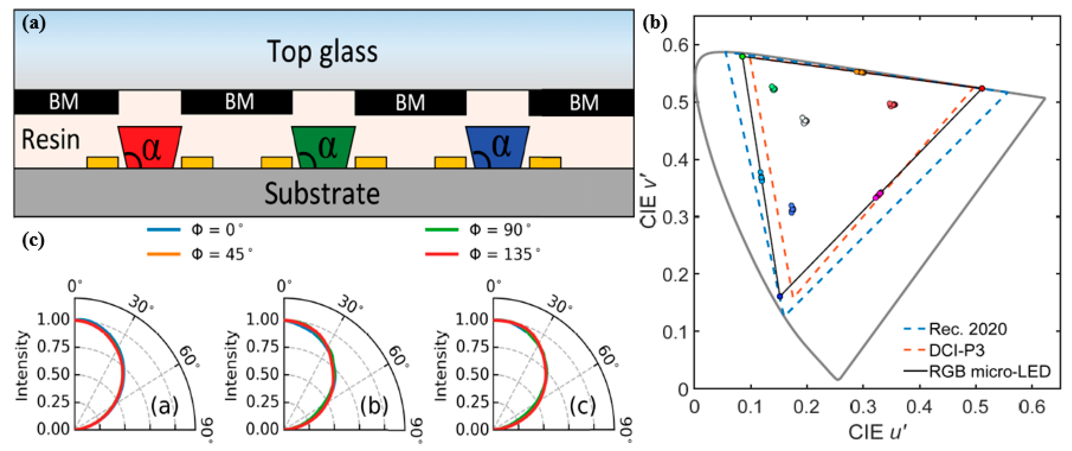
- Gou, F.; Hsiang, E.L.; Tan, G.; Chou, P.T.; Li, Y.L.; Lan, Y.F.; Wu, S.T. Angular color shift of micro-LED displays. Opt. Express 2019, 27, A746–A757. [Google Scholar] [CrossRef] [PubMed]
- Jang, E.; Jun, S.; Jang, H.; Lim, J.; Kim, B.; Kim, Y. White-light-emitting diodes with quantum dot color converters for display backlights, (in eng). Adv. Mater. (Deerfield Beach Fla.) 2010, 22, 3076–3080. [Google Scholar] [CrossRef] [PubMed]
- Nizamoglu, S.; Demir, H.V. Hybrid white light sources based on layer-by-layer assembly of nanocrystals on near-UV emitting diodes. Nanotechnology 2007, 18, 405702. [Google Scholar] [CrossRef]
- Ziegler, J.; Xu, S.; Kucur, E.; Meister, F.; Batentschuk, M.; Gindele, F.; Nann, T. Silica-Coated InP/ZnS Nanocrystals as converter material in white LEDs. Adv. Mater. 2008, 20, 4068–4073. [Google Scholar] [CrossRef]
- Dai, X.; Deng, Y.; Peng, X.; Jin, Y. Quantum-Dot light-emitting diodes for large-area displays: Towards the dawn of commercialization. Adv. Mater. 2017, 29, 1607022. [Google Scholar] [CrossRef]
- Fang, F.; Chen, W.; Li, Y.; Liu, H.; Mei, M.; Zhang, R.; Hao, J.; Mikita, M.; Cao, W.; Pan, R.; et al. Employing polar solvent controlled ionization in precursors for synthesis of high-quality inorganic perovskite nanocrystals at room temperature. Adv. Funct. Mater. 2018, 28, 1706000. [Google Scholar] [CrossRef]
- Wang, P.; Bai, X.; Sun, C.; Zhang, X.; Zhang, T.; Zhang, Y. Multicolor fluorescent light-emitting diodes based on cesium lead halide perovskite quantum dots. Appl. Phys. Lett. 2016, 109, 063106. [Google Scholar] [CrossRef]
- Chen, H.; He, J.; Wu, S. Recent Advances on quantum-dot-enhanced liquid-crystal displays. IEEE J. Sel. Top. Quantum Electron. 2017, 23, 1–11. [Google Scholar] [CrossRef]
- Li, Z.T.; Song, C.J.; Qiu, Z.Y.; Li, J.S.; Cao, K.; Ding, X.R.; Tang, Y. Study on the thermal and optical performance of quantum dot white light-emitting diodes using metal-based inverted packaging structure. IEEE Trans. Electron Devices 2019, 66, 3020–3027. [Google Scholar] [CrossRef]
- Wang, H.; Mou, Y.; Peng, Y.; Liu, J.; Liang, R.; Chen, M.; Dai, J.; Chen, C. White Light-Emitting diodes with high color quality fabricated using phosphor-in-glass integrated with liquid-type quantum dot. IEEE Electron Device Lett. 2019, 40, 601–604. [Google Scholar] [CrossRef]
- Xie, B.; Chen, W.; Hao, J.; Wu, D.; Yu, X.; Chen, Y.; Hu, R.; Wang, K.; Luo, X. Structural optimization for remote white light-emitting diodes with quantum dots and phosphor: Packaging sequence matters. Opt. Express 2016, 24, A1560–A1570. [Google Scholar] [CrossRef] [PubMed]
- Xie, B.; Cheng, Y.; Hao, J.; Yu, X.; Shu, W.; Wang, K.; Luo, X. White light-emitting diodes with enhanced Efficiency and thermal stability optimized by quantum dots-silica nanoparticles. IEEE Trans. Electron Devices 2018, 65, 605–609. [Google Scholar] [CrossRef]
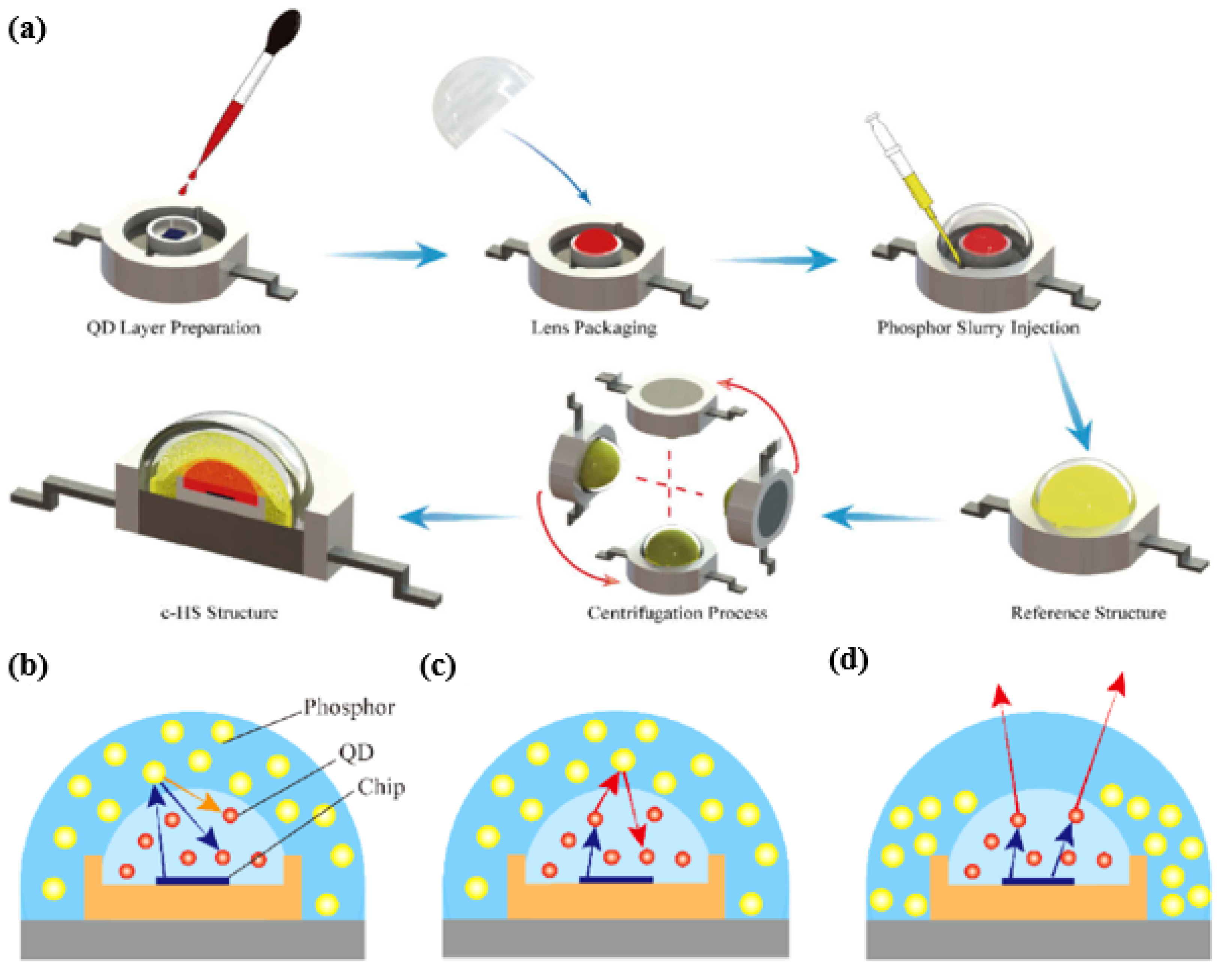
- Li, Z.; Zheng, J.; Li, J.; Zhan, W.; Tang, Y. Efficiency enhancement of quantum dot-phosphor hybrid white-light-emitting diodes using a centrifugation-based quasi-horizontal separation structure. Opt. Express 2020, 28, 13279–13289. [Google Scholar] [CrossRef]
- Wang, H.; Li, J.; Zhao, X.; Ding, X.; Tang, Y.; Li, Z.; Yu, B. Study on Optical Consistency of Centrifuged LEDs in packaging processes. IEEE Trans. Compon. Packag. Manuf. Technol. 2019, 9, 1376–1387. [Google Scholar] [CrossRef]
- Yan, C.; Wang, H.; Cao, K.; Fan, D.; Li, J.-S.; Tang, Y.; Ding, X. Research on centrifugal sedimentation for improving luminous flux of the quantum-dots LED devices. In Proceedings of the 2018 19th International Conference on Electronic Packaging Technology (ICEPT), Shanghai, China, 8–11 August 2018; Volume 8, pp. 1437–1441. [Google Scholar]
- Cho, J.; Schubert, E.F.; Kim, J.K. Efficiency droop in light-emitting diodes: Challenges and countermeasures. Laser Photonics Rev. 2013, 7, 408–421. [Google Scholar] [CrossRef]
- Verzellesi, G.; Saguatti, D.; Meneghini, M.; Bertazzi, F.; Goano, M.; Meneghesso, G.; Zanoni, E. Efficiency droop in InGaN/GaN blue light-emitting diodes: Physical mechanisms and remedies. J. Appl. Phys. 2013, 114, 071101. [Google Scholar] [CrossRef]
- Langer, R.; Simon, J.; Ortiz, V.; Pelekanos, N.; Barski, A.; André, R.; Godlewski, M. Giant electric fields in unstrained GaN single quantum wells. Appl. Phys. Lett. 1999, 74, 3827–3829. [Google Scholar] [CrossRef]
- Iveland, J.; Martinelli, L.; Peretti, J.; Speck, J.S.; Weisbuch, C. Direct measurement of auger electrons emitted from a semiconductor light-emitting diode under electrical injection: Identification of the dominant mechanism for efficiency droop. Phys. Rev. Lett. 2013, 110, 177406. [Google Scholar] [CrossRef]
- Kim, M.H.; Schubert, M.F.; Dai, Q.; Kim, J.K.; Schubert, E.F.; Piprek, J.; Park, Y. Origin of efficiency droop in GaN-based light-emitting diodes. Appl. Phys. Lett. 2007, 91, 183507. [Google Scholar] [CrossRef]
- Zhao, C.; Tang, C.W.; Lai, B.; Cheng, G.; Wang, J.; Lau, K.M. Low-efficiency-droop InGaN quantum dot light-emitting diodes operating in the “green gap”. Photonics Res. 2020, 8, 750–754. [Google Scholar] [CrossRef]
- Lin, C.-H.; Verma, A.; Kang, C.-Y.; Pai, Y.-M.; Chen, T.-Y.; Yang, J.-J.; Sher, C.-W.; Yang, Y.-Z.; Lee, P.-T.; Lin, C.-C.; et al. Hybrid-type white LEDs based on inorganic halide perovskite QDs: Candidates for wide color gamut display backlights. Photonics Res. 2019, 7, 579–585. [Google Scholar] [CrossRef]
- Xie, B.; Hu, R.; Yu, X.; Shang, B.; Ma, Y.; Luo, X. Effect of Packaging Method on performance of light-emitting diodes with quantum dot phosphor. IEEE Photonics Technol. Lett. 2016, 28, 1115–1118. [Google Scholar] [CrossRef]
- Yuan, Y.; Zhang, J.; Liang, G.; Yang, X. Rapid fluorescent detection of neurogenin3 by CdTe quantum dot aggregation. Analyst 2012, 137, 1775–1778. [Google Scholar] [CrossRef]
- Cho, K.-S.; Lee, E.K.; Joo, W.-J.; Jang, E.; Kim, T.-H.; Lee, S.J.; Kwon, S.-J.; Han, J.Y.; Kim, B.-K.; Choi, B.L.; et al. High-performance crosslinked colloidal quantum-dot light-emitting diodes. Nat. Photonics 2009, 3, 341–345. [Google Scholar] [CrossRef]
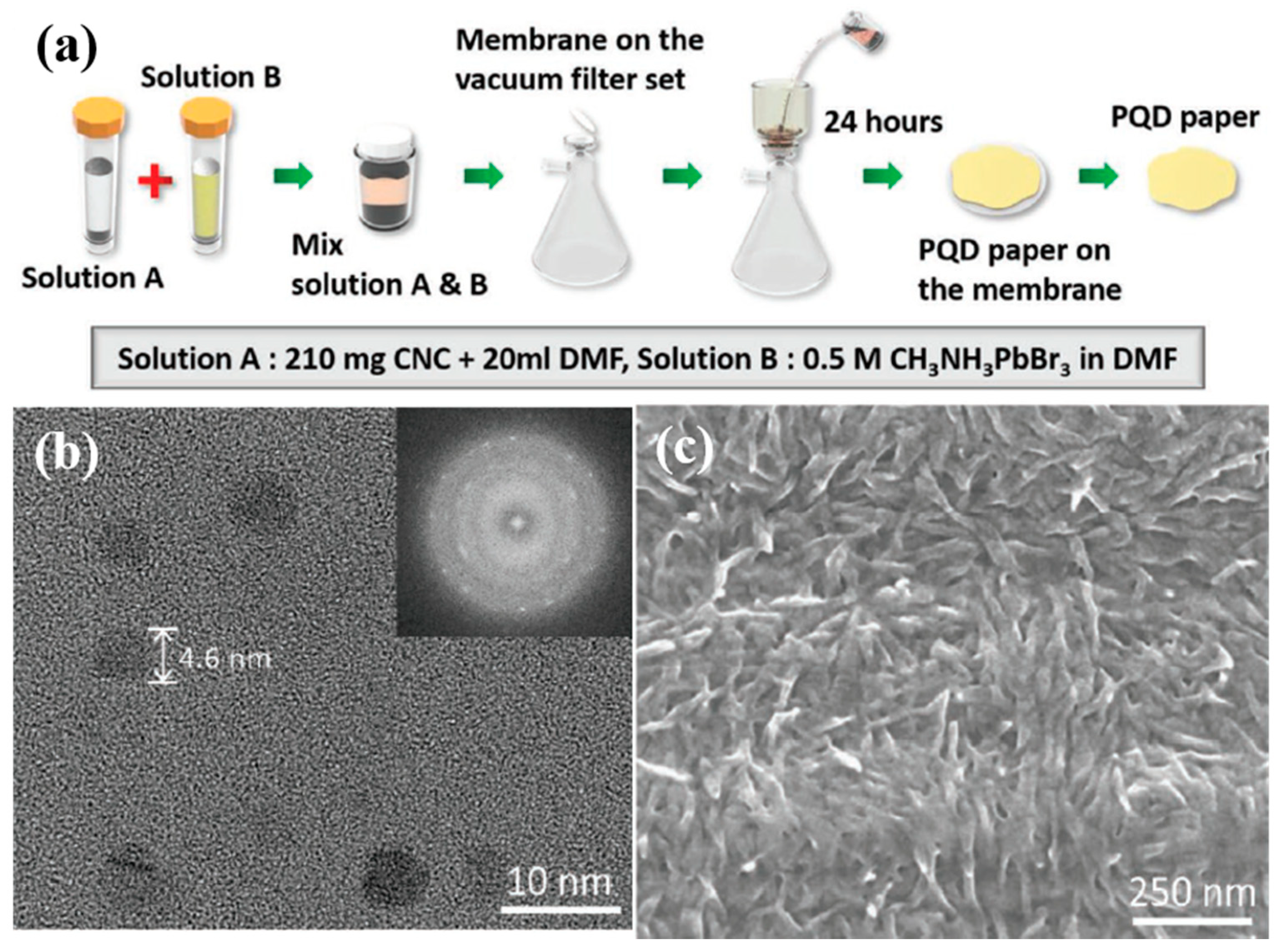
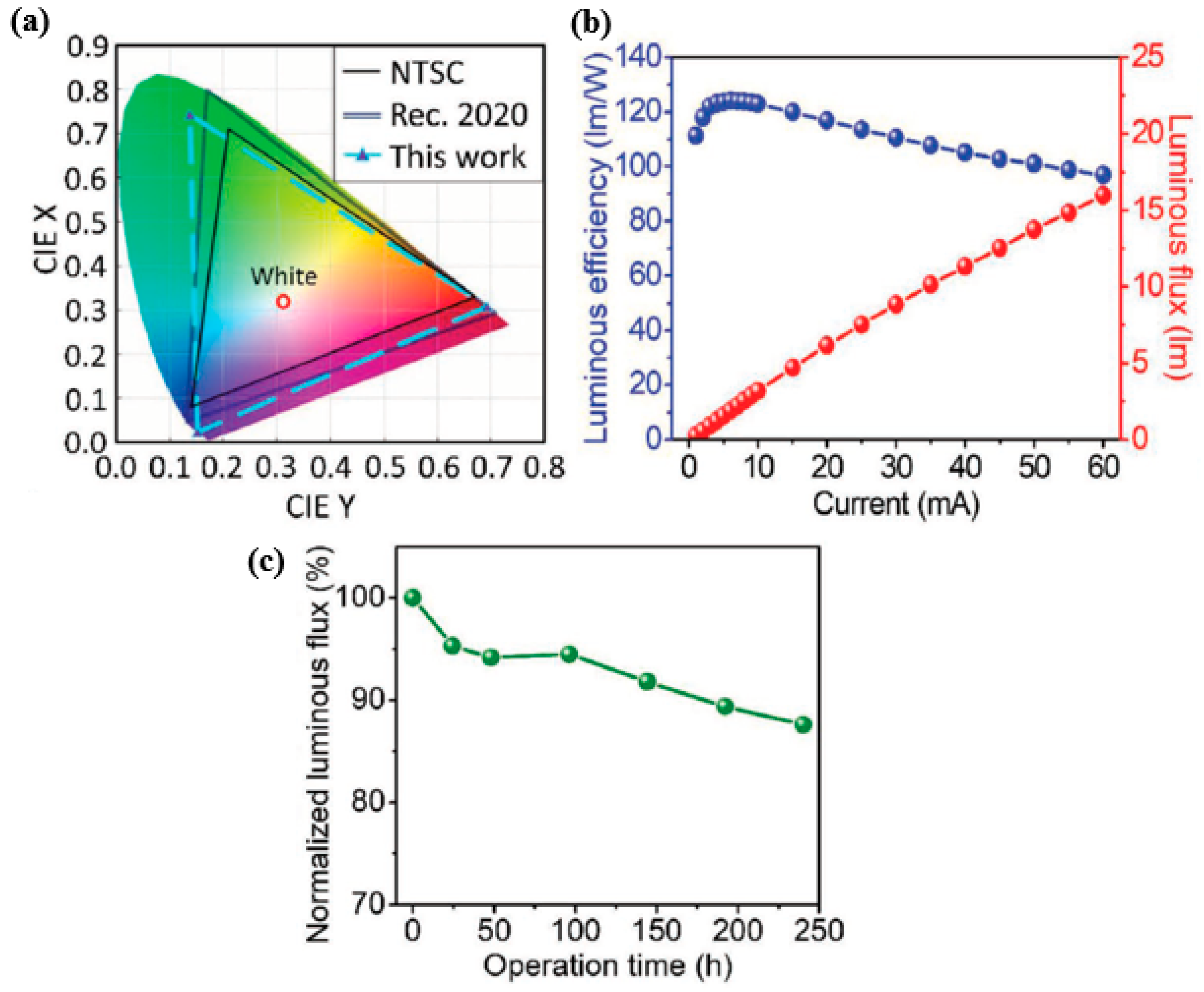
- Kang, C.; Lin, C.; Lin, C.; Li, T.; Chen, S.H.; Tsai, C.; Sher, C.; Wu, T.; Lee, P.; Xu, X.; et al. Highly efficient and stable white light-emitting diodes using perovskite quantum dot paper. Adv. Sci. (Weinh. Baden-Wurtt. Ger.) 2019, 6, 1902230. [Google Scholar] [CrossRef]
- Wang, H.C.; Lin, S.Y.; Tang, A.C.; Singh, B.P.; Tong, H.C.; Chen, C.Y.; Lee, Y.C.; Tsai, T.L.; Liu, R.S. Mesoporous silica particles integrated with all-inorganic CsPbBr3 Perovskite quantum-dot nanocomposites (MP-PQDs) with high stability and wide color gamut used for backlight display. Angew. Chemie Int. Ed. 2016, 55, 7924–7929. [Google Scholar] [CrossRef] [PubMed]
- De Roo, J.; Ibáñez, M.; Geiregat, P.; Nedelcu, G.; Walravens, W.; Maes, J.; Martins, J.C.; Van Driessche, I.; Kovalenko, M.V.; Hens, Z. Highly Dynamic Ligand Binding and Light Absorption Coefficient of Cesium Lead Bromide Perovskite Nanocrystals. ACS Nano 2016, 10, 2071–2081. [Google Scholar] [CrossRef] [PubMed]
- Akkerman, Q.A.; D’Innocenzo, V.; Accornero, S.; Scarpellini, A.; Petrozza, A.; Prato, M.; Manna, L. Tuning the Optical Properties of Cesium Lead Halide Perovskite Nanocrystals by Anion Exchange Reactions. J. Am. Chem. Soc. 2015, 137, 10276–10281. [Google Scholar] [CrossRef]
- Xie, Y.; Yu, Y.; Gong, J.; Yang, C.; Zeng, P.; Dong, Y.; Yang, B.; Liang, R.; Ou, Q.; Zhang, S. Encapsulated room-temperature synthesized CsPbX3 perovskite quantum dots with high stability and wide color gamut for display. Opt. Mater. Express 2018, 8, 3494–3505. [Google Scholar] [CrossRef]
- Kim, R.-H.; Kim, S.; Song, Y.M.; Jeong, H.; Kim, T.; Lee, J.; Li, X.; Choquette, K.D.; Rogers, J.A. Flexible vertical light emitting diodes. Small 2012, 8, 3123–3128. [Google Scholar] [CrossRef]
- Huang, P.-H.; Huang, T.-C.; Sun, Y.-T.; Yang, S.-Y. Large-area and thin light guide plates fabricated using UV-based imprinting. Opt. Express 2008, 16, 15033–15038. [Google Scholar] [CrossRef]
- Sher, C.-W.; Chen, K.-J.; Lin, C.-C.; Han, H.-V.; Lin, H.-Y.; Tu, Z.-Y.; Tu, H.-H.; Honjo, K.; Jiang, H.-Y.; Ou, S.-L.; et al. Large-area, uniform white light LED source on a flexible substrate. Opt. Express 2015, 23, A1167–A1178. [Google Scholar] [CrossRef]


| Methods | Description | |
|---|---|---|
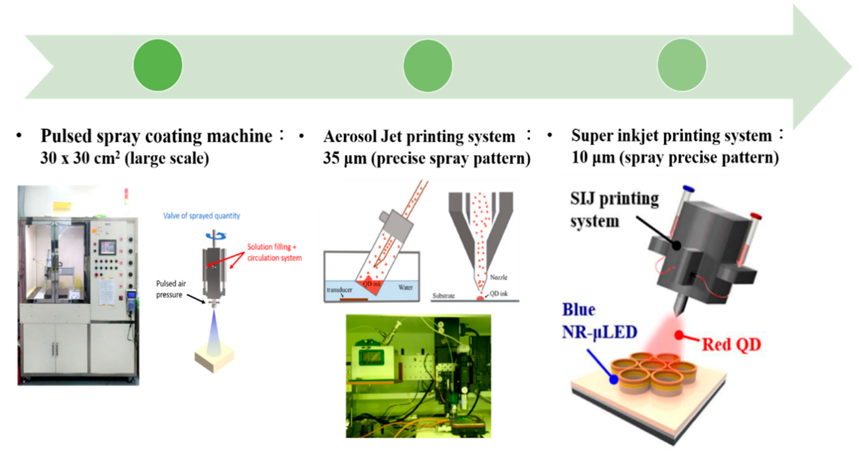
| Pulsed-Spray Coating Machine |  | The operation is precisely controlled by a computer and its quality of spray was quite stable each time. The disadvantage is the spray diameters which is large, which could not be used to spray precise pattern. |
| Aerosol Jet Printing System |  | The QDs solution was aerosolized by the ultrasonic vibration. The Aerosol Jet process began with a mist generator that atomized liquid materials into small droplets. The disadvantage is the large spray area, and QDs also printed out of the windows. |
| Super-Inkjet Printing System [46] |  | The pressure generated by the oscillating electric field is used by this printing machine to print the QDs. With better control of QDs-inks, it provides fine-linewidth pattern. In addition, printing sufficiently dense QDs caused the higher color conversion of the color Red and Green is time consuming. |
| Quantum Dots Photoresist methods |  | Quantum dots photoresist methods by photolithography is a fast and convenience method. This method can control the thickness of QDPR to prevent the leakage blue light. However, the disadvantage is QD usage is high. |
| Types | Performance | Challenges |
|---|---|---|
| QDs-based displays (CdSe) | Improved color and energy efficiency, good at absorption high energy blue light and re-emitting at longer wavelength. CdSe-based QDs has more than 90% PLQY and less than 30 nm FWHM leading to better color quality. | Reduction in EQE of the devices, subjected to non- recombination processes including surface trapping, Auger recombination, etc. Toxicity of Cd-based QDs limits their use. |
| PQDs-based displays | Impressive ultra-narrow linewidth of 15–18 nm for green, tunable wavelengths leading to higher efficiency and brightness. Emission of light strongly and efficiently in a variety of colors. | Stability issues making them susceptible to degradation from high temperature and light flux. Color shift problem. Content of lead in PQDs. |
| QDs-based Flexible displays | Growing demand for flexible and wearable displays, integration of flexible QLEDs with wearable sensors, micro-controllers, wireless communication units for next generation consumer electronics. | Some of the issues include thinness and robustness of the display, reliability, high cost, poor optical clarity, issue of mass production |
© 2020 by the authors. Licensee MDPI, Basel, Switzerland. This article is an open access article distributed under the terms and conditions of the Creative Commons Attribution (CC BY) license (http://creativecommons.org/licenses/by/4.0/).
Share and Cite
Huang, Y.-M.; Singh, K.J.; Liu, A.-C.; Lin, C.-C.; Chen, Z.; Wang, K.; Lin, Y.; Liu, Z.; Wu, T.; Kuo, H.-C. Advances in Quantum-Dot-Based Displays. Nanomaterials 2020, 10, 1327. https://doi.org/10.3390/nano10071327
Huang Y-M, Singh KJ, Liu A-C, Lin C-C, Chen Z, Wang K, Lin Y, Liu Z, Wu T, Kuo H-C. Advances in Quantum-Dot-Based Displays. Nanomaterials. 2020; 10(7):1327. https://doi.org/10.3390/nano10071327
Chicago/Turabian StyleHuang, Yu-Ming, Konthoujam James Singh, An-Chen Liu, Chien-Chung Lin, Zhong Chen, Kai Wang, Yue Lin, Zhaojun Liu, Tingzhu Wu, and Hao-Chung Kuo. 2020. "Advances in Quantum-Dot-Based Displays" Nanomaterials 10, no. 7: 1327. https://doi.org/10.3390/nano10071327
APA StyleHuang, Y.-M., Singh, K. J., Liu, A.-C., Lin, C.-C., Chen, Z., Wang, K., Lin, Y., Liu, Z., Wu, T., & Kuo, H.-C. (2020). Advances in Quantum-Dot-Based Displays. Nanomaterials, 10(7), 1327. https://doi.org/10.3390/nano10071327