Abstract
Gas coolers are critical elements of turbogenerator cooling systems, which ensure the reliability and stability of the thermal mode of high-power electric machines. The aim of this research is to improve the accuracy of thermal calculations of gas coolers by combining analytical methods with numerical CFD-modeling (Computation Fluid Dynamics). The cooler’s total cooling capacity is approximately 3.8 MW, distributed across three identical sections.An analytical calculation of heat transfer for a hydrogen-water gas cooler with finned tubes was performed, using classical dependencies to determine the heat transfer coefficients and pressure losses. The results were verified using three-dimensional CFD-modeling of the hydrogen flow through the cooler using the standard k-ε (k-epsilon) turbulence model. The discrepancy between the results of analytical and numerical calculations is less than 10%. The temperature of the cooled hydrogen at the outlet meets the design requirements (+40 °C); however, areas of uneven temperature distribution were identified that require further design optimization. The study introduces, for the first time, a combined approach using analytical calculations and CFD by thoroughly evaluating the heat exchange between the cooling tube fins and hydrogen. This scientific solution enabled the simulation of hydrogen flow within the multi-stage cooler system. The proposed method has proven to be reliable and can be applied both at the design stage and for the analysis of upgraded cooling systems of turbogenerators.
1. Introduction
Gas coolers are critical components in the design of modern turbogenerators and Hydrogenerators and ensure the maintenance of a stable thermal operating mode necessary for the safe and efficient operation of powerful electric machines [,]. To ensure the specified thermal mode of modern generators, gas cooler designs are selected taking into account the unit power, requirements for dimensions, operating conditions and type of working environment. Given the constant increase in requirements for the productivity of power plants, the development and improvement of methods for calculating the correct heat-exchange areas and cooling gas flow parameters, as well as the development of effective monitoring algorithms is an important and urgent task of modern energy [].
Cooling systems of turbogenerators are classified according to the cooling medium used as follows: air, hydrogen–air, hydrogen–water, and for the most powerful units, combined schemes are used. The choice of scheme determines both thermal efficiency and requirements for reliability and safety. In terms of gas flow organization, the most progressive for modern generators are combined axial–radial ventilation schemes.
The efficiency of cooling generators is determined by the characteristics of heat-exchange between the cooling medium and the heat removal surfaces, which necessitates a thorough analysis of thermal hydraulic processes. In this regard, numerous analytical and numerical calculation methods are actively developed and applied, which provide sufficient accuracy for the design and operation of gas coolers.
The most common are still the classical methods of calculating gas coolers, based on traditional approaches, such as the NTU (Number of Transfer Units) and LMTD (logarithmic mean temperature difference) methods. Such approaches are based on the calculation formulas for heat transfer in pipes:
where —amount of heat [W]; —heat transfer coefficient [W/(m2·°C)]; F—heat-exchange surface area [m2]; —logarithmic mean temperature difference [°C].
In order to calculate the heat transfer coefficients, empirical correlations of Nusselt, Stanton, and Prandtl are used [,]. These methods allow for determining the required heat transfer surface and key parameters of heat-exchangers, in particular for smooth and finned tubes. Palanichamy C. and Nagaraj M. proposed an improved method for determining the Nusselt number for internally finned tubes, which allowed to increase the accuracy of analytical calculations by 10–15% []. The main advantage of these methods is still ease of use and sufficient accuracy for most engineering problems. They allow quick calculation of the required surface area, but they are significantly dependent on empirical correlations. This limits their application for new or optimized designs of gas coolers, and this method also makes it impossible to take into account the complex local pattern of temperatures and speeds.
In connection with the growing need for an accurate description of thermal and fluid dynamics in complex geometries, numerical methods, particularly those based on computational fluid dynamics, have gained considerable popularity. These methods allow for a detailed picture of heat transfer and flow processes in complex geometric configurations, in particular by solving the Reynolds-averaged Navier–Stokes (RANS) Equation in tensor form:
where —average speed of the flow; —speed fluctuations due to turbulence; μ—molecular viscosity; and —Reynolds stress term.
The Reynolds averaging process introduces an additional stress term, the Reynolds stress, into the equation. In solving the RANS equation, the Reynolds stress is expressed in terms of the average flow quantities.
The solution for the Reynolds stress term is given by the eddy viscosity hypothesis (Boussinesq hypothesis) in the form:
where μt—turbulent (eddy viscosity); —Kronecker delta.
The given equation is a combined one for the shear and normal components of Reynolds stress, where it can be concluded that the solution of the RANS equation depends on the solution of the equation for turbulent viscosity.
The main turbulence models used in such calculations are the k-ε turbulence models for modeling the average flow characteristics under turbulent flow conditions. In addition to the conservation equations, it additionally solves the term transfer equations. The two transferred variables are the turbulent kinetic energy (k), which determines the energy in the turbulence, and the turbulent dissipation rate (ε), which determines the rate of dissipation of the turbulent kinetic energy.
There are different variations in k-ε model, such as the following:
- Standard k-ε model—most common due to its simplicity and stability for free-shear flows, excellent for high Reynolds number applications, but has limitations in complex flows with significant gradients, vortices, or separation flows [];
- RNG k-ε model—this model modifies the dissipation rate equation, which improves calculations for swirling flows and turbulent zones [];
- Realizable k-ε model—developed to overcome the disadvantages of the standard model, provides increased accuracy for large pressure gradients and complex geometric shapes; however, this model gives unphysical values of turbulent viscosity in simulations that include stationary and turbulent zones [].
The model SST k-ω has recently received particular attention due to the ability to accurately describe complex flows with the presence of separations and speed gradients, which is typical of gas coolers. Adanta D. et al. established the advantage of this model over k-ε models, especially in the boundary layers of the flow; however, the standard k-ε model provides comparable accuracy for the specific flow conditions encountered in this study [].
An important direction of development of research methods was the optimization of design parameters of gas coolers using modern computational methods. As shown in the work of Mekki, B.S. [], the use of numerical simulation (CFD) and response surface method (RSM) allows for significantly reducing design costs and increasing heat transfer efficiency. These methods made it possible to optimize the geometry of the fins (fin pitch, tube diameter, location and configuration) and achieve an increase in the heat transfer coefficient by 5.4–12.2%.
NSGA II is often used for multi-criteria optimization. Li et al.’s research combined CFD with NSGA II to optimize plate heat exchangers: the angle of the toothed fin, oil and water flow rates were varied, and the objective functions were heat transfer capacity, pressure drop and outlet temperature []. It is also worth noting that NSGA-II is successfully applied to other configurations as well: for example, in shell-and-tube heat exchangers. It allows for determining the compromise between the j-factor (heat transfer coefficient) and the f-factor (hydraulic losses). For example, the result was an increase in the j-factor by 3–4% while reducing the f-factor by 7–9% [].
Although CFD+GA is implemented less frequently in the turbogenerator industry, there are already effective cases: the rotor–stator geometry CFD model with NSGA-II yielded a 4% material saving with a stable local thermal mode [].
Hybrid CFD approaches with AI are also promising. A well-known study by Krzywanski J. [] demonstrated the effectiveness of a hybrid system “CFD + Artificial Neural Networks (ANN) + Genetic Algorithms (GA)” for automating the design of complex geometry of fin coolers in the power industry, namely, both the fin shape and the thermal power were optimized.
Considering the above, a particularly urgent task is to create accurate and, at the same time, accessible engineering methods for calculating gas coolers capable of taking into account the peculiarities of hydrogen heat transfer as a cooling medium and the complex geometry of finned heat-exchange surfaces. Despite significant achievements in the use of CFD for heat transfer analysis [,], the problem of verifying combined analytical–numerical approaches specifically for gas coolers of turbogenerators, which operate with hydrogen due to its low density and specific thermophysical properties [], remains insufficiently studied.
The purpose of this study is to increase the accuracy of calculating thermal characteristics when modernizing a turbogenerator gas cooler by combining classical analytical approaches with numerical CFD modeling and verifying the obtained against the design requirements for the cooler of the Turbogenerator TGV-325.
Although more advanced turbulence models are available, such as the RNG k-ε, Realizable k-ε, and SST k-ω, the standard k-ε model was selected for this study due to its proven reliability and stability in high Reynolds number flows with limited separation. This model has been extensively validated for heat exchanger applications and provides adequate accuracy for the geometric configuration and flow conditions encountered in this study.
The scientific novelty of the work lies in the proposed combined approach, which allows not only to accurately determine the integral parameters of heat transfer, but also to assess in detail the local temperature distribution and identify problem areas for further constructive optimization of the gas cooler.
2. Gas-Cooler Research Methodology
The research methodology involves two stages. First, an analytical calculation of the gas cooler was carried out using classical heat transfer correlations. Then, three-dimensional CFD modeling was performed to validate the analytical results. The model geometry, calculation algorithms, and the boundary conditions used in the numerical simulation are described below.
2.1. Gas Cooler Model Description
The gas cooler of the Turbogenerator TGV-325 performs the function of a heat-exchanger that transfers heat from the heated hydrogen circulating in the sealed circuit of the generator to the cooling water moving inside special tubes. Hydrogen circulation is provided by fans located at the ends of the rotor. As hydrogen passes through the active zone of the generator, it heats up and is then directed to a radially finned heat exchanger, where it is cooled and returned to the closed-loop cooling system (Figure 1).
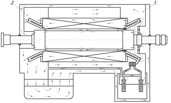
Figure 1.
Ventilation diagram of turbogenerator 325 MW (1—high pressure zone, 2—low pressure zone).
In general, turbogenerator cooling systems use shell-and-tube heat exchangers, where the cooling gas (hydrogen) circulates around the tubes and cooling water moves inside the tubes.
In order to increase the heat transfer on the gas side, finned tubes are often used. Fins allow a significant increase in the heat transfer area (3–4 times compared to conventional smooth tubes), which is especially important when working with low-density gases, such as hydrogen [,]. Among the types of finned tubes, the following designs are distinguished:
- -
- L-fin, LL-fin and Elfin, which are characterized by the mechanical attachment of the fins to the tube, which improves corrosion resistance and heat transfer [,];
- -
- Spiral (spiral-wound) fins, which ensure compactness and high heat transfer efficiency [];
- -
- Welded, which are characterized by high mechanical strength and excellent thermal conductivity [].
There are also alternative types of heat-exchangers, such as plate-fin, which are compact and lightweight, and plate-and-shell, which use a stack of plates inside a shell. Micro-channel heat-exchangers are less commonly used in cooling systems for large generators due to the technological complexity of their manufacture.
This study focuses on the justification for using a modernized heat exchanger design with finned tubes, while maintaining the nominal operating conditions of the TGV-325, including hydrogen outlet temperature and pressure. It is expected that the increase in heat transfer area due to finning will improve heat transfer without significantly increasing hydraulic losses.
Thus, the proposed approach ensures the preservation of the original operating parameters and opens up prospects for further optimization of cooling system designs in large electrical machines.
Figure 2 shows the calculation model of a gas cooler.
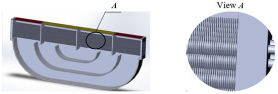
Figure 2.
Calculation model of a finned gas cooler.
In order to improve the performance characteristics, a bimetallic tube design is used —namely, brass tube—aluminum finning. This design provides sufficient protection of the tube material from corrosion. The issue of perfect contact between the coolants is of significant importance when using bimetallic finned tubes. In our case, the coolants are water—hydrogen vapor. The initial data of the gas cooler for analytical and three-dimensional calculation are given in Table 1, and the initial parameters of the gas cooler tube are given in Table 2.

Table 1.
Output parameters of the gas cooler.

Table 2.
Output parameters of the gas cooler tube.
2.2. Analytical Calculation Method for a Gas Cooler with Wire Fins
The main purpose of the analytical calculation is to determine the heat transfer reserve of the gas cooler of the Turbogenerator TGV-325.
The analytical calculation method given below can be used for gas coolers in which the cooling medium is water, air, hydrogen, or another diatomic gas. The method involves two consecutive calculations. The first is a preliminary calculation; its purpose is to select the optimal overall proportions and dimensions of the gas cooler, taking into account its design requirements, possible water and gas pressures, as well as the heat transfer reserve coefficient. The second is a verification calculation; its purpose is to determine the heat transfer reserve and the real values of water and gas pressure losses for the gas cooler, with specified overall dimensions.
2.2.1. Preliminary Analytical Calculation Method
In order to perform the preliminary calculation, the following parameters should be set: cold gas temperature, or gas temperature leaving the gas cooler tα volumetric flow rate of cold gas Qα; gas pressure p; water cooler inlet temperature tw; heat losses that need to be removed P; and the type of gas cooler tube and direction of water and gas flow. Below is a step-by-step procedure for preliminary calculation of a gas cooler.
The required water flow rate Qw through the gas cooler is determined based on a predefined water temperature rise of 4–5 °C, which corresponds to approximately 0.86–1.08 m3/h per 5 kW of losses. The exact value of the required water flow rate is calculated using Equation (7) provided below. In the future, the water flow rate can be specified by considering the logarithmic average temperature head.
We assume the speed of water movement in the gas cooler tubes Vw, based on the pressure capabilities of the water pump and the previous length of the tubes (Figure 3):
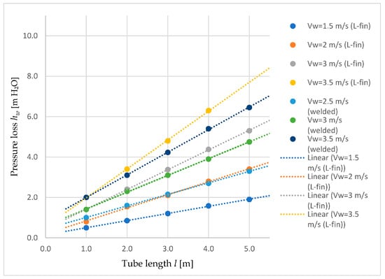
Figure 3.
Water pressure losses in a gas cooler depending on the length of the tubes and water velocity.
- -
- Welded Vw = 2.5–3.5 m/s;
- -
- L-fin Vw = 1.5–3 m/s
The number of gas cooler tubes is determined by the speed of water movement in the tubes Vw and the water flow rate per hour:
where qw—number of water courses; fw—cross-sectional area of the tube [cm2].
The gas overheating in the generator is determined by the formula:
where Cp—gas specific heat coefficient (for hydrogen—3.43 [kcal/(kg °C)]); Yα—weight gas consumption, determined by the formula [kg/s]:
where γα—the specific gravity of the cold gas is determined from Figure 4.
Yα = γα · Qα,
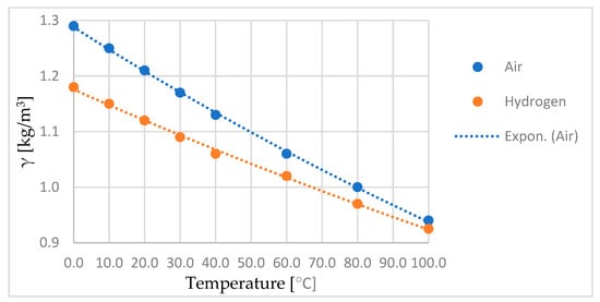
Figure 4.
Specific gravity of air and hydrogen at p0 = 760 mm Hg.
Overheating of water in the cooler is determined by the formula [°C]:
The water temperature rise is refined based on the final accepted water flow rates. For electric machines, the water overheating of should be 10–15% of the overheating of gas Tα.
Hot gas temperature is determined by the formula [°C]:
Hot water temperature is determined by the formula [°C]:
The mean logarithmic temperature difference for counterflow Δt [°C] is determined according to Table 3 and Figure 5, depending on the smallest and largest temperature heads between the working fluids. In Figure 5, Δt′ and Δt″ represent the first and second derivatives of the temperature difference, respectively. Their ratio Δt″/Δt′ reflects the rate of change in the heat transfer gradient and is used for refining the estimation of the logarithmic mean temperature difference in cases of non-uniform temperature distribution. This approach is based on the differential formulation
where Q—the heat flow; F—the heat exchange surface area.

Table 3.
Physical parameters of water along the saturation line.
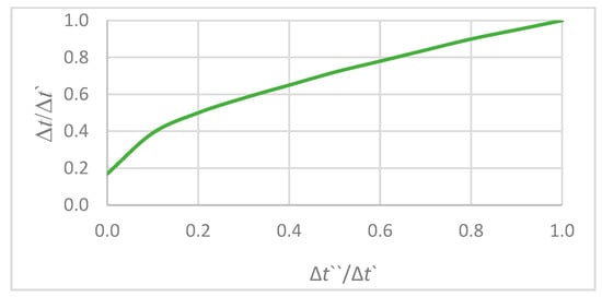
Figure 5.
Relationship between second and first derivatives of temperature difference (Δt″/Δt′) in counterflow configuration, used for refining logarithmic mean temperature difference (LMTD) estimation.
Specifying the Reynolds number Reα = 1500–2500, according to Figure 6, the heat transfer coefficient for hydrogen is determined K [kW/m2·°C], which provides a heat transfer margin of approximately 40%.
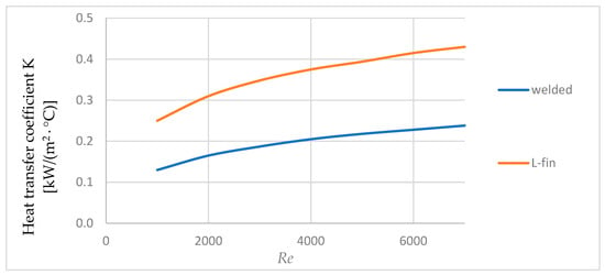
Figure 6.
Dependence of heat transfer coefficient on Reynolds number.
Gas cooler volume is determined by the formula [m3]:
where F0—surface of finned tubes that is wetted by gas, in 1 m3 of a gas cooler [m2/m3].
Gas flow rate in a narrow cross-section of the cooler gas, m/s:
where υ—is the coefficient of kinematic viscosity at the average gas temperature for hydrogen [m2/s]; τ—pitch of turns along the length of the tubes [m].
Gas cooler inlet area [m2]:
where qα—is number of gas strokes; Fi—live cross-section of 1 m2 of gas cooler [m2/m3]; tα avr—average gas temperature [°C], which is calculated by the formula:
Number of rows of tubes in the gas cooler is determined by the formula:
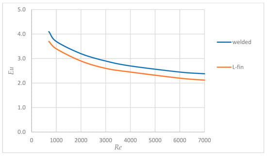
Figure 7.
Dependence of Euler’s number on Reynolds number.
Loss of gas pressure in the cooler [mm H2O]:
The permissible gas pressure loss is considered to be a pressure loss within the following limits:
- For large generators with a high-pressure network 5–10% of the pressure created by the compressor;
- For medium-sized machines and Hydrogenerators 10–20% of the total pressure spent on ventilation.
Number of tubes in a row of a gas cooler is determined by the formula:
Effective length of gas cooler tubes [m]:
where Si—transverse pitch of tubes [m].
If the pressure loss on the gas cooler hα is higher than the permissible one, it is necessary to choose the heat transfer coefficient K for a lower Reynolds number Re, taking into account the quadratic dependence of hα on Re. If hα is lower than the permissible one, then it is necessary to take K for a higher Reynolds number.
2.2.2. Methodology of Verification Analytical Calculation
In order to carry out the verification calculation, it is necessary to set the following parameters: outer diameter of the tube dout; internal diameter of the tube din; diameter of the finned tube D, м; effective length of the tube lef; total length of the tube l; pitch of turns along the length of the tube τ; surface of 1 m of the finned tube fα; number of tubes in a row nrow; number of rows mrow; number of cooler sections N; distance between the tubes in a row S1; distance between rows S2; number of water passes qw; number of gas passes qα; water flow rate Qw; cold gas flow rate at temperature tα Qα; temperature of the water entering the cooler tw; temperature of the gas leaving the cooler tα; gas pressure p; losses that need to be removed P. Below is a step-by-step procedure for the verification calculation of a gas cooler.
Heat dissipation surface of the entire cooler [m2]:
Narrow cross-section of the cooler [m2]:
The gas overheating in the generator is calculated by Equation (6), and the average temperature by Equation (14).
Gas speed in a narrow cross-section of the cooler [m/s]:
Reynolds number for gas flow in a narrow cross-section:
Nusselt criterion is as follows:
where l0—loop pitch along the outer circumference of the tube [mm]; h—fin height [mm].
Convective heat transfer coefficient:
where λ—is thermal conductivity coefficient of gas [kW/(m·°C)].
Heat transfer coefficient [kW/(m2·°C)]:
where fr—wire fin surface area per 1 m of a tube [m2/m]; —the coefficient determining the thermal resistance of wire finning is selected according to Figure 8; ; λm—thermal conductivity coefficient of wire fin material (for copper—0.375 [kW/(m·°C)]); and d0—fin wire diameter [m].
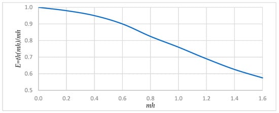
Figure 8.
Dependence of the thermal resistance coefficient on .
Total cross-sectional area of water flow for pipes [cm2]:
Water speed in tubes [m/s]:
Water pressure loss in the cooler [m H2O]:
The overheat value for water in the cooler specified by Equation (8), and the average water temperature calculated by the formula:
Reynolds number for water:
where υw—is kinematic viscosity coefficient for water at average temperature.
Heat transfer coefficient from the internal part of the gas cooler tubes [kW/m2·°C]:
where Pr—is Prandtl number for water at average temperature; λw—thermal conductivity coefficient for water at average temperature.
Heat transfer coefficient [kW/(m2·°C)]:
where f0m—the inner surface of a tube washed with water over a 1 m length [m2/m].
Average logarithmic temperature difference in counterflow [°C]:
Heat load of the cooler [kW/(m2·°C)]:
Heat transfer reserve (margin):
The heat transfer reserve shall be within 25–40%.
Euler criterion for gas flow:
The gas pressure loss is specified by Equation (16).
2.3. Numerical CFD Modeling of a Gas Cooler Taking into Account the Convective Heat Transfer Coefficient
Numerical simulation of turbulent hydrogen flow through a gas cooler was performed using the SolidWorks Flow Simulation 2013 software package, which allows for effective modeling of complex thermal–hydraulic problems for real engineering structures. Considering the nature of the problem (high Reynolds number, complex tube fin geometry, and steady-state flow conditions), the standard k-ε turbulence model was chosen for calculations.
The standard k-ε model is the most widely used in practical engineering problems due to its proven accuracy, computational stability, and adequate representation of averaged turbulent characteristics in high Reynolds number flows without significant flow separation zones [,]. This model is accurate enough to obtain integral and local heat transfer characteristics in tubular heat exchangers []. Despite the calculated Reynolds number being below the classical turbulence threshold, the geometry includes additional turbulence-inducing elements that generate turbulent flow. Therefore, using a turbulence model is appropriate and reflects actual conditions.
The following were used as calculation convergence conditions: minimum hydrogen temperature; average hydrogen temperature; and maximum hydrogen temperature and average water temperature.
To ensure maximum accuracy in the calculation of convective heat transfer, the heat transfer coefficient on the surface of the finned tubes was determined analytically using appropriate empirical correlations []. This analytically derived coefficient was then applied in the CFD model via boundary conditions, while the pressure loss between tube rows was emulated using a porous medium region (sponge element), forming a combined analytical–numerical modeling approach. This made it possible to establish correct boundary conditions and ensure consistency in comparison with analytical calculations. The following formulas were used to calculate the convective heat transfer coefficient:
where α—convective heat transfer coefficient; η—finning efficiency coefficient; h—finning height; λm1—thermal conductivity of the material; and δ1—thickness of a fin.
According to the design documentation, the dimensions of one section are 924 × 2990 mm. For the calculation model, we take a section with dimensions of 176 × 2990 mm, since the problem is symmetric along the length. A base mesh element size of 50 mm was selected for the numerical simulation using the finite volume method. During mesh generation, mesh control parameters were specified to refine the grid in regions containing small-scale elements (5–10 mm). Mesh refinement continued until further densification by 10% in characteristic regions resulted in changes in hydrogen pressure, temperature, and velocity of no more than 0.1%. Figure 9 and Figure 10 show the full boundary conditions for the gas cooler model and the calculation grid, respectively.
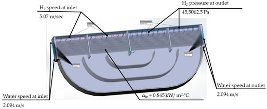
Figure 9.
Boundary conditions for gas cooler calculation.
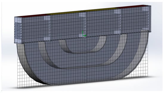
Figure 10.
Calculation grid for the gas cooler model.
As a result of CFD modeling, temperature fields were obtained for comparison with analytical data.
3. Results
3.1. Analytical and Numerical Results
Table 4 presents the results of the analytical calculation of the gas cooler.

Table 4.
Analytical calculation results.
In Figure 11, Figure 12 and Figure 13 the results of the numerical calculation of the gas-cooler in a three-dimensional formulation are presented.
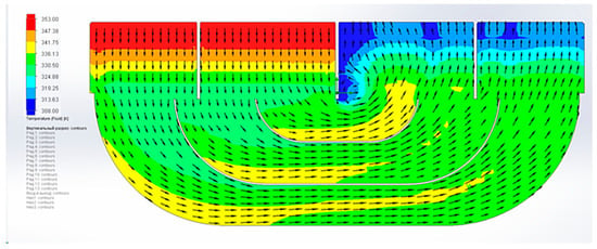
Figure 11.
Temperature diagram of the calculated cross-section.
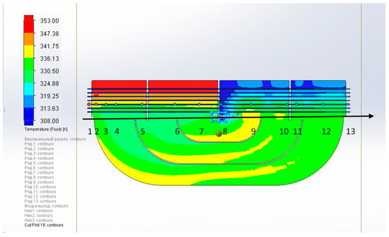
Figure 12.
Cooling water temperature along the gas cooler pipes.
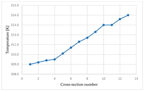
Figure 13.
Diagram of water temperature change.
As a result of the calculation, it was found that the discrepancy between the results of the analytical and numerical calculation does not exceed 10%, which confirms the reliability of the proposed combined method.
When analyzing the temperature fields in Figure 11, the unevenness of the temperature distribution was revealed, which is due to the peculiarities of the movement of hydrogen between the tubes and the specific geometry of the fins. As shown in Figure 12, the water temperature gradually increases along the length of the tubes, reaching ~45 °C at the outlet, which confirms the overheating of ~5 °C. These results are consistent with the studies described in the introductory part of this work. Thus, the data indicate further prospects for the constructive optimization of the gas cooler.
3.2. Experimental Validation
The simulation results were validated against experimental measurements from a full-scale hydrogen-cooled turbogenerator (type TGV-325), tested under steady-state conditions. These measurements were carried out by the authors and are detailed in previously published sources [,,]. Figure 14 shows the TGV-325-2AU3 turbogenerator with a power of 325 MW and rotor speed of 3000 rpm, manufactured by Ukrainian Energy Machines, on the manufacturer’s test bench.
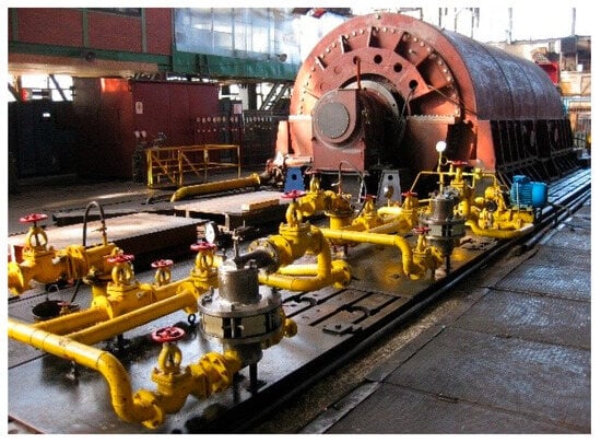
Figure 14.
Turbogenerator Type TGV-325-2AU3 on the test bench of the manufacturer.
The experimental validation was conducted following the main regulatory document in the field of electrical machines—standard DSTU IEC 60034-1:2019 [], which regulates the basic characteristics of electrical machines, and standard DSTU EN IEC 60034-3:2022 [], which contains special requirements for turbogenerators (synchronous generators driven by steam or gas turbines). During testing, temperature measurements were taken at the gas cooler inlet and at the gas cooler outlet. The measurement duration for the rated operating mode was 3–4 h. The gas temperature at the inlet and outlet of the gas coolers was also measured by permanently installed thermometers with a graduation of 1 °C. The tests were conducted with a cooling water flow rate through the gas coolers of 600 m3/h in accordance with the technical documentation. Water consumption was determined by the standard measurement system. The tests were conducted at an excess hydrogen pressure of 0.45 MPa in the turbogenerator housing, with hydrogen purity of not less than 98.7% in accordance with the requirements of the technical documentation.
Due to the stable operating conditions maintained throughout the test period, the temperatures measured remained constant, showing excellent agreement with the simulation predictions. Since this research combines both scientific and applied aspects, the experiment represents a performance test of the system using thermometers positioned in standard locations. The tests were conducted under steady-state conditions for the specified duration, where both ambient temperature and coolant (water) temperature remained constant throughout the experiment. Under these controlled conditions, the experimental temperature readings form a straight line [], and no deviation curve exists since all measured values coincide. The maximum temperature difference between simulation and measurements was within 0.5 °C, confirming the reliability of the proposed methodology.
4. Discussion
The paper proposes a combined method for thermal calculation of gas-coolers of Hydrogenerators, which is based on analytical correlations of heat-exchange and three-dimensional CFD modeling. The obtained results confirm the accuracy of this method: the discrepancy between analytical and numerical results is less than 10%. The achieved temperature of cooled hydrogen at the outlet (+40 °C) meets the requirements for the gas cooler of the Turbogenerator TGV-325. The superheat of the cooling water, in both calculations, is about 5 °C, which indicates the compliance of the calculation models.
The identified areas of uneven temperature distribution should be taken into account during further optimization of the design using modern design optimization methods, including genetic algorithms and artificial intelligence methods. Despite the non-uniform temperature distribution within the cooling duct cross-sections, the thermodynamic parameters of hydrogen remain consistent. However, this factor should be taken into account in future mechanical calculations of the housing components, where multidirectional deformation may lead to additional mechanical stresses. The proposed approach is practically significant and can be recommended for use in the design, modernization and further optimization of designs of high-power electric machines.
5. Conclusions
This study presents a combined analytical–numerical approach for evaluating the performance of hydrogen–water gas coolers in turbogenerators. The studied gas cooler has a total heat removal capacity of 3.8 MW (1266 kW per section).By combining classical heat transfer equations with three-dimensional CFD modeling using the standard k-ε turbulence model, the method demonstrated both high accuracy and practical applicability. The comparison between analytical and CFD results showed less than 10% discrepancy, validating the proposed methodology.
Key conclusions include the following:
- -
- The proposed method allows for accurate estimation of both integral and local thermal parameters of gas coolers with finned tubes.
- -
- The CFD results identified areas of non-uniform temperature distribution, which are critical for mechanical design considerations.
- -
- The cooling system meets the design requirements, including hydrogen outlet temperature and water overheating limits.
- -
- Despite computational simplicity, the standard k-ε model provided satisfactory accuracy due to the absence of strong flow separations.
The proposed methodology demonstrated less than 10% discrepancy between analytical and CFD results and was validated against operational performance data with temperature differences within 0.5 °C. These findings confirm the method’s accuracy for both integral and local thermal characteristics. Future work may involve applying optimization techniques, such as genetic algorithms or AI-driven modeling, to further improve the heat exchanger geometry and performance under variable load conditions.
Author Contributions
Conceptualization, D.K. and O.T.; methodology, O.T., B.S. and A.K.; software, S.K. and S.S. (Serhii Serhiienko); validation, M.A. and S.S. (Serhii Smakhtin); investigation, B.S.; resources, S.K., M.A. and A.K.; data curation, A.K.; writing—original draft preparation, B.S., M.A. and S.K.; writing—review and editing, O.T., M.A., S.K. and A.K. All authors have read and agreed to the published version of the manuscript.
Funding
This research received no external funding.
Data Availability Statement
The original contributions presented in this study are included in the article. Further inquiries can be directed to the corresponding author(s).
Conflicts of Interest
Author Anton Kovryga was employed by the company Joint Stock Company “Ukrainian Energy Machines”, Author Serhii Serhiienko was employed by the company Limited Liability Company “Kharkov Electric Machine-Building Plant”. The remaining authors declare that the research was conducted in the absence of any commercial or financial rela-tionships that could be construed as a potential conflict of interest.
References
- Palanichamy, R.; Nagaraj, P. Numerical simulation of laminar heat transfer in aluminium circular tube with internal longitudinal fins. Int. J. Model. Simul. 2010, 30, 204–210. [Google Scholar] [CrossRef]
- Pulagam, M.K.R.; Rout, S.K.; Muduli, K.K.; Syed, S.A.; Barik, D.; Hussein, A.K. Internal finned heat exchangers: Thermal and hydraulic performance review. Int. J. Heat Technol. 2024, 42, 583–592. [Google Scholar] [CrossRef]
- Bergman, T.L.; Lavine, A.S.; Incropera, F.P.; DeWitt, D.P. Fundamentals of Heat and Mass Transfer, 7th ed.; Wiley: Hoboken, NJ, USA, 2011; p. 1076. ISBN 13 978-0470-50197-9. [Google Scholar]
- Abdulrahman, G.A.Q.; Alharbi, S.M. Laminar and turbulent forced heat transfer convection correlations inside tubes: A review. arXiv 2024, arXiv:2401.02998. [Google Scholar] [CrossRef]
- Adanta, D.; Muhammad, N.M.; Fattah, I.M. Rizwanul. Comparison of standard k-ε and SST k-ω turbulence model for breastshot waterwheel simulation. J. Mech. Sci. Eng. 2020, 7, 39–44. [Google Scholar] [CrossRef]
- Mekki, B.S.; Langer, J.; Lynch, S. Genetic algorithm based topology optimization of heat exchanger fins used in aerospace applications. Int. J. Heat Mass Transf. 2021, 170, 121002. [Google Scholar] [CrossRef]
- Li, S.; Deng, Z.; Liu, J.; Liu, D. Multi-Objective Optimization of Plate-Fin Heat Exchangers via Non-Dominated Sequencing Genetic Algorithm (NSGA-II). Appl. Sci. 2022, 12, 11792. [Google Scholar] [CrossRef]
- Venkatesh, B.; Kiran, A.; Khan, M.; Rahmani, M.K.I.; Upadhyay, L.; Babu, J.C.; Narayana, T.L. Performance optimization for an optimal operating condition for a shell and heat exchanger using a multi-objective genetic algorithm approach. PLoS ONE 2024, 19, e0304097. [Google Scholar] [CrossRef] [PubMed]
- Krzywanski, J. A General Approach in Optimization of Heat Exchangers by Bio-Inspired Artificial Intelligence Methods. Energies 2019, 12, 4441. [Google Scholar] [CrossRef]
- Dong, H.; Ruan, L.; Wang, Y.; Yang, J.; Liu, F.; Guo, S. Performance of air/spray cooling system for large-capacity and high-power-density motors. Appl. Therm. Eng. 2021, 192, 116925. [Google Scholar] [CrossRef]
- Li, S.; Guo, J.; Lv, X.; Deng, T.; Cao, B.; Wang, J. Research on High-Pressure Hydrogen Pre-Cooling Based on CFD Technology in Fast Filling Process. Processes 2021, 9, 2208. [Google Scholar] [CrossRef]
- Shan, R.; Duan, J.; Zeng, Y.; Qian, J.; Dong, G.; Zhu, M.; Zhao, J. Study on the Thermal Field of a Hydro-Generator under the Effect of a Plateau Climate. Energies 2024, 17, 932. [Google Scholar] [CrossRef]
- Yan, W.M.; Li, H.Y.; Tsay, Y.L. Thermofluid characteristics of frosted finned-tube heat exchangers. Int. J. Heat Mass Transf. 2005, 48, 3073–3080. [Google Scholar] [CrossRef]
- Lindqvist, K.; Wilson, Z.T.; Næss, E.; Sahinidis, N.V. A Machine Learning Approach to Correlation Development Applied to Fin-Tube Bundle Heat Exchangers. Energies 2018, 11, 3450. [Google Scholar] [CrossRef]
- Saini, P.; Dhar, A.; Powar, S. Performance enhancement of fin and tube heat exchanger employing curved delta winglet vortex generator with circular punched holes. Int. J. Thermofluids 2023, 20, 100452. [Google Scholar] [CrossRef]
- Zhao, R.; Wang, Z.; Sun, Y.; Wang, F.; Huang, D. Effect of the Number of Circuits on a Finned-Tube Heat Exchanger Performance and Its Improvement by a Reversely Variable Circuitry. Appl. Sci. 2022, 12, 8960. [Google Scholar] [CrossRef]
- Kovryha, A. Creation of Methods for Three-Dimensional Modeling of the Thermal State of Brush-Holder Devices of Electric Generators to Ensure Power Increase of the Main Units. Ph.D. Thesis, National Aerospace University “Kharkiv Aviation Institute”, Kharkiv, Ukraine, 2025. Available online: https://khai.edu/assets/files/nauka/specradi/df-42/disertaciya_kovriga-z-pidpisom-s.pdf (accessed on 4 August 2025).
- Shestak, B. Analysis of gas cooler designs of existing turbogenerators. In Proceedings of the Innovative Approaches in Modern Science and Technology: Collection of Scientific Papers with Proceedings of the 2nd International Scientific and Practical Conference, International Scientific Unity. Lisbon, Portugal, 18–20 June 2025; pp. 246–252. [Google Scholar] [CrossRef]
- Shestak, B. Problem of cooling high-power turbogenerators. In Proceedings of the Research in Science, Technology and Economics: Collection of Scientific Papers of the 3rd International Scientific and Practical Conference, International Scientific Unity. Luxembourg, Luxembourg, 28–30 May 2025; pp. 335–336. [Google Scholar] [CrossRef]
- DSTU IEC 60034-1:2019; Rotating Electrical Machines. Part 1: Rating and Performance (IEC 60034-1:2017, IDT). Kyiv: DP “UkrNDNTs”. SE “UkrNDNC”: Kyiv, Ukraine, 2019. Available online: https://online.budstandart.com/ua/catalog/doc-page.html?id_doc=8353 (accessed on 6 August 2025).
- DSTU EN IEC 60034-3:2022; Rotating Electrical Machines. Part 3: Specific Requirements for Synchronous Generators Driven by Steam Turbines or Gas Turbines (EN IEC 60034-3:2020, IDT.; IEC 60034-3:2020, IDT). Kyiv: DP “UkrNDNTs”. SE “UkrNDNC”: Kyiv, Ukraine, 2022. Available online: https://online.budstandart.com/ua/catalog/doc-page?id_doc=102774 (accessed on 6 August 2025).
Disclaimer/Publisher’s Note: The statements, opinions and data contained in all publications are solely those of the individual author(s) and contributor(s) and not of MDPI and/or the editor(s). MDPI and/or the editor(s) disclaim responsibility for any injury to people or property resulting from any ideas, methods, instructions or products referred to in the content. |
© 2025 by the authors. Licensee MDPI, Basel, Switzerland. This article is an open access article distributed under the terms and conditions of the Creative Commons Attribution (CC BY) license (https://creativecommons.org/licenses/by/4.0/).