Abstract
This study presents a three-dimensional finite element (FE) analysis of the human foot bone structure under mid-stance loading during race walking. A subject-specific biomodel comprising 26 bones and over 40 ligaments was reconstructed from computed tomography (CT) data using Materialise Mimics Research 21.0 and 3-Matic Research 13.0, and subsequently analyzed in ANSYS Workbench 2024 R1. The model included explicit cortical, trabecular, and ligamentous volumes, each assigned linear-elastic, isotropic material properties based on biomechanical literature data. Boundary conditions simulated the mid-stance phase of race walking, applying a distributed plantar pressure of 0.25 MPa over the metatarsal and phalangeal regions. Numerical simulations yielded maximum total displacements of 0.00018 mm, maximum von Mises stresses of 0.171 MPa, and maximum strains of 2.5 × 10⁻⁵, all remaining well within the elastic range of bone tissue. The results confirm the model’s numerical stability, geometric fidelity, and capacity to represent physiologically realistic loading responses. The developed framework demonstrates the potential of high-resolution, image-based finite element modelling for investigating stress–strain patterns of the foot during athletic gait, and establishes a reproducible reference for future analyses involving pathological gait, orthotic optimisation, and musculoskeletal load assessment in sports biomechanics.
1. Introduction
Walking, or athletic walking, is a sport that demands precise biomechanics and rigorous postural control from the human body. Unlike running, during race walking the athlete must maintain constant contact with the ground and avoid losing contact in both phases of the gait cycle, which implies a highly controlled and repetitive movement pattern [1,2]. This particular characteristic generates a different type of overload on the musculoskeletal structure, especially the foot.
The human foot is a complex and highly specialised anatomical structure that performs fundamental functions in locomotion. It supports body weight, absorbs impacts, transmits loads, and facilitates movement by continuously interacting with external forces. These functions are especially demanded during sports activities such as high-performance walking, where the loads applied to the musculoskeletal system increase considerably and their dynamic distribution constantly changes throughout the gait cycle [3]. Understanding how the foot reacts to these loads is crucial not only for preventing injuries but also for designing footwear, orthotics, and personalised medical treatments. Gait analysis enables the evaluation of multiple parameters that characterise the dynamic behaviour of the foot and other joints in the body. These parameters include kinematics (such as range of motion), spatiotemporal parameters (stride, cadence), and kinetics (joint and ground reaction forces) [4]. However, to better understand the internal impact of these forces on the bone structures and ligaments of the foot, computational models that faithfully represent their anatomy and allow for numerical simulations are necessary. The use of three-dimensional modelling and simulation tools, utilising the Finite Element Method (FEM), has grown exponentially in the study of biological structures [5,6]. These techniques provide a non-invasive, accurate, and reproducible method for analysing the mechanical behaviour of complex organs under various loading conditions. This task is challenging to achieve with experimental methods alone [7,8]. In particular, FEM enables the calculation of detailed distributions of stresses, deformations, and displacements, facilitating the structural and functional evaluation of biological systems, such as the foot.
Image-based FE studies of the foot span from simplified segment/forefoot representations to subject-specific whole-foot reconstructions. Systematic reviews emphasise that modelling choices (geometry fidelity, ligaments, materials, contact) strongly affect predicted pressures and stress fields and should be reported transparently [5]. Simplified anatomical abstractions facilitate meshing and faster analyses but may bias plantar pressure and stress predictions compared with geometrically accurate reconstructions [9]. Recent works address clinical or sport-specific scenarios (e.g., stress distributions in midfoot conditions, arthrodesis constructs, or running contact angles) and show the usefulness of FE for hypothesis testing under controlled loads [6,10,11]. At the same time, coupled frameworks that integrate footwear or neuromuscular control provide broader functional realism (e.g., foot–shoe complexes, rocker mechanisms, mobile arch/toe joints), while operating with assumptions that may abstract ligament anatomy or increase parameter identifiability demands [12,13,14]. Reviews on insole prescription highlight the value of in silico pipelines to personalise interventions [15], and data-driven approaches are emerging to link individual morphology and loading with bone stress risk in athletes [16]. Overall, the literature reflects a spectrum: from efficient, simplified FE models suitable for design iteration, to high-fidelity, image-based assemblies that preserve detailed osteoligamentous geometry, each with strengths (speed vs. anatomical realism) and limitations (potential bias vs. computational cost) [5,9,10,11,12,13,14,15,16].
The main contribution of this work lies in the construction of a novel and complete three-dimensional model of the human foot bone structure, with a level of detail that surpasses models commonly reported in the literature. This model not only includes all 26 bones of the foot, differentiating between cortical and trabecular tissue, but also incorporates more than 40 anatomically positioned ligaments [17], providing a comprehensive representation of the foot’s support system. This feature makes the model a valuable scientific tool with potential applications in orthopaedic studies, sports performance analysis, medical device design, and clinical simulations [18]. Unlike previous approaches that model only foot segments or employ geometric simplifications to reduce analysis complexity [9,12], this study opted to capture the actual geometry and structural composition of the human foot with high fidelity. This level of precision enables the realistic simulation of the foot’s internal responses to the characteristic loads of the gait cycle, thereby constituting a novel tool in the fields of sports and clinical research. The main contribution of this study lies in the construction of a complete biomodel, obtained from high-resolution computed tomography (CT) of a healthy adult and processed using specialised software (Materialise Mimics and 3-Matic) for subsequent numerical analysis in ANSYS [13,19]. Realistic boundary conditions representing mid-stance and a representative plantar load were applied, from which displacements, strains, and stresses were evaluated at the structural level. The objective is to verify the model’s viability to represent foot mechanics under controlled athletic loading while documenting a reproducible pipeline. That is, the proposed model is intended to serve as a reliable framework for studying the mechanical response of the foot under controlled race-walking loads and for establishing a reproducible basis for future biomechanical investigations. This foundation can facilitate subsequent research focused on the simulation of pathological conditions [14], the analysis of sport-specific injuries in race walkers, and the evaluation of surgical interventions [10]. Furthermore, it can support the design of personalised biomechanical solutions such as sports insoles [15] and contribute to the development of practical applications in high-performance and clinical biomechanics [11,16].
2. Materials and Methods
The modelling pipeline comprised image-based segmentation, geometric reconstruction, volumetric meshing, and finite element (FE) analysis. Materialise Mimics Research 21.0 and 3-Matic Research 13.0 (Materialise NV, Leuven, Belgium) were used for image processing and geometry preparation, and ANSYS Workbench 2024 R1 (Ansys Inc., Canonsburg, PA, USA) for numerical simulation. These tools were selected for their robust integration in medical-image-based modelling workflows and their demonstrated ability to preserve anatomical detail while ensuring compatibility for FE analysis. ANSYS Workbench was preferred for its solver accuracy, stability under complex contact conditions, and reliability in biomechanical structural analyses. Geometries were handled in millimetres and mechanical quantities in MPa to ensure consistency across all stages.
2.1. Image Acquisition and Segmentation
A high-resolution computed tomography (CT) scan of the right foot of a healthy 30-year-old male subject, 1.65 m tall and weighing 63 kg, was used. The images obtained in DICOM format were imported into Mimics software (Materialise), where detailed segmentation of the 26 bones of the foot was performed [20]. Each structure was individualised, differentiating between cortical and trabecular tissue, by creating separate masks. Segmentation was performed using the three orthogonal views (axial, sagittal, and coronal), and adjustable stroke control was employed to precisely delineate the contours in approximately 80 slices per view, thereby preserving the anatomical morphology of each bone with high fidelity [21,22] (Figure 1).
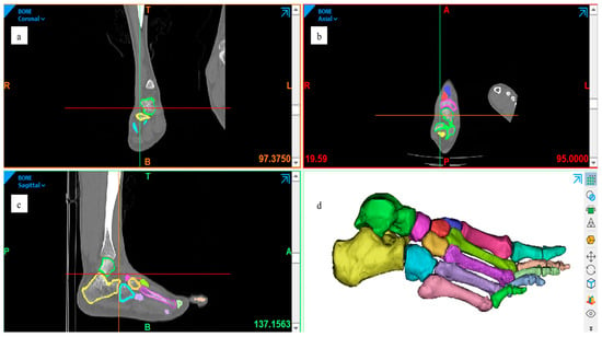
Figure 1.
Segmentation process of the right foot from the CT dataset, performed in Materialise Mimics (Materialise NV, Leuven, Belgium). The three orthogonal planes illustrate the same segmentation workflow viewed from different orientations: (a) coronal, (b) axial, and (c) sagittal. These views collectively demonstrate the consistency of bone masking and the preservation of cortical–trabecular boundaries across planes. (d) Three-dimensional reconstruction preview combining all segmented structures. All panels are author-generated from the dataset described in Section 2.1.
For the reconstruction of trabecular bone, the automatic cavity-filling tool was applied, enabling the creation of internal masks within the hollow bones. In total, 52 segmentation masks were generated, 26 corresponding to cortical compartments and 26 to trabecular structures. This duplication increased the model’s complexity but ensured complete anatomical differentiation and facilitated subsequent material assignment and meshing. As a result, the final model includes both trabecular and cortical tissue (Figure 2).
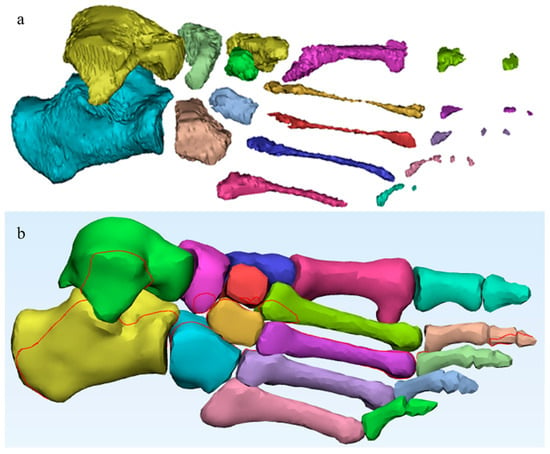
Figure 2.
Segmented bone structures obtained from the CT dataset, processed in Materialise Mimics (Materialise NV, Leuven, Belgium). (a) Trabecular bone: author-generated internal masks and volumes created using the cavity-filling workflow; (b) Cortical bone: author-generated outer masks and volumes reconstructed from the same dataset.
2.2. Ligament Reconstruction
Ligament reconstruction was performed using advanced tools such as the Thin Structure tool, which allows the drawing of thin structures that simulate the actual anatomical path of ligaments. This, combined with detailed anatomical references and reference images from the tomographic section, ensured a realistic representation of the connections between bones and the passive support of the foot [23] (Figure 3). The use of such advanced tools underscores the innovation and advancement in the field of anatomical modelling.
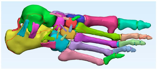
Figure 3.
Foot model with all ligaments added. Author-generated volumetric assembly of cortical bone, trabecular bone, and ligaments reconstructed from CT data and anatomical references.
Ligaments, key stabilising structures of foot biomechanics, are the crucial anatomical elements that join and support the bones of the foot. They serve as the vital link between the 26 bones, providing stability to the joints and enabling fluid movements. Their complex anatomy [24] underscores the challenge in understanding them. The Finite Element Method, a powerful research tool, has been harnessed to delve into the biomechanics of these ligaments and bones in the foot, as well as in orthopaedic applications. However, the models of the foot ligaments developed using finite element analysis have varied significantly, presenting different configurations, mainly due to their complex three-dimensional geometry, material properties, and boundary conditions [25].
A total of forty-four ligaments were reconstructed to provide realistic joint constraints and anatomical connectivity between the bones of the foot (Table 1). Although not visible in the CT dataset, most of these ligaments were modelled manually based on classical anatomical descriptions. Specifically, the model included the talocalcaneal complex (lateral, medial, posterior, interosseous, and cervical ligaments), calcaneocuboid ligaments (dorsal, short plantar, and long plantar), talonavicular and talonaviculocuneiform ligaments, cuneonavicular and intercuneiform ligaments, cuboideocuneiform and cubonavicular ligaments, as well as the spring ligament (calcaneonavicular plantar). At the forefoot level, the model incorporated the Lisfranc (tarsometatarsal) ligaments, metatarsophalangeal plantar ligaments, and interphalangeal plantar ligaments. These last three groups were reconstructed by following the anatomical spaces visible in the CT dataset, thereby combining direct image-based references with anatomical guidance. This reconstruction strategy ensured full osteoligamentous continuity and allowed the model to replicate the mechanical stabilisation functions of the native foot ligaments.

Table 1.
Ligaments reconstructed in the finite element foot model.
2.3. Three-Dimensional Reconstruction
The segmented set was exported to 3-Matic (Materialise), where the complete model was three-dimensionally reconstructed. Global smoothing (Smooth) and local smoothing (Local Smoothing) were applied to remove imperfections and correct surface irregularities resulting from manual segmentation. Volumetric meshing tools were then used to generate internal volumes for each structure, ensuring the geometric quality of each component, the geometric continuity of the model, and its viability for finite element analysis. In this way, each bone and ligament was assigned an internal volume to facilitate subsequent structural analysis. The final model, composed of cortical, trabecular, and ligamentous structures, was converted to STL format. This format is compatible with ANSYS Workbench, the software used for numerical simulation. Furthermore, this format preserves the three-dimensional geometry of the segmented objects and allows for their integration without assembly errors.
2.4. Model Import and Material Assignment
The STL files were imported into the ANSYS Workbench structural analysis environment, and specific mechanical properties were established for each biological component of the model: cortical bone, trabecular bone, and ligaments. The assigned mechanical properties were based on data from the literature [26,27,28,29,30,31,32,33], as presented in Table 2. These included Young’s modulus, Poisson’s ratio, and yield strength for each material. All tissues were modelled as linear elastic and isotropic, as commonly adopted in baseline finite element studies of foot biomechanics. Although yield strength values were reported in Table 2, they were not incorporated into the constitutive law; instead, these values were included only as reference thresholds to verify that computed stresses remained within the elastic regime. This approach ensured numerical stability while allowing comparison with published strength limits of cortical and trabecular bone. Properties were manually assigned to each component, and the correspondence between each anatomical region and its corresponding mechanical property was verified. This precise assignment was essential for obtaining realistic results in the subsequent structural analysis.

Table 2.
Mechanical properties of the biological components of the foot.
2.5. Boundary Conditions and Loading
Considering that the positioning of the foot and the types of constraints imposed on the model significantly affect the results in each case study [34], boundary constraints were applied as Fixed Supports on the upper surfaces of the foot and around the calcaneus. These constraints simulate the behaviour of the foot during the mid-phase of the athletic gait cycle, when the heel is in firm contact with the ground and most of the body weight is supported [35] (Figure 4).
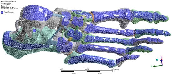
Figure 4.
Boundary conditions. Author-generated FE setup in ANSYS showing fixed supports applied to superior surfaces and calcaneus to represent mid-stance loading.
Regarding loading, a distributed pressure of 0.25 MPa was applied to the plantar region [36], corresponding to the middle phase of the athletic gait cycle. This load was selected because it represents an average pressure value recorded in athletes during foot contact with the ground [37] (Figure 5). The plantar pressure was not applied as a single concentrated load but as a distributed surface load over the metatarsal heads and phalangeal regions, which correspond to the areas of maximum ground contact during mid-stance [38] (Figure 6).
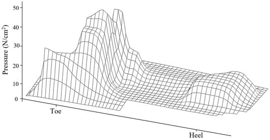
Figure 5.
Typical plantar pressure pattern during gait cycle. Author-created schematic, generated de novo with a generative graphic tool, conceptually based on McGinnis [37]; no original artwork reproduced.
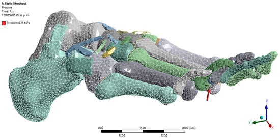
Figure 6.
Application of load to the plantar region. Author-generated FE setup showing distributed pressure applied to metatarsal heads and phalanges as defined in Section 2.4.
Although Figure 6 shows a heterogeneous plantar pressure distribution, the adopted simplification corresponds to the average pattern typically measured in athletes at this gait phase, with a uniform 0.25 MPa pressure representative of experimental reports. This conservative approach ensured stability of the baseline model and facilitated reproducibility. In future extensions, the model will be enriched with subject-specific plantar pressure maps to reproduce heterogeneous loading across the entire plantar surface.
2.6. Discretisation and Computational Parameters
The finite element discretisation was generated in ANSYS Workbench using adaptive sizing (resolution level 2) and smooth transition. Quadratic tetrahedral elements were employed, as they are suitable for representing irregular and complex anatomical geometries. Local refinement was applied at the contact and hinge areas (Figure 7), where higher stress concentrations were expected. The final mesh consisted of 59,144 elements and 113,159 nodes, ensuring sufficient refinement to capture the geometry of the cortical, trabecular, and ligamentous structures. Mesh quality was assessed using ANSYS default mechanical criteria, confirming the absence of critical errors in the generated elements.
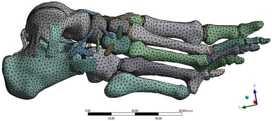
Figure 7.
Mesh discretisation. Author-generated tetrahedral mesh with local refinement at contacts and ligament insertions; prepared in ANSYS for structural analysis.
The selected analysis type was structural statics, with a convergence criterion based on total energy. Displacements, strains, and stresses (von Mises, principal, and shear) were evaluated. The simulation was run on a high-performance workstation with 10 cores and 16 GB of RAM, with a total calculation time of approximately 10 min.
2.7. Description of Computational Techniques
The computational workflow integrated image-based segmentation, geometric reconstruction, and structural analysis within a unified finite element (FE) pipeline. Image segmentation and anatomical masking were performed in Materialise Mimics Research 21.0 (Materialise NV, Leuven, Belgium), while surface reconstruction, smoothing, and ligament path definition were carried out in 3-Matic Research 13.0 from the same developer. The resulting geometries were then imported into ANSYS Workbench 2024 R1 (Ansys Inc., Canonsburg, PA, USA) for FE processing. All stages were configured to preserve anatomical fidelity and ensure element compatibility across meshes.
Within ANSYS, bonded contacts were defined between bones and ligaments, and automatic quadratic tetrahedral meshing with local refinement at high-curvature and ligament insertion regions was employed. Mesh quality and convergence were verified according to solver criteria to guarantee numerical stability. The analyses were performed under a static structural scheme with energy-norm convergence, evaluating displacements, strains, and stresses in the linear-elastic regime. Simulations were executed on a workstation equipped with an Intel® Core™ i7-1355U processor (10 cores, 12 threads, up to 5.0 GHz), 16 GB RAM, and Windows 11 (64-bit), with average runtimes of approximately 10 min per case.
By specifying software versions, meshing strategy, convergence criteria, and hardware configuration, the proposed methodology ensures reproducibility and allows other researchers to replicate or extend the modelling pipeline using subject-specific data.
2.8. Image Provenance and Permissions
All figures were generated by the authors from the CT dataset described in Section 2.1 and from the finite element (FE) analyses reported in Section 2.3, Section 2.4 and Section 2.5 using Materialise Mimics, 3-Matic, and ANSYS Workbench. Figure 6 is an author-generated schematic created de novo with a generative graphic tool to illustrate the typical plantar pressure distribution; it is conceptually based on McGinnis [37] but does not reproduce, trace, or scan any original artwork. Where external material is adapted, the source is cited in the caption and permissions will be obtained if required by the publisher. All colour bars display the actual numeric ranges reported in the text/tables, and viewing angles were chosen solely for clarity.
3. Results
The numerical analysis was configured by selecting the mechanical parameters of interest in ANSYS, such as displacements, deformations, and stresses. These evaluations were conducted to characterise the structural behaviour of the model under the applied load, and graphical results were obtained from these evaluations. All parameters assigned for evaluation in this test are shown in Table 3, along with the values of the results obtained.

Table 3.
Evaluated mechanical parameters and obtained values.
3.1. Displacements
The maximum total displacement was 0.00017986 mm, located primarily in the forefoot region, near the phalanges. This extremely low value indicates a rigid and stable response of the model under the applied load. The displacement components along the x, y, and z axes were also small, with maximum values of 8.16 × 10⁻⁵ mm, 4.53 × 10⁻⁵ mm, and 1.64 × 10⁻⁴ mm, respectively, without compromising the structural integrity of the system. The hindfoot regions, especially the calcaneus, showed zero or negligible displacements, consistent with their anchoring function during the mid-gait cycle.
3.2. Strains
Total strains reached a maximum value of 2.49 × 10⁻⁵, with distributions localised in the transition zones between bones and ligaments. Strains were particularly significant in the y and z directions, where minimums of up to –2.14 × 10⁻⁵ and –2.32 × 10⁻⁵ were recorded, respectively. These magnitudes remain within the elastic range of bone tissue, with no evidence of permanent deformation, suggesting that the structure is capable of adequately supporting the simulated load without functional impairment.
3.3. Stresses
The von Mises stresses were distributed homogeneously, with a maximum value of 0.171 MPa, which is well below the yield strengths of cortical bone (100 MPa) and trabecular bone (5 MPa). This result confirms that the model operates within the elastic regime in all simulated elements. Additionally, the maximum shear stresses were found at 0.088 MPa, while the minimum principal stress reached –0.348 MPa. These stresses, although negative in some areas, do not pose a significant structural risk, as they do not approach critical values that would compromise the system’s stability.
3.4. Visual Analysis
The images generated by ANSYS visually confirm the distribution of the evaluated parameters. Figure 8 shows the location of maximum displacements at the distal extremities of the model, while Figure 9, Figure 10 and Figure 11 illustrate the regions of greatest stress and strain, all consistent with the most anatomically mobile areas of the foot. The four primary outcomes capture complementary aspects of the structural response: total displacement (global kinematics), total strain (deformation measure), von Mises stress (distortion-driven failure index), and maximum principal stress (tensile damage proxy). Hotspots consistently appeared at the metatarsal necks and cuneiform–metatarsal joints under the applied mid-stance loading, reflecting the regions most exposed to mechanical demand. Additional parameters, such as maximum shear stress and minimum principal stress, showed similar spatial trends and were therefore relocated to the Supplementary Material for completeness. These visualisations validate the consistency of the mesh, the assigned mechanical properties, and the implemented boundary conditions.
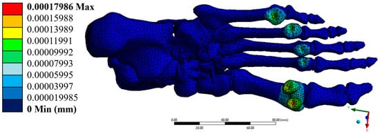
Figure 8.
Total displacement (mm). Author-generated FE results for the model described in Section 2.4, Section 2.5 and Section 2.6; colour bar shows the actual range reported in Table 3.
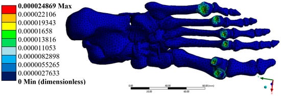
Figure 9.
Total strain (dimensionless). Author-generated FE results under mid-stance load; values match those reported in Table 3.
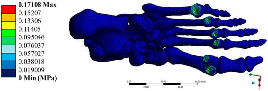
Figure 10.
Von-Mises Stress (MPa). Author-generated FE results; ranges correspond to Table 3.

Figure 11.
Maximum principal stress (MPa). Author-generated FE results; ranges correspond to Table 3.
4. Discussion
The present work introduces a high-fidelity three-dimensional FE model of the human foot, integrating cortical bone, trabecular bone, and over forty anatomically positioned ligaments derived from high-resolution CT and processed with Materialise Mimics and 3-Matic. Unlike models that represent only partial foot structures or employ simplified geometries, the proposed model preserves the detailed morphology of each anatomical component, enabling realistic simulation of the foot’s mechanical behaviour during the mid-stance phase of race walking. Although the computed displacements were extremely low, this outcome reflects the intentionally constrained configuration of the model, which excludes soft tissues and employs a conservative static load representative of mid-stance phase. These boundary conditions result in a rigid response consistent with the expected elastic limits of cortical bone. Such minimal deformations confirm the structural coherence of the assembly and validate its suitability for subsequent extensions involving dynamic loading or soft-tissue integration.
4.1. Original Contribution and Significance
The novelty of this study lies in the complete anatomical integration of all skeletal and ligamentous structures into a single volumetric FE assembly suitable for high-resolution stress–strain analysis. Segmentation was performed slice-by-slice in three orthogonal planes, cortical and trabecular compartments were explicitly differentiated, and ligament bundles were reconstructed volumetrically. Material properties for cortical bone, trabecular bone, and ligaments were assigned from peer-reviewed sources, and the resulting displacements, strains, and stresses remained within the elastic range, supporting the mechanical credibility of the predicted fields. This fidelity—full-foot geometry with trabecular/cortical separation and explicit ligament volumes—supports credible analyses of internal load sharing [39], with direct relevance to sports biomechanics, orthopaedic device design, and pre-surgical planning.
4.2. Relation to Previous Work
Prior studies frequently considered partial segments or simplified geometries, which can bias pressure and stress predictions; for example, forefoot-only models have shown meaningful deviations from CT-based geometries in plantar pressure fields [9]. Earlier full-foot frameworks established important precedents for image-based modelling and footwear/soft-tissue effects during standing, but typically without explicit volumetric ligaments or trabecular–cortical separation [40]. Systematic and scoping reviews emphasise broad variability in modelling choices and clinical aims across foot FE studies, underscoring the need for transparent, reproducible pipelines [5]. Subject-specific dynamic frameworks that couple image-based FE with musculoskeletal loads provide comprehensive simulations but introduce numerous additional parameters with nontrivial identifiability [35]. More recently, predictive multi-segment foot models for full-body gait dynamics advance control and actuation realism yet operate with segment-level abstractions of ligamentous anatomy [41]. In contrast, the present model preserves whole-foot osteoligamentous anatomy with explicit volumetric ligaments and trabecular/cortical separation while deliberately retaining conservative, well-defined mid-stance loading and boundary conditions, thereby offering a transparent, reproducible baseline on which added complexities can be layered.
Compared with prominent subject-specific dynamic models [35] and clinical FE pipelines for midfoot pathology [6], this contribution differs in three practical aspects. First, it integrates all 26 foot bones with explicit separation of cortical and trabecular compartments reconstructed from CT, whereas prior dynamic frameworks commonly treat “bone” as a single solid without compartmentalisation to prioritise speed and coupling with gait data [35]. Second, more than forty ligaments were reconstructed as volumetric thin structures following anatomical pathways (and, for tarsometatarsal and phalangeal groups, guided directly by the CT inter-osseous spaces), rather than represented by tension-only truss or spring elements that are typical in many dynamic or clinical models [6,35]. Third, the modelling pipeline is documented for reproducibility (segmentation masks, cortical/trabecular partition, ligament set, meshing and solver settings), enabling reuse as a baseline elastic benchmark before introducing subject-specific ground contact, muscle forces or transient loads. This positioning complements dynamic, subject-specific studies (such as Akrami et al., who coupled FE with motion capture, GRFs and muscle forces, but showing high sensitivity to boundary definitions) by providing a geometry-faithful, shareable starting point that minimises under-constrained parameters [35].
4.3. Potential Use by Other Researchers
The geometry (STL parts), materials table, named selections for plantar loading, and ANSYS project settings constitute a portable package. With these assets, other groups can reproduce the baseline elastic response under mid-stance, substitute measured plantar pressure maps or ground reaction forces, introduce subject-specific properties, and augment the assembly with explicit foot–ground contact, soft tissues, and muscle forces for dynamic simulations. The model thereby serves both as a benchmark and as a starting point for subject-specific analyses.
From a practical perspective, the preparation of the materials, methodology, and results required approximately five months. The CT acquisition and preprocessing were completed within the first month, segmentation and 3D reconstruction (including ligament modelling) extended over about three months, and the remaining month was devoted to meshing, assignment of material properties, and execution of the finite element analyses. This time frame provides a useful reference for other researchers who intend to reproduce or extend the present modelling pipeline.
4.4. Limitations and Future Work
This first report intentionally adopts linear-elastic isotropic tissues and bonded interfaces and applies a uniform mid-stance plantar pressure without explicit foot–ground contact, muscle forces, or time dependence. These simplifications prioritised stability, transparency, and reproducibility of the baseline elastic response.
Although the present study focuses on the mid-stance phase of race walking through a static structural simulation, it must be emphasised that this analysis represents a descriptive instant of a dynamic movement. A complete analysis ultimately requires dynamic explicit algorithms and explicit foot–ground contact. These approaches were deliberately excluded at this stage but will be incorporated in future work together with frictional contact, transient dynamic loads, muscle actuation, and orthotropic tissue properties, allowing a more comprehensive replication of race-walking biomechanics.
Experimental validation was not conducted in this study; instead, verification was ensured by convergence checks of the finite element solution and by comparing the obtained stress–strain ranges with published values for cortical and trabecular bone. The computed values remained well within the elastic regime and considerably below reported yield thresholds, supporting the internal consistency of the model. Nevertheless, future extensions will integrate validation against plantar pressure measurements, motion capture data, and in vivo kinematics to reinforce external accuracy.
Minor inaccuracies may result from manual ligament reconstruction, particularly for structures not clearly visible in the CT dataset. Likewise, the smoothing and meshing processes, while necessary for finite element compatibility, could slightly reduce local anatomical detail. These effects are minimal and do not compromise the overall biomechanical interpretation of the model.
Despite these limitations, the present framework already provides a reproducible and anatomically detailed baseline that can serve as a benchmark for subsequent methodological extensions and subject-specific applications.
5. Conclusions
The results of the numerical analysis demonstrate that the developed model faithfully represents the bone structure of a healthy human foot under loading conditions corresponding to the mid-stage of athletic walking. The values obtained for displacements, stresses, and strains were minimal. They remained well below the yield strengths of cortical and trabecular bone tissue, confirming that the model behaves within the elastic regime and maintains its structural integrity. The maximum total displacement recorded was 0.00017986 mm, and the Von Mises equivalent stress reached 0.171 MPa, which is far from the critical threshold for the biological materials modelled. The unit strains, with a maximum of 2.49 × 10⁻⁵, were primarily concentrated in transition zones between bone structures, which is biomechanically expected and reinforces the structural validity of the model. The model was constructed from high-resolution computed tomography (CT) scans, enabling a detailed geometric reconstruction of the 26 bones that comprise the human foot.
Additionally, more than 40 ligaments with distinct mechanical properties were incorporated, accurately representing the foot’s passive support system. Material allocation based on specialised literature (cortical, trabecular, and ligamentous) along with a plantar loading representative of athletic gait allowed for a realistic simulation of the foot’s biomechanical behaviour under dynamic conditions. The use of the Finite Element Method (FEM) in ANSYS proved to be a robust and effective tool for evaluating the model’s structural properties. Boundary conditions, applied to the upper part of the foot and the calcaneus, facilitated a realistic representation of foot–ground interaction during athletic walking. Since stresses and strains were kept within physiologically safe ranges, this biomodel can be considered a solid foundation for future, more complex research. Its potential applications include the study of pathological conditions, the optimisation of orthotic insoles, the design of specialised athletic footwear, and the evaluation of surgical interventions. In conclusion, the proposed model meets the geometric, material, and mechanical requirements necessary to represent the foot’s bone structure under dynamic conditions accurately. Its numerical validity and anatomical fidelity make it a reliable tool for advanced biomechanical studies in sports and clinical settings.
Supplementary Materials
The following supporting information can be downloaded at: https://www.mdpi.com/article/10.3390/computation13110249/s1, Figure S1: Maximum shear stress (MPa); Figure S2: Minimum principal stress (MPa).
Author Contributions
Conceptualization, E.J.R.-G. and G.U.-S.; methodology, E.J.R.-G., J.A.G.-N. and J.R.G.-I.; software, E.J.R.-G. and Y.Y.R.-C.; validation, E.J.R.-G. and M.d.l.L.S.-H.; formal analysis, E.J.R.-G. and R.I.Y.-A.; investigation, E.J.R.-G. and M.N.R.-M.; resources, G.U.-S., B.R.-Á. and G.M.U.-C.; data curation, E.J.R.-G.; writing—original draft preparation, E.J.R.-G.; writing—review and editing, G.U.-S., B.R.-Á. and G.M.U.-C.; visualization, E.J.R.-G.; supervision, G.U.-S., B.R.-Á. and G.M.U.-C.; project administration, G.U.-S.; funding acquisition, G.U.-S. and B.R.-Á. All authors have read and agreed to the published version of the manuscript.
Funding
This research was supported by a doctoral fellowship from the Secretaría de Ciencia, Humanidades, Tecnología e Innovación (SECIHTI, Mexico) through the Instituto Politécnico Nacional (IPN). No specific grant number was assigned to this funding.
Institutional Review Board Statement
The study was conducted in accordance with the Declaration of Helsinki. Ethical review and approval were waived, as the work involved a single healthy adult volunteer and consisted exclusively of non-invasive CT imaging followed by computational modelling.
Informed Consent Statement
Written informed consent was obtained from the volunteer involved in the study for the acquisition of the CT scan and its use for research purposes.
Data Availability Statement
The CT dataset contains identifiable human data and is not publicly available due to privacy restrictions. De-identified derived data are available from the corresponding author upon reasonable request. No third-party data were used.
Acknowledgments
The authors gratefully acknowledge the Instituto Politécnico Nacional and the Secretaría de Ciencia, Humanidades, Tecnología e Innovación for supporting this research.
Conflicts of Interest
The authors declare that no one has potential conflicts of interest nor will benefit financially from the results of this study. All figures are original and author-generated from the study’s data and simulations, except Figure 6, which is an author-created schematic inspired by concepts in McGinnis [37] and does not reproduce any copyrighted artwork; permissions will be sought should the publisher deem them necessary.
References
- Cairns, M.A. A Biomechanical Analysis of Racewalking Gait. Master’s Thesis, Boston University, Boston, MA, USA, 1984; pp. 1–2. [Google Scholar]
- Pavei, G.; Cazzola, D.; La Torre, A.; Minetti, A.E. The biomechanics of race walking: Literature overview and new insights. Eur. J. Sport Sci. 2014, 14, 661–670. [Google Scholar] [CrossRef]
- Barisch-Fritz, B.; Schmeltzpfenning, T.; Plank, C.; Grau, S. Foot deformation during walking: Differences between static and dynamic 3D foot morphology in developing feet. Ergonomics 2014, 57, 921–933. [Google Scholar] [CrossRef] [PubMed]
- Mar, D.; Lieberman, I.; Haddas, R. The gait deviation index as an indicator of gait abnormality among degenerative spinal pathologies. Eur. Spine J. 2019, 10, 2591–2599. [Google Scholar] [CrossRef]
- Behforootan, S.; Chatzistergos, P.; Naemi, R.; Chockalingam, N. Finite element modelling of the foot for clinical application: A systematic review. Med. Eng. Phys. 2017, 39, 1–11. [Google Scholar] [CrossRef]
- Wang, C.; He, X.; Zhang, Z.; Lai, C.; Li, X.; Zhou, Z.; Ruan, K. Three-dimensional finite element analysis and biomechanical analysis of midfoot von Mises stress levels in flatfoot, clubfoot, and lisfranc joint injury. Med. Sci. Monit. 2021, 27, e931969. [Google Scholar] [CrossRef]
- Peña, E.; Calvo, B.; Martínez, M.A.; Doblaré, M. A three-dimensional finite element analysis of the combined behavior of ligaments and menisci in the healthy human knee joint. J. Biomech. 2006, 39, 1686–1701. [Google Scholar] [CrossRef]
- Segovia, L.; Sánchez, M.B. Herramientas virtuales para el diagnóstico clínico: Modelos 3D de elementos finitos en biomecánica. Eur. Public Soc. Innov. Rev. 2024, 9, 1–21. [Google Scholar] [CrossRef]
- Telfer, S.; Erdemir, A.; Woodburn, J.; Cavanagh, P.R. Simplified versus geometrically accurate models of forefoot anatomy to predict plantar pressures: A finite element study. J. Biomech. 2016, 49, 289–294. [Google Scholar] [CrossRef]
- Sabik, A.; Daszkiewicz, K.; Witkowski, W.; Łuczkiewicz, P. Comparative analysis of mechanical conditions in bone union following first metatarsophalangeal joint arthrodesis with varied locking plate positions: A finite element analysis. PLoS ONE 2024, 19, e0303752. [Google Scholar] [CrossRef]
- Zhou, H.; Xu, D.; Quan, W.; Ugbolue, U.C.; Gu, Y. Effects of different contact angles during forefoot running on the stresses of the foot bones: A finite element simulation study. Front. Bioeng. Biotechnol. 2024, 12, 1337540. [Google Scholar] [CrossRef] [PubMed]
- Buchmann, A.; Wenzler, S.; Welte, L.; Mölder, J.; Mörl, F. The effect of including a mobile arch, toe joint, and joint coupling on predictive neuromuscular simulations of human walking. Sci. Rep. 2024, 14, 14879. [Google Scholar] [CrossRef]
- Song, Y.; Cen, X.; Zhang, Y.; Bíró, I.; Ji, Y.; Gu, Y. Development and validation of a subject-specific coupled model for foot and sports shoe complex: A pilot computational study. Bioengineering 2022, 9, 553. [Google Scholar] [CrossRef] [PubMed]
- Yanguma-Muñoz, N.; Bayod, J.; Cifuentes-De la Portilla, C. A single computational model to simulate the three foot-rocker mechanisms of the gait cycle. Sci. Rep. 2024, 14, 29051. [Google Scholar] [CrossRef] [PubMed]
- Killen, B.A.; Van Rossom, S.; Burg, F.; Vander Sloten, J.; Jonkers, I. In-silico techniques to inform and improve the personalized prescription of shoe insoles. Front. Bioeng. Biotechnol. 2024, 12, 1351403. [Google Scholar] [CrossRef] [PubMed]
- Xiang, L.; Gu, Y.; Deng, K.; Gao, Z.; Shim, V.; Wang, A.; Fernandez, J. Integrating personalized shape prediction, biomechanical modeling, and wearables for bone stress prediction in runners. npj Digit. Med. 2025, 8, 276. [Google Scholar] [CrossRef]
- Weiss, J.A.; Gardiner, J.C.; Ellis, B.J.; Lujan, T.J.; Phatak, N.S. Three-dimensional finite element modeling of ligaments: Technical aspects. Med. Eng. Phys. 2005, 27, 845–861. [Google Scholar] [CrossRef]
- Kim, C.N.; Binh, C.X.; Dung, V.T.; Toan, T.V. Design and mechanical evaluation of a large cranial implant and fixation parts. Interdiscip. Neurosurg. 2023, 31, 101676. [Google Scholar] [CrossRef]
- Maya-Anaya, D.; Urriolagoitia-Sosa, G.; Romero-Ángeles, B.; Martinez-Mondragon, M.; German-Carcaño, J.M.; Correa-Corona, M.I.; Trejo-Enríquez, A.; Sánchez-Cervantes, A.; Urriolagoitia-Luna, A.; Urriolagoitia-Calderón, G.M. Numerical analysis applying the finite element method by developing a complex three-dimensional biomodel of the biological tissues of the elbow joint using computerized axial tomography. Appl. Sci. 2023, 13, 8903. [Google Scholar] [CrossRef]
- McNutt, E.J.; Zipfel, B.; DeSilva, J.M. The evolution of the human foot. Evol. Anthropol. 2018, 27, 197–217. [Google Scholar] [CrossRef]
- Rathnayaka, K.; Sahama, T.; Schuetz, M.A.; Schmutz, B. Effects of CT image segmentation methods on the accuracy of long bone 3D reconstructions. Med. Eng. Phys. 2011, 33, 226–233. [Google Scholar] [CrossRef]
- Lalone, E.A.; Willing, R.T.; Shannon, H.L.; King, G.J.W.; Johnson, J.A. Accuracy assessment of 3D bone reconstructions using CT: An intro comparison. Med. Eng. Phys. 2015, 37, 729–738. [Google Scholar] [CrossRef]
- Akram, R.; Duarte, F.; Matos, L.N.; Gupta, A.; Basha, A.; Chhabra, A. Three-dimensional MRI of foot and ankle: Current perspectives and advantages over 2D MRI. Semin. Roentgenol. 2024, 59, 447–466. [Google Scholar] [CrossRef] [PubMed]
- Döring, S.; Provyn, S.; Marcelis, S.; Shahabpour, M.; Boulet, C.; de Mey, J.; De Smet, A.; De Maeseneer, M. Ankle and midfoot ligaments: Ultrasound with anatomical correlation: A review. Eur. J. Radiol. 2018, 107, 216–226. [Google Scholar] [CrossRef]
- Zhu, J.; Forman, J. A review of finite element models of ligaments in the foot and considerations for practical application. J. Biomech. Eng. 2022, 144, 080801. [Google Scholar] [CrossRef]
- Filardi, V. Finite element analysis of the foot: Stress and displacement shielding. J. Orthop. 2018, 15, 974–979. [Google Scholar] [CrossRef]
- Cheung, J.T.; Zhang, M. Finite element modeling of the human foot and footwear. In Proceedings of the 2006 ABAQUS Users’ Conference, Boston, MA, USA, 23–25 May 2006; pp. 145–158. [Google Scholar]
- Baleani, M.; Erani, P.; Acciaioli, A.; Schileo, E. Tensile yield strain of human cortical bone from the femoral diaphysis is constant among healthy adults and across the anatomical quadrants. Bioengineering 2024, 11, 395. [Google Scholar] [CrossRef] [PubMed]
- Anwar, A.; Hu, Z.; Adnan, A.; Gao, Y.; Li, B.; Nazir, M.U.; Tian, C.; Wang, Y.; Lv, D.; Zhao, Z.; et al. Comprehensive biomechanical analysis of three clinically used fixation constructs for posterior malleolar fractures using cadaveric and finite element analysis. Sci. Rep. 2020, 10, 18639. [Google Scholar] [CrossRef]
- Sadoughi, S.; Bevill, G.; Morgan, E.F.; Palepu, V.; Keaveny, T.M.; Wear, K.A. Biomechanical structure–function relations for human trabecular bone: Comparison of calcaneus, femoral neck, greater trochanter, proximal tibia, and vertebra. Comput. Methods Biomech. Biomed. Eng. 2023, 26, 508–516. [Google Scholar] [CrossRef] [PubMed]
- Correia, B.C. Development and Validation of a 3D Finite Element Model of the Foot for the Biomechanical Analysis of the Tibiotalar Joint. Master’s Thesis, Instituto Superior Técnico, Universidade de Lisboa, Lisbon, Portugal, 2022. [Google Scholar]
- Mondal, S.; Ghosh, R. Experimental and finite element investigation of total ankle replacement: A review of literature and recommendations. J. Orthop. 2020, 18, 41–49. [Google Scholar] [CrossRef]
- Urbanek, O.; Moczulska-Heljak, M.; Wróbel, M.; Mioduszewski, A.; Kołbuk, D. Advanced graft development approaches for ACL reconstruction or regeneration. Biomedicines 2023, 11, 507. [Google Scholar] [CrossRef]
- Keenan, B.E.; Evans, S.L.; Oomens, C.W.J. A review of foot finite element modelling for pressure ulcer prevention in bedrest: Current perspectives and future recommendations. J. Tissue Viability 2022, 31, 73–83. [Google Scholar] [CrossRef]
- Akrami, M.; Qian, Z.; Zou, Z.; Howard, D.; Nester, C.J.; Ren, L. Subject-specific finite element modelling of the human foot complex during walking: Sensitivity analysis of material properties, boundary and loading conditions. Biomech. Model. Mechanobiol. 2018, 17, 559–576. [Google Scholar] [CrossRef] [PubMed]
- Haris, F.; Liau, B.-Y.; Jan, Y.-K.; Akbari, V.B.H.; Primanda, Y.; Lin, K.-H.; Lung, C.-W. A review of the plantar pressure distribution effects from insole materials and at different walking speeds. Appl. Sci. 2021, 11, 11851. [Google Scholar] [CrossRef]
- McGinnis, P.M. Biomechanics of Sport and Exercise, 3rd ed.; Human Kinetics: Champaign, IL, USA, 2013; p. 372. [Google Scholar]
- Wolff, C.; Steinheimer, P.; Warmerdam, E.; Dahmen, T.; Slusallek, P.; Schlinkmann, C.; Chen, F.; Orth, M.; Pohlemann, T.; Ganse, B. Characteristic changes of the stance-phase plantar pressure curve when walking uphill and downhill: Cross-sectional study. J. Med. Internet Res. 2024, 26, e44948. [Google Scholar] [CrossRef] [PubMed]
- Kamal, Z.; Hekman, E.E.G.; Verkerke, G.J. A combined musculoskeletal and finite element model of a foot to predict plantar pressure distribution. Biomed. Phys. Eng. Express 2024, 10, 035024. [Google Scholar] [CrossRef]
- Cheung, J.T.; Zhang, M. A 3-dimensional finite element model of the human foot and ankle for insole design. Arch. Phys. Med. Rehabil. 2005, 86, 353–358. [Google Scholar] [CrossRef]
- D’Hondt, L.; De Groote, F.; Afschrift, M. A dynamic foot model for predictive simulations of human gait reveals causal relations between foot structure and whole-body mechanics. PLoS Comput. Biol. 2024, 20, e1012219. [Google Scholar] [CrossRef]
Disclaimer/Publisher’s Note: The statements, opinions and data contained in all publications are solely those of the individual author(s) and contributor(s) and not of MDPI and/or the editor(s). MDPI and/or the editor(s) disclaim responsibility for any injury to people or property resulting from any ideas, methods, instructions or products referred to in the content. |
© 2025 by the authors. Licensee MDPI, Basel, Switzerland. This article is an open access article distributed under the terms and conditions of the Creative Commons Attribution (CC BY) license (https://creativecommons.org/licenses/by/4.0/).
