Abstract
This study investigates premature fatigue failure in rocker arm gears of large-mining-height shearers operating at alternating ±45° working angles, where insufficient lubrication generates non-uniform thermal -stress fields. In this study, an integrated multiphysics framework combining transient thermal–fluid–structure coupling simulations with fatigue life prediction is proposed. Transient thermo-mechanical coupling analysis simulated dry friction conditions, capturing temperature and stress fields under varying speeds. Fluid–thermal–solid coupling analysis modeled wet lubrication scenarios, incorporating multiphase flow to track oil distribution, and calculated convective heat transfer coefficients at different immersion depths (25%, 50%, 75%). These coupled simulations provided the critical time-varying temperature and thermal stress distributions acting on the gears (Z6 and Z7). Subsequently, these simulated thermo-mechanical loads were directly imported into ANSYS 2024R1 nCode DesignLife to perform fatigue life prediction. Simulations demonstrate that dry friction induces extreme operating conditions, with Z6 gear temperatures reaching over 800 °C and thermal stresses peaking at 803.86 MPa under 900 rpm, both escalating linearly with rotational speed. Lubrication depth critically regulates heat dissipation, where 50% oil immersion optimizes convective heat transfer at 8880 W/m2·K for Z6 and 11,300 W/m2·K for Z7, while 25% immersion exacerbates thermal gradients. Fatigue life exhibits an inverse relationship with speed but improves significantly with cooling. Z6 sustains a lower lifespan, exemplified by 25+ days at 900 rpm without cooling versus 50+ days for Z7, attributable to higher stress concentrations. Based on the multiphysics analysis results, two physics-informed engineering optimizations are proposed to reduce thermal stress and extend gear fatigue life: a staged cooling system using spiral copper tubes and an intelligent lubrication strategy with gear-pump-driven dynamic oil supply and thermal feedback control. These strategies collectively enhance gear longevity, validated via multiphysics-driven topology optimization.
1. Introduction
Coal mining equipment reliability is paramount for ensuring operational efficiency and safety in high-yield, fully mechanized longwall faces [,]. As mining heights increase to maximize resource recovery, large-mining-height shearers face intensified mechanical demands, particularly in their rocker arm transmission systems []. The rocker arm—a core component responsible for coal-cutting—critically relies on multi-stage spur and planetary gear systems to transmit high torque to cutting drums under dynamically varying tilt angles []. However, the escalating power density and continuous operation requirements of modern shearers exacerbate thermo-mechanical challenges, leading to premature fatigue failures that compromise productivity and incur significant maintenance costs [].
Studies highlight that lubrication degradation and material selection critically influence gear system performance. Contaminated gear oils, despite containing elevated levels of solid particles, may exhibit reduced friction coefficients under boundary lubrication conditions, suggesting complex interactions between wear debris and additive chemistry []. Concurrently, fiber-reinforced polymer (FRP) composite housings demonstrate 60% weight reduction and superior high-frequency vibration damping, although they amplify low-frequency resonant amplitudes due to anisotropic stiffness [].
Accurately modeling the thermo-fluid-structural behavior of rocker arm gear systems under such conditions presents profound challenges []. The multiphysics coupling involves dynamic lubricant behavior—oil distribution undergoes drastic changes, transitioning between submerged, splash, and dry states, which disrupts heat transfer continuity. With strong thermo-mechanical coupling, frictional heating at gear meshing interfaces generates localized thermal loads, inducing thermal expansion that redistributes mechanical stresses []. Furthermore, with transient multiphase interactions, air–oil–gear interactions create nonlinear convective boundaries where heat transfer coefficients vary by orders of magnitude depending on immersion depth []. These interdependencies necessitate tightly coupled simulations spanning fluid dynamics, transient structural mechanics, and thermo-mechanics—a computationally intensive process demanding robust mesh strategies and advanced convergence controls.
Thermodynamics and multiphase flow physics critically determine gear system performance, durability, and lifespan, making their understanding essential for optimization []. Yet comprehensive predictive capabilities remain limited due to the inherent complexity of these phenomena. Recent advances in gearbox thermo-fluid dynamics have been driven by multiple research teams. Liu et al. [] established a CFD-based thermo-fluid coupled method for transient temperature analysis of oil-bath-lubricated gears, employing dynamic mesh and VOF models to track oil–air interfaces while noting experimental validation gaps. Fatourehchi et al. [] integrated tribological and 3D thermofluidic models for air–oil mist systems, demonstrating insufficient heat dissipation by impinging jets and deriving regressed heat transfer equations. For moving domains, such as hydraulic arresting gears, Hong et al. [] pioneered a finite-element framework with a sliding interface formulation, quantifying frictional and viscous heat generation during rotor–stator interactions. Further advancing computational methods, Zheng et al. [] developed an LBM-LES coupled model revealing vortex-enhanced heat dissipation mechanisms in gear lubrication, highlighting that high-temperature viscosity reduction increases churning losses by up to 53%. Maccioni et al. [] then systematized CFD methodologies for gear jet lubrication, cataloging mesh techniques and validated turbulence models for churning loss prediction across planetary and bevel gear systems. Qasemian et al. [] experimentally validated synergistic thermal enhancement using CuO nanofluids with twisted tapes, reporting 76% Nusselt number improvement despite 53% increased pressure drop through thermal performance indices.
A primary failure mode stems from inadequate lubrication distribution during alternating tilt operations []. When the rocker arm operates at steep angles, gravitational effects prevent uniform oil coverage across gear surfaces, particularly in low-speed zones. This results in non-uniform thermal stress fields due to localized dry friction, overheating, and cyclic stress concentrations [,]. Conventional cooling systems—primarily reliant on housing water jackets—prove insufficient under these conditions, accelerating gear degradation through thermo-mechanical fatigue [,]. Existing studies often overlook the coupled effects of transient thermal gradients, fluid–structure interaction, and load fluctuations in such complex operating environments. Current design and maintenance practices lack a physics-based framework to predict fatigue life under realistic multiphysics constraints [,]. While isolated structural or thermal analyses exist, they fail to capture the interdependencies between dry/wet friction regimes, oil immersion depth, rotational speed, and convective heat transfer—all critical drivers of gear longevity []. Consequently, optimization strategies for lubrication delivery and cooling remain empirical, unable to address the root causes of thermal stress escalation or leverage fatigue-aware topology refinements []. To bridge this gap, this study proposes an integrated multiphysics framework combining thermal–fluid–structure coupling with fatigue simulation to predict and optimize rocker arm gear life. The thermal stress mechanisms are investigated by conducting transient thermo-mechanical and fluid–thermal–solid coupling simulations. The fatigue life relationships with operational parameters are established, and the optimized solutions for cooling and lubrication systems are proposed to extend service life.
This study proposes an integrated multiphysics framework that combines thermal-fluid-structure coupling with fatigue simulation to predict and optimize the service life of rocker arm gears. The thermal stress mechanisms are investigated through transient thermo-mechanical and fluid–thermal–solid coupling simulations. The relationships between fatigue life and operational parameters are established, and optimization schemes for the cooling and lubrication systems are proposed to extend service life. To achieve reliable thermal management and durability enhancement of rocker arm gears, this study defines the optimization objective as reducing gear thermal stress and extending fatigue life under variable lubrication and load conditions. The optimized design features include cooling pipe geometry and layout, coolant flow strategy, oil immersion depth, dynamic lubrication parameters, and thermal feedback thresholds. These features were adjusted and evaluated based on coupled thermal–fluid–structure and fatigue simulations. The remainder of this paper is structured as follows. Section 2 details the developed multiphysics modeling framework, encompassing rocker arm gear system modeling, material properties, load conditions, and the simulation approaches for transient thermo-mechanical coupling (dry friction), fluid–thermal–solid coupling (wet lubrication), and fatigue life prediction. Section 3 presents the key insights derived from the analysis, focusing on the thermal stress fields under varying operating conditions and the predicted fatigue life. Section 4 proposes and details two optimization strategies: structural enhancement of the cooling system and intelligent lubrication system enhancement.
2. Multiphysics Modeling Framework
2.1. Rocker Arm Gear System Modeling
2.1.1. Working Condition of the Shearer Ranging Arm
This study focuses on the large-mining-height shearer, which is capable of achieving full-seam mining in a single pass. The rocker arm, a critical component of the shearer, is responsible for coal-cutting operations. It consists of a cutting unit and auxiliary devices, with the cutting unit comprising a cutting motor, a transmission system, and a cutting drum. The main components of the cutting unit include the gear transmission system, the rocker arm housing, and the drum, as illustrated in Figure 1.
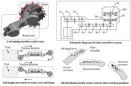
Figure 1.
Schematic diagram of the shearer ranging arm movement, gear set, and lubricating oil level.
The torque generated by the rocker arm’s cutting motor is transmitted to the cutting drum through a multi-stage spur gear transmission system, enabling coal seam extraction. The spur gear reduction mechanism not only provides speed reduction but also extends the rocker arm’s length to meet cutting height requirements. Meanwhile, the two-stage planetary gear system, featuring a high reduction ratio, primarily performs speed reduction and torque amplification functions.
The cutting motor incorporates a slender and flexible torque shaft that is directly connected to the Z1 shaft assembly. The Z1, Z2, Z4, Z5, and Z6 shaft assemblies function as idler gear sets, while the Z3-1 and Z3-2 assemblies collectively form the central gear cluster. The Z7 gear serves as a critical transmission component, efficiently delivering power to the cutting drum. The Z1 to Z3 shaft assemblies, located closer to the motor, operate at higher rotational speeds and constitute the high-speed spur gear stage of the shearer’s rocker arm. Due to speed reduction effects, the Z4 to Z7 assemblies operate at lower speeds, primarily ensuring transmission stability and reliability as the low-speed spur gear stage. These components achieve speed reduction and torque amplification through gear meshing. The Z6 and Z7 gear sets, being closest to the drum, play particularly crucial roles in power transmission. Critical gear parameters are given in Table 1.

Table 1.
Rocker arm transmission gear basic parameter table.
Table 1 summarizes the basic parameters of the rocker arm transmission gears. In the table, “Gear NO.” corresponds to the gear identifier (Z1–Z9), “Shaft” indicates the associated transmission shaft number or stage (e.g., I, II, III), and “Module” and “Teeth” represent the gear module and the number of teeth, respectively. For a detailed reference, please refer to the corresponding labels in Figure 1.
During a single transverse cutting pass, the rocker arm performs coal cutting at a specific tilt angle. Under gravitational effects, the lubricating oil within the rocker arm’s gear transmission system cannot achieve uniform distribution to fully cover all gears. When the pass is completed and reverse cutting begins, the rocker arm executes a full circumferential movement to reorient itself for the next cutting cycle. Throughout this motion, gravity continues to hinder complete oil coverage across all gear components.
2.1.2. 3D Model and Mesh Generation
This study employs a 1:1 scale model of an actual shearer rocker arm, as illustrated in Figure 2. Given the structural complexity of the complete rocker arm’s assembly and the primary focus on the meshing characteristics of gears Z6 and Z7, the model has been appropriately simplified to reduce computational demands. Non-critical components with negligible influence on the research objectives were removed, retaining only essential structural elements relevant to the investigation.
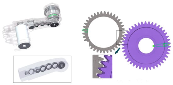
Figure 2.
Rocker arm gear set and grid of two meshing gears.
For this simulation, HyperMesh 2025 software was employed for structural meshing. Given the symmetric nature of the gears, to streamline the meshing process, a single tooth segment was isolated for initial mesh generation. The complete gear mesh was then achieved through rotational patterning and array operations. The 3D gear mesh model is shown in Figure 2. Following mesh generation, rigorous quality checks were performed to ensure compliance with specified requirements for element size, angular distortion, and other critical parameters. A mesh convergence study was performed by testing four mesh densities: 62 k, 235 k, 366 k, and 1258 k elements. The results showed that beyond 300 k elements, the maximum stress variation in key regions (Z6/Z7 tooth roots) was less than 3%, indicating convergence. Given computational efficiency and accuracy, we retained the 366 k-element mesh for subsequent analyses. The final gear mesh consisted of 366,000 elements and 416,000 nodes. The simulation was conducted using ANSYS commercial software, with the higher-order hexahedral element Solid186 selected as the most suitable choice due to the strong nonlinearities and fluid–structure interaction effects involved in this analysis. Mesh distortion under high thermal gradients was controlled through adaptive remeshing. In transient thermo-mechanical simulations, adaptive refinement was applied to regions with thermal gradients exceeding 50 C/mm, dynamically increasing element density to maintain element quality. For fluid–thermal–solid coupling, smoothing algorithms were used to adjust element shapes during gear rotation, preventing excessive distortion in oil interface regions.
Gear shafts were supported by cylindrical roller bearings, constraining translational degrees of freedom while allowing rotational freedom. Housing connections were modeled via rigid constraints at bearing seats, consistent with the rocker arm cast-iron housing stiffness. Gear rotation was simulated using prescribed angular velocities for Z6/Z7, with torque derived from the cutting resistance moment to ensure dynamic consistency. This approach balances computational efficiency with realistic rotational behavior.
2.2. Material Properties and Load Conditions
2.2.1. Material Properties
The simulation covers the flow field, temperature field, and stress field, requiring the setting of structural and fluid material parameters in the computational domain based on actual material properties. The material selected for the shearer rocker arm transmission gears is 18Cr2Ni4WA. The material parameters include Young’s modulus, Poisson’s ratio, and SN/EN curves. The rocker arm lubricating oil uses N320 material, which has good temperature resistance and can maintain appropriate viscosity under high-temperature conditions. The lubricant material parameters include density, viscosity, thermal conductivity, and specific heat capacity. The specific material parameters are shown in Table 2 and Table 3.

Table 2.
Material parameters of the gear.

Table 3.
Oil material parameters.
2.2.2. Load Conditions
During the operation of a shearer, the load borne by the cutting drum exhibits multi-dimensional dynamic distribution characteristics. To establish the mechanical model of the drum shaft system, the cutting resistance can be equivalently transformed into loads along the drum axis. The equivalent resistance can be decomposed into a normal force component passing through the drum shaft center and a tangential resistance moment component rotating about the axis.
The normal force component is transmitted to the rocker arm housing through the static equilibrium system of the front and rear support bearings of the planetary carrier, forming a key load input for the housing structure. Meanwhile, the tangential resistance moment is transferred to the final reduction gear pair through the idler shaft assembly of the planetary gear system, constituting the dynamic torque load on the low-speed transmission gears.
Based on the fluctuation characteristics of drum loads, a model of fluctuating drum loads is constructed using the static mean value and transient fluctuation value of the loads:
where R0 represents the mean value of the drum load; Kd denotes the load fluctuation coefficient; Tzr indicates the rated value of the cutting resistance moment; Tz0 stands for the mean value of the cutting resistance moment; and
represents the normalized load fluctuation curve, with a value range of [−1, 1].
The primary load studied in this gear transmission system is the cutting resistance moment. The cutting drum is connected to the low-speed zone Z7 gear through a planetary gear set and idler shaft. Because the idler shaft in the shearer’s rocker arm is a fixed component, the random loads generated during coal wall cutting are transmitted through the idler shaft to affect the Z7 gear. That is,
where M is the cutting resistance moment, N·m; i is the transmission ratio from the rocker arm idler shaft to the drum; and T is the resistant torque on Z7 gear, N·m.
The rocker arm’s Z6 and Z7 gears are subjected to multiple excitation loads, including dry friction in air, oil lubrication cooling, and variable cutting loads, resulting in extremely complex loading characteristics. Therefore, this study focuses on investigating the temperature field, stress field characteristics, and fatigue life prediction of the Z6 and Z7 gears under such complex working conditions, aiming to provide references for subsequent structural optimization of the rocker arm and cooling system design. A constant friction coefficient was employed throughout the analysis. The effects of thermal softening on the material properties of the gear steel were not explicitly incorporated into the current model. Gear–tooth contact was modeled as surface to surface contact, which combines penalty stiffness for contact enforcement with friction. In addition, material properties were treated as temperature-independent, focusing primarily on the integrated methodology and procedure.
2.3. Simulation Approaches
2.3.1. Transient Thermo-Mechanical Coupling for Dry Friction
This study first examines the gear dry friction condition. A gear thermal–mechanical coupling analysis method is adopted. The method calculates material elastic deformation to solve computational non-convergence caused by large mesh deformation. By introducing both transient and steady-state temperature fields, a thermal–mechanical coupling model is established to study temperature variations in gear transmission and their potential effects on mechanical performance. This calculation will simulate two complete gear rotation cycles. Because data from the first cycle may be unstable due to initial condition effects, only data from the second cycle are retained for extraction and analysis to ensure results’ accuracy and reliability. To capture detailed states of each tooth during meshing, such as stress variations, a small time step is set.
Transient analysis of gears Z6 and Z7 was conducted in the Coupled Field Transient module. By setting different rotational speeds and random loads, the dynamic response of the gears during actual operation was obtained. The calculated heat flux data in Excel format were converted to CSV and input as External Data into the Steady-State Thermal module for further solution.
In the Steady-State Thermal module, the working state of gears under oil-free lubrication cooling conditions was simulated. A thorough analysis was performed on the dry friction temperature fields and temperature variation patterns of both gears at different speeds. The temperature distribution analysis under dry friction conditions further reveals the characteristics of gear dry friction. These analysis results provide boundary conditions for subsequent calculations of thermal–fluid–structure coupling fields and life prediction optimization. Figure 3 shows the overall temperature field distribution of gears Z6 and Z7 at different rotational speeds.
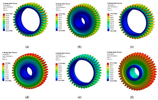
Figure 3.
Temperature field distribution of Z6 and Z7 gears at 700–900 r/min. (a) Z6 700 r/min; (b) Z7 700 r/min; (c) Z6 800 r/min; (d) Z7 800 r/min; (e) Z6 900 r/min; (f) Z7 900 r/min.
2.3.2. Fluid–Thermal–Solid Coupling for Wet Lubrication
Section 2.3.1 conducted thermo-mechanical coupling analysis of Z6 and Z7 gears under dry friction conditions without lubrication at the rocker arm’s +45 deg position. The temperature field distribution and thermally induced stress variations of both gears at different rotational speeds were obtained. This subsection employs ANSYS-Fluent, combining the standard two-phase flow turbulence model and convective heat transfer characteristics to establish a thermal–fluid–structure coupled analysis model for the gears. The analysis examines the flow field characteristics, temperature field features, and thermal stress distributions of Z6 and Z7 gears during the rocker arm’s movement from +45 deg to −45 deg at various rotational speeds, as well as the temperature field and thermal stress characteristics of Z6 and Z7 gears under fully lubricated conditions when the rocker arm reaches −45 deg. The research results provide boundary conditions for subsequent gear life prediction.
The thermal–fluid–structure coupling simulation essentially realizes the transfer between heat flux in the physical field and the flow field. The flow field calculates key near-wall parameters, including velocity and pressure, to derive the near-wall convective heat transfer coefficient, which is then fed back to the physical field. The physical field comprehensively considers both heat flux and the convective heat transfer coefficient to compute the near-wall temperature and transmits the temperature information back to the flow field. This forms a bidirectional synchronous coupled calculation process that ensures thermodynamic and hydrodynamic interactions.
Fluid domains used hexahedral-dominant meshes with 2.2M elements. Gear surfaces included 5-layer inflation layers (first layer thickness = 0.05 mm) to resolve boundary layers. A standard two equation model was used for its accuracy in near-wall heat transfer, with y+ values maintained between 30 and 100. Heat flux between fluid and structural domains was transferred via node-based interpolation, with a tolerance of 1 × 10⁻⁵ W/m2 to ensure continuity. The fluid domain was enclosed (no inlet/outlet), with oil volume fraction tracked via VOF; moving walls (gear surfaces) were assigned angular velocities matching structural simulations.
Under the condition that the rotational speed of Z6 gear ranges from 700 to 900 r/min, three different oil immersion depths were additionally set to analyze the temperature field variations of both Z6 and Z7 gears at different speeds. These three oil level heights were set at 25%, 50%, and 75% of the complete immersion depth of Z6/Z7 gears under rocker arm swinging conditions. The current simulation simulated gear rotation through moving walls, thereby calculating the convective heat transfer coefficient to achieve coupling between thermal and flow fields. The temperature field data obtained from the thermal–flow coupling solution were imported into the Static Structural module as boundary conditions for thermal stress analysis, obtaining the thermal stress distribution characteristics of the gear system under lubrication conditions. When the gear speed was 700 r/min, it could be observed that a small amount of lubricating oil was carried to the non-immersed surface through gear rotation, and, as the oil level increased, the gears gradually became immersed in the lubricating oil. The distribution of lubricating oil is shown in Figure 4.

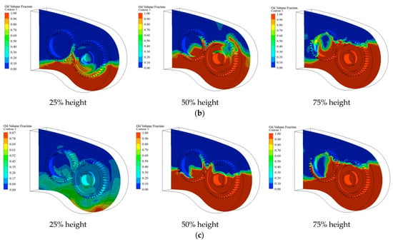
Figure 4.
Z6 gear oil distribution. (a) 700 r/min; (b) 800 r/min; (c) 900 r/min.
2.3.3. Fatigue Life Prediction Method
Section 2.3.1 and Section 2.3.2 described the thermal–fluid–structure coupling analysis of the Z6 and Z7 gears under the rocker arm’s ±45 deg operating conditions and during its movement from +45 deg to −45 deg, obtaining the temperature field distributions and thermally induced stress variations of both gears at different rotational speeds and oil immersion depths. These results provide data support for the fatigue life analysis of the two gears in this section. This section will combine the ANSYS nCode fatigue analysis tool to perform fatigue life analysis of both gears after comprehensive consideration of multiple factors.
As shown in Figure 5, the material’s S-N curve is crucial for evaluating component fatigue performance. In ANSYS nCode, the S-N curve can be fitted based on the material type and tensile strength values, which can also meet the requirements of fatigue analysis. The figure below shows a typical S-N curve generated in nCode, which adopts a multi-segment linear fitting method.
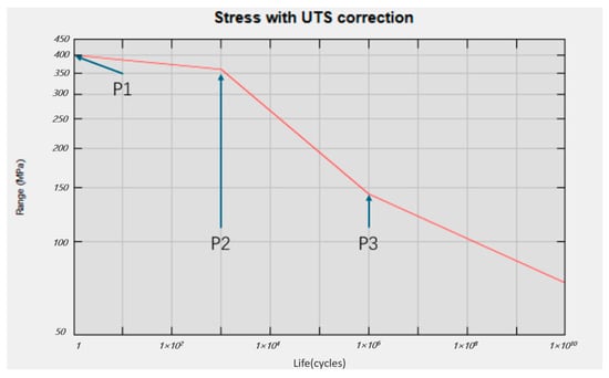
Figure 5.
S-N curve generated in nCode.
In actual operating conditions, the material’s loading process involves complex stress variations, making it insufficient to rely solely on S-N curves for comprehensive life assessment. To more accurately reflect the material’s fatigue performance, the concept of mean stress correction is introduced. This section employs nCode DesignLife software 2025.1 to conduct fatigue life simulation analysis of Z6 and Z7 gears, investigating the critical locations and fatigue life cycles of these gears during the rocker arm’s operational transition from +45 deg to −45 deg. Previous sections have completed the simulation analysis of temperature fields and stress variations for Z6 and Z7 gears, and ANSYS nCode can directly read these analysis results. In nCode DesignLife, load settings are configured through time steps, and standard stress cycle damage calculations are selected. The stress combination method employs the Absolute Principal Stress approach, while the Goodman curve correction method is applied with the survival rate set at 50%.
In nCode DesignLife, the Fatigue Result Display module provides intuitive contour plots for analyzing the fatigue damage and fatigue life of the Z6 and Z7 gears in the large-mining-height shearer. Without considering the influence of external cooling conditions, both the bulk temperature and stress values of the rocker arm gears in the large-mining-height shearer remain at relatively high levels. The fatigue life calculation employs cyclic loading based on temperature and stress conditions under both dry friction and fully immersed lubrication scenarios. Figure 6 and Figure 7 show the fatigue damage and fatigue life conditions of the two gears without considering cooling effects.


Figure 6.
Fatigue damage diagram of Z6/Z7 gears without considering cooling. (a) Z6 700 r/min; (b) Z6 800 r/min; (c) Z6 900 r/min.
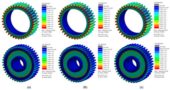
Figure 7.
Fatigue life diagram of Z6/Z7 gears without considering cooling. (a) Z6 700 r/min; (b) Z6 800 r/min; (c) Z6 900 r/min.
3. Key Insights for Optimization
3.1. Analysis of Thermal Stress Fields
3.1.1. Analysis of Dry Friction Temperature Field and Stress Field in Gears
At a rotational speed of 700 r/min, observation of the overall temperature contour plots for Z6 and Z7 gears reveals that the highest temperature points for both gears are located in the meshing region of the gear teeth. The temperature gradually decreases from the addendum circle and the dedendum circle to the gear inner diameter. For the Z6 gear, the maximum temperature point occurs at the junction between the gear end face, the addendum circle, and the tooth surface, reaching Tmax = 594 deg. For the Z7 gear, the maximum temperature point is located at the intersection of the tooth surface and the gear end face, with Tmax = 295 deg.
When the speed increases to 800 r/min, the highest temperature points of both gears remain in the meshing region of the gear teeth. The temperature distribution pattern from the addendum circle and the dedendum circle to the inner diameter persists. The Z6 gear’s maximum temperature point remains at the junction of the gear end face, the addendum circle, and the tooth surface, now reaching Tmax = 746 deg. The Z7 gear’s peak temperature occurs at the addendum circle and the tooth surface interface, measuring Tmax = 332 deg. At 900 r/min, the maximum temperature points of both gears continue to be located in the tooth meshing area, maintaining the same radial temperature gradient. The Z6 gear’s peak temperature reaches Tmax = 871 deg at the interface between the gear end face and the tooth surface. Figure 8 shows the maximum temperature variation curves of Z6 and Z7 gears under dry friction conditions at different speeds. The plot clearly demonstrates a linear growth trend in maximum gear temperatures with increasing rotational speed. The Z7 gear consistently maintains lower temperatures than the Z6 gear, attributable to its larger volume, lower rotational speed, and consequently more effective convective heat transfer that facilitates better heat dissipation.
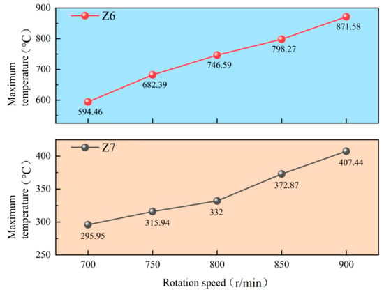
Figure 8.
Maximum temperature of Z6 and Z7 gears with different speeds of dry friction.
Taking the meshing condition at 800 r/min as an example, Figure 9 shows the stress distribution contour plots of Z6/Z7 gears. The plots clearly demonstrate significant stress concentration in the contact region. However, due to frictional effects, the maximum stress values during meshing do not occur at the contact point but are instead biased toward the dedendum area of each gear. Furthermore, the Z6 gear exhibits higher stress values than the Z7 gear. Figure 10 presents the dry friction meshing stress results at 900 r/min rotational speed. During the simulation process, because the Z6 gear rotates directly at the rated speed while the Z7 gear starts from rest, the transient stresses during initial rotation are extremely high. This calculation covers stress conditions during two complete gear rotation cycles. Data from the first cycle were discarded, with analysis focused primarily on the second cycle’s data.
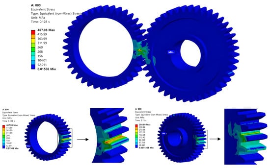
Figure 9.
Z6/Z7 gear meshing thermal stress distribution.
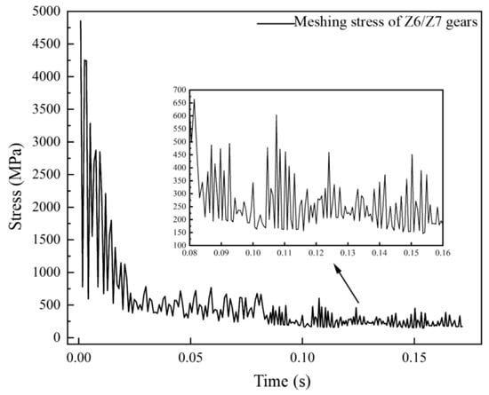
Figure 10.
Meshing stress of 900 r/min Z6 and Z7 gears.
Figure 11 presents the maximum thermo-mechanical stress variation curves of Z6/Z7 gears under dry friction conditions at different rotational speeds, demonstrating a clear positive correlation between rotational speed and thermal stress levels. As the speed progressively increases from 700 r/min to 900 r/min, both gears exhibit significant thermal stress escalation, with the Z6 gear’s maximum thermal stress rising from 519.49 MPa to 803.86 MPa (representing a 54.8% increase), while the Z7 gear’s maximum thermal stress increases from 227.14 MPa to 352.68 MPa (a 55.3% increase), revealing that the Z6 gear consistently sustains approximately 2.3 times higher thermal stress than its Z7 counterpart across all tested speed conditions, with both gears displaying near-linear stress growth patterns that underscore the substantial thermal–mechanical coupling effects under high-speed dry friction operation.
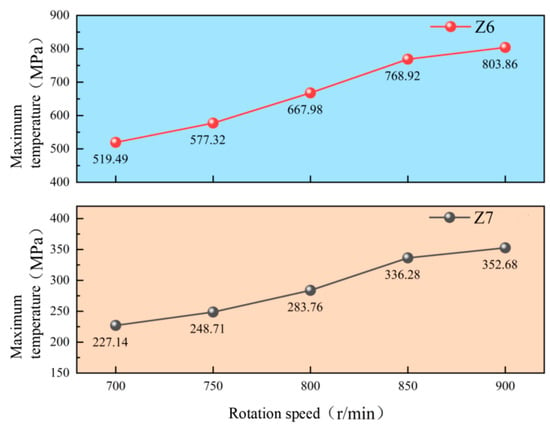
Figure 11.
Maximum stress of Z6/Z7 gears under different speeds of dry friction.
3.1.2. Temperature Field and Thermal Stress Analysis of Gear Under Different Oil Immersion Depth
At 700 r/min rotational speed, observations reveal a progressive improvement in convective heat transfer characteristics with increasing oil immersion levels. The distribution of lubricating oil is illustrated in Figure 4, while Figure 12 presents the convective heat transfer coefficient contours on gear surfaces. Key findings demonstrate that when immersion depth reaches 25%, the completely air-exposed Z6 gear shows minimal heat transfer with a maximum coefficient (hmax = 74.9 W/(m2·K)) concentrated in the meshing zone, whereas the partially immersed Z7 gear achieves significantly enhanced cooling (hmax = 3690 W/(m2·K)). At 50% immersion, the Z6 gear’s heat transfer coefficient dramatically increases (hmax = 8880 W/(m2·K)) with partial lubrication, while the mostly submerged Z7 gear reaches peak performance (hmax = 11,300 W/(m2·K)) at the meshing interface. Further immersion to 75% results in more uniform heat distribution, with maximum coefficients shifting to tooth surfaces and addendum circles (Z6: hmax = 6400 W/(m2·K); Z7: hmax = 5210 W/(m2·K)), demonstrating that optimal heat transfer occurs at intermediate immersion levels where both splash lubrication and submerged effects are present.
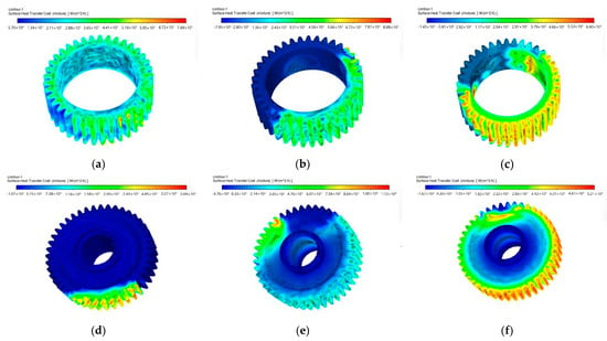
Figure 12.
Convection heat transfer coefficient of Z6/Z7 gears at 700 r/min. (a) Z6 25% height; (b) Z6 50% height; (c) Z6 75% height; (d) Z7 25% height; (e) Z7 50% height; (f) Z7 75% height.
Figure 13 displays the convective heat transfer coefficient distribution on Z6 and Z7 gear surfaces at 800 r/min. Key observations reveal that increased rotational speed enhances lubrication effects even at low immersion levels; at 25% immersion, while Z6 remains largely unsubmerged, the higher speed causes oil splashing that improves its heat transfer, compared to Z7’s partial immersion performance. When immersion reaches 50%, both gears show significant improvement. At 75% immersion, the combined effects of direct immersion and splash lubrication from the increased speed create more uniform heat transfer distribution on Z6, while substantially enhancing cooling on its unsubmerged portions.


Figure 13.
Convection heat transfer coefficient of Z6/Z7 gears at 800 r/min. (a) Z6 25% height; (b) Z6 50% height; (c) Z6 75% height; (d) Z7 25% height; (e) Z7 50% height; (f) Z7 75% height.
Figure 14 presents the convective heat transfer coefficient distribution of Z6/Z7 gears at 900 r/min, demonstrating enhanced lubrication effects from higher rotational speeds. At 25% immersion, the Z6 gear, while technically unsubmerged, achieves substantial oil coverage through vigorous splashing (hmax = 1870 W/(m2·K) in meshing zone), with the Z7 gear showing even better performance (hmax = 2470 W/(m2·K)) due to combined immersion and splash effects. The 50% immersion condition yields remarkable heat transfer improvement, while 75% immersion provides more uniform cooling distribution on Z6’s partially submerged surfaces, with splash lubrication significantly enhancing heat transfer on unsubmerged areas. These results clearly illustrate how increased rotational speed amplifies both splash lubrication effects and overall thermal performance across all immersion levels.
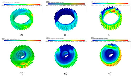
Figure 14.
Convection heat transfer coefficient of Z6/Z7 gears at 900 r/min. (a) Z6 25% height; (b) Z6 50% height; (c) Z6 75% height; (d) Z7 25% height; (e) Z7 50% height; (f) Z7 75% height.
The cooling effectiveness varies significantly with oil immersion depth, directly influencing temperature and thermal stress distributions. At 25% immersion depth, where Z6 remains unsubmerged while Z7 is partially immersed, Figure 15 demonstrates how rotational speed affects thermal performance; at 700 r/min, uniform temperature distribution on Z6 (Tmax = 551 deg) contrasts with Z7’s cooler immersed portions (Tmax = 287 deg), both peaking at meshing zones. Increasing the speed to 800 r/min expands cooled regions, lowering peak temperatures. The 900 r/min condition shows continued but decelerating cooling, revealing a nonlinear speed–temperature relationship. Corresponding thermal stress distributions (see Figure 16) exhibit complex interdependencies among speed, temperature, and immersion conditions, with stress concentrations consistently located in meshing areas despite varying cooling patterns.
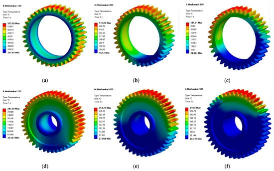
Figure 15.
Temperature distribution of two gears at 25% immersion depth at different speeds. (a) Z6 700 r/min; (b) Z6 800 r/min; (c) Z6 900 r/min; (d) Z7 700 r/min; (e) Z7 800 r/min; (f) Z7 900 r/min.


Figure 16.
Thermal stress distribution of two gears at 25% oil immersion depth at different speeds. (a) Z6 700 r/min; (b) Z6 800 r/min; (c) Z6 900 r/min; (d) Z7 700 r/min; (e) Z7 800 r/min; (f) Z7 900 r/min.
The analysis reveals a direct correlation between thermal stress and temperature distributions across both gears. As rotational speed increases from 700 r/min to 900 r/min, corresponding temperature reductions lead to proportional decreases in thermal stress; the Z6 gear’s maximum thermal stress declines from 510.33 MPa to 444.9 MPa (a 12.8% reduction), while the Z7 gear shows a more significant stress reduction from 345.61 MPa to 282.09 MPa (a 18.4% decrease), demonstrating that higher rotational speeds under 25% oil immersion conditions effectively mitigate thermal stresses despite the mechanical loading increase, with the Z7 gear exhibiting greater stress sensitivity to cooling effects than its Z6 counterpart.
The temperature distribution of the two gears at 75% oil immersion depth under different rotational speeds is shown in Figure 17. When the immersion depth is 75%, gear Z6 is half-submerged in lubricating oil, while a small portion of gear Z7 is exposed to the air. As the rotational speed increases, the lubricating oil is carried to the surfaces of the non-immersed parts. At a speed of 700 r/min, the overall temperature contour reveals that as the oil immersion depth increases, the high-temperature region of gear Z6 significantly shrinks. The submerged portion of the gear exhibits a uniform temperature distribution, while in the non-submerged portion the temperature is highest at locations farthest from the oil’s surface and gradually decreases along the direction of the lubricating oil. For gear Z7, the submerged part shows lower and more uniform temperatures, whereas the exposed part exhibits higher temperatures. The highest temperature points for both gears are located at the meshing positions of the gear teeth. The maximum temperature of gear Z6 is 479 deg, while that of gear Z7 is 200.31 deg.


Figure 17.
Gear temperature distribution at 75% oil immersion depth from 700 to 900 r/min. (a) Z6 700 r/min; (b) Z6 800 r/min; (c) Z6 900 r/min; (d) Z7 700 r/min; (e) Z7 800 r/min; (f) Z7 900 r/min.
Figure 18 shows the temperature variation curves of the Z6/Z7 gear pair under different rotational speeds and oil immersion depths. From the figure, it can be observed that under constant speed conditions, the temperature of gear Z6 decreases as the oil immersion depth increases. During the transition from no oil to half oil, as well as from half oil to full oil, the temperature gradient changes significantly. The temperature variation trend of gear Z7 is more complex than that of Z6. When the rotational speed is below 800 r/min, its temperature decreases with increasing oil immersion depth. However, when the speed exceeds 800 r/min, the temperature first decreases, then increases, and finally decreases again as the immersion depth increases. Under fixed oil immersion conditions, the temperature trends of the two gears also exhibit significant differences. In the absence of lubrication, the temperatures of both Z6 and Z7 gears increase with rising rotational speed. Under half oil lubrication, the temperatures of both gears decrease as the speed increases, which is attributed to the dominant cooling effect of the lubricating oil film at moderate immersion depths. Under full oil lubrication, the temperature first decreases and then increases with increasing speed, reaching its lowest value in the 700–800 r/min range. Beyond this range, the temperature rises again due to increased churning losses (churning losses refer to viscous dissipation energy due to oil agitation).
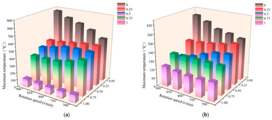
Figure 18.
Temperature variation of two gears at different speeds and immersion depths. (a) Gear Z6; (b) gear Z7.
Figure 19 illustrates the thermal stress variation of the Z6/Z7 gear pair under different rotational speeds and oil immersion depths. As shown in the figure, the trend of thermal stress aligns closely with the temperature changes described earlier. Under constant speed conditions, when the rotational speed of gear Z7 is below 800 r/min, its thermal stress initially increases and then decreases with increasing oil immersion depth. However, when the speed exceeds 800 r/min, the thermal stress first decreases, then increases, and finally decreases again as the immersion depth rises. This complex stress behavior can be attributed to the coupled effects of multiple factors. In the lower speed range, as the oil immersion depth increases, the cooling effect of the lubricating oil film gradually strengthens. At the same time, intensified oil agitation inside of the gearbox leads to localized stress concentrations. In the higher speed range, in addition to the thermal–fluid–structure interaction effects, additional stresses arise from the dynamic pressure effects of the oil film.
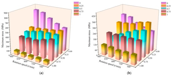
Figure 19.
Thermal stress variation of two gears at different speeds and immersed oil depths. (a) Gear Z6; (b) gear Z7.
3.2. Fatigue Life Prediction and Discussion
The simulated life data without considering cooling were compiled and summarized, with the results shown in Figure 20 and Figure 21. From the figures, it can be observed that in the absence of external cooling, the rotational speed and gear fatigue life exhibit a negative correlation. As the speed increases, the fatigue life of the gears decreases. The fatigue life of the Z6 gear follows a concave downward trend; while higher speeds reduce fatigue life, the diminishing effect gradually weakens. This is because at higher speeds, the influence of temperature on gear life becomes more pronounced, thereby mitigating the impact of stress on fatigue life. In contrast, the fatigue life of the Z7 gear exhibits a concave downward trend, where increasing speed not only reduces fatigue life but also intensifies the effect. This occurs because higher speeds lead to more frequent and complex load fluctuations during drum coal cutting, accelerating gear wear. In this simulation, one cycle was defined as a single rotation of the Z6 gear. Assuming the coal shearer operates 18 h per day, the predicted service life of the Z6 and Z7 gears under uncooled conditions was converted, as detailed in Table 4.
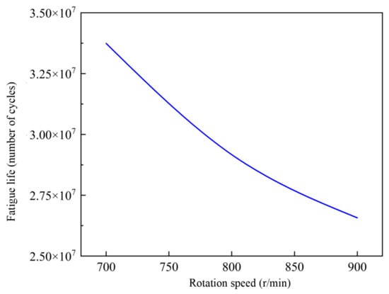
Figure 20.
Fatigue life curve of Z6 without cooling.
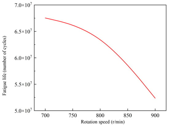
Figure 21.
Fatigue life curve of Z7 without cooling.

Table 4.
Fatigue life table of Z6/Z7 gears without cooling.
The life simulation data considering cooling were compiled into curves, as shown in Figure 22 and Figure 23. Based on the analysis of these figures, under external cooling conditions, the negative correlation between rotational speed and gear fatigue life persists. As the rotational speed increases, the fatigue life of the gears gradually shortens. For the Z6 gear, the fatigue life continues to exhibit a concave downward trend. While increasing speed reduces fatigue life, the extent of this effect gradually diminishes. In contrast, the Z7 gear still shows a concave downward trend in fatigue life; higher speeds lead to a more pronounced reduction in fatigue life over time. By comparing the fatigue life trends of the Z6 and Z7 gears under varying speeds, significant differences between the two become evident. These findings provide important guidance for selecting appropriate gear materials and optimizing working conditions in practical applications, ultimately enhancing the overall reliability and durability of mechanical systems. In this simulation, one cycle was defined as a single rotation of the Z6 gear. Assuming the coal shearer operates 18 h per day, the predicted service life of the Z6 and Z7 gears under cooling conditions was converted, as detailed in Table 5.
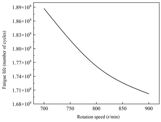
Figure 22.
Fatigue life curve of Z6 with cooling.
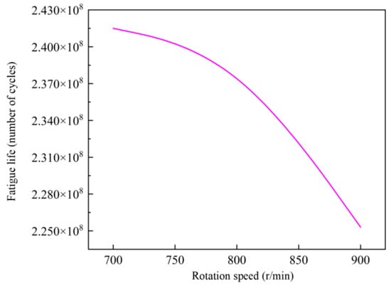
Figure 23.
Fatigue life curve of Z7 with cooling.

Table 5.
Fatigue life table of Z6/Z7 gears with cooling considered.
4. Discussion of Optimization Strategies
Cooling System Structural Optimization
The conventional rocker arm design primarily relies on a water jacket in the rocker arm housing for cooling, where the cooling water carries away most of the heat. However, with the substantial increase in rocker arm power and the demand for continuous operation in high-yield, high-efficiency working conditions, the heat generated by transmission efficiency losses can no longer be effectively managed through traditional methods. To address this, the rocker arm requires a dedicated thermal balancing system. Based on an analysis of heat sources and dissipation under various operating conditions, the optimization involves redesigning the housing water jacket, installing cooling pipes within the gear chamber, implementing a gear pump hydraulic system for forced lubrication and enhanced cooling, and integrating temperature sensors to trigger alarms when temperatures exceed predefined thresholds.
Based on thermal–fluid coupling simulations revealing optimal convective heat transfer coefficients at 50% oil immersion depth (Z6: 8880 W/m2·K; Z7: 11,300 W/m2·K), a staged cooling solution is proposed. Two sets of φ25 mm spiral copper tubes (50 mm spacing) are installed inside of the gearbox, with high-pressure coolant (3.5 L/min flow rate) first directed to form jet cooling at Z6 gear root stress concentration zones (corresponding to the 803 MPa high-stress region in Figure 11) and then circulating through the planetary head’s high-temperature housing channel. The low-pressure circuit employs serpentine flow paths covering the entire housing surface, with wall thickness optimized to 8 mm for enhanced thermal conductivity. This design reduces the Z6 gear’s peak temperature from 871 °C (dry friction) to 479 °C (75% oil immersion) at 900 rpm while achieving a 44% thermal stress reduction (from 803 MPa to 444 MPa).
5. Conclusions
This research establishes a coupled multiphysics approach to diagnose and resolve fatigue failure in shearer rocker arm gears Z6 and Z7. Key findings demonstrate that dry friction at ±45° tilt induces severe temperature and stress concentrations in gear meshing zones, with Z6 experiencing 2.3× higher stress than Z7 due to rotational speed and geometric factors. Lubrication depth critically governs cooling efficiency, where 50% oil immersion maximizes heat transfer through combined splash–submersion effects, while shallow 25% immersion amplifies thermal gradients. Fatigue life analysis confirms that uncooled operation shortens gears’ lifespan exponentially with increasing speed, reducing Z6’s service life from 44.6 days at 700 rpm to 27.3 days at 900 rpm, with thermal stress identified as the primary damage driver, and Z6 was consistently outperformed by Z7 due to higher stress magnitudes. Proposed optimizations include a redesigned cooling system implementing staged jet-spiral cooling that reduces Z6’s peak temperature from 871 °C to 479 °C and stress by 44% at 900 rpm, alongside an intelligent lubrication system featuring dual-gear pumps with thermal feedback that triples oil-carrying efficiency, extends Z7’s life to 277 days at 800 rpm, and eliminates dry friction through dynamic oil control. Validation confirms that these strategies collectively extend gear life over 200% while reducing peak stress by 40–55%. Future work will pursue parametric gear topology optimization and real-time thermal management systems for adaptive lubrication control.
Intelligent Lubrication System Enhancement
When the rocker arm operates at steep angles, the upper-position gears and bearings lose lubrication access, causing rapid deterioration of gear meshing conditions and a sharp increase in heat generation. To address these operational challenges and enhance the service life of gears/bearings while improving overall system reliability, a forced lubrication cooling system was specifically designed for the rocker arm gearbox. This system utilizes the gearbox oil as its working fluid, incorporating a helical pump installed at either the high-speed or low-speed end of the shearer’s rocker arm shaft assembly. Driven by the corresponding gear, the pump’s rotating action centrifugally propels oil through internal passages to the opposite end of the rocker arm, ensuring proper lubrication and cooling for the upper-position components. This maintains optimal lubrication conditions for the upper gears and bearings, reducing friction, minimizing temperature rise, and, ultimately, extending component lifespan.
To solve the uneven oil film distribution problem under steep-angle conditions (where Z6 exhibits a 264 °C temperature differential at 25% immersion), a dual-gear pump forced lubrication system (displacement: 12 mL/rev) was developed. A helical pump mounted on the high-speed shaft works with a centrifugal oil distributor to achieve dynamic oil supply (0.25–0.4 MPa pressure), integrated with embedded PT100 sensors (±0.5 °C accuracy) to implement a three-stage thermal control strategy. When Z6’s tooth surface temperature exceeds 120 °C, pump speed increases by 20%; temperatures beyond 150 °C activate auxiliary cooling, and those above 180 °C trigger power reduction protection. Simulations demonstrate that this solution extends the Z7 gear’s life from 75 to 277 days at 800 rpm (Table 4 and Table 5) while tripling oil-carrying efficiency (the non-immersed zone heat transfer coefficient improves from 74.9 to 1870 W/m2·K at 700 rpm).
Author Contributions
Conceptualization, Y.T. and X.D.; methodology, Q.Z.; software, C.S.; validation, X.S., J.Z. and Q.Z.; formal analysis, C.S.; investigation, W.X.; resources, Q.Z.; data curation, J.Z.; writing—original draft preparation, C.S.; writing—review and editing, X.D.; visualization, J.Z.; supervision, Y.T.; project administration, X.D.; funding acquisition, Q.Z. All authors have read and agreed to the published version of the manuscript.
Funding
This research was funded by National Natural Science Foundation of China grant number 52574194. This research project is also funded by the Open Project of the National Engineering Laboratory for Coal Mining Machinery.
Data Availability Statement
The original contributions presented in the study are included in the article, further inquiries can be directed to the corresponding authors.
Conflicts of Interest
Authors Chunxiang Shi, Xiangkun Song, and Weipeng Xu were employed by the company China Coal Technology & Engineering Group Shanghai Co., Ltd. The remaining authors declare that the research was conducted in the absence of any commercial or financial relationships that could be construed as a potential conflict of interest.
References
- Cao, X.; Xu, W.; Zhao, J.; Dusn, Y.; Yang, X. Research on large language model for coal mine equipment maintenance based on multi-source text. Appl. Sci. 2024, 14, 2946. [Google Scholar] [CrossRef]
- Kang, H.; Gao, F.; Xu, G.; Ren, H. Mechanical behaviors of coal measures and ground control technologies for China’s deep coal mines–A review. J. Rock Mech. Geotech. Eng. 2023, 15, 37–65. [Google Scholar] [CrossRef]
- Zhang, C.; Bai, Q.; Han, P. A review of water rock interaction in underground coal mining: Problems and analysis. Bull. Eng. Geol. Environ. 2023, 82, 157. [Google Scholar] [CrossRef]
- Jin, X.; Han, D.; Zhao, G.; Zhao, L.; Wang, Y.; Yang, S. Dynamic Response and Failure Analysis of Shearer Rocker arm Housing Under Nonlinear Impact Loads. J. Vib. Eng. Technol. 2025, 13, 1–21. [Google Scholar] [CrossRef]
- Wan, L.; Wang, J.; Ma, D.; Zeng, Q. Thermo-mechanical coupling characteristics of the shearer’s guiding shoe during the friction. Sci. Rep. 2024, 14, 24825. [Google Scholar] [CrossRef] [PubMed]
- Leszek, G.; Krzysztof, P.; Daniel, P.; Edward, K.; Katarzyna, A.; Konrad, G.; Paweł, I. Influence of Contamination of Gear Oils in Relation to Time of Operation on Their Lubricity. Appl. Sci. 2021, 11, 11835. [Google Scholar] [CrossRef]
- Figlus, T.; Kozioł, M.; Kuczyński, Ł. Impact of Application of Selected Composite Materials on the Weight and Vibroactivity of the Upper Gearbox Housing. Materials 2019, 12, 2517. [Google Scholar] [CrossRef] [PubMed]
- Park, Y.; Hong, G.; Jun, S.; Choi, J.; Kim, T.; Kang, M.; Jang, G. Thermo-Fluid–Structural Coupled Analysis of a Mechanical Seal in Extended Loss of AC Power of a Reactor Coolant Pump. Lubricants 2024, 12, 212. [Google Scholar] [CrossRef]
- Yazdani, M.; Soteriou, M.C. A novel approach for modeling the multiscale thermo-fluids of geared systems. Int. J. Heat Mass Transf. 2014, 72, 517–530. [Google Scholar] [CrossRef]
- Yazdani, M.; Soteriou, M.C.; Sun, F.; Chaudhry, Z. Prediction of the thermo-fluids of gearbox systems. Int. J. Heat Mass Transf. 2015, 81, 337–346. [Google Scholar] [CrossRef]
- Yazdani, M.; Soteriou, M.; Botros, B.; Wu, H. A novel approach to model thermo-fluids of gearbox systems. In Proceedings of the Heat Transfer Summer Conference, Minneapolis, MN, USA, 14–19 July 2013; American Society of Mechanical Engineers: New York, NY, USA, 2013; Volume 55485, p. V002T04A011. [Google Scholar]
- Liu, W.; Fu, H.; Chen, Y. A novel method for gear reducer’s transient temperature field analysis based on thermo-fluid interaction. In Proceedings of the 2015 3rd International Conference on Machinery, Materials and Information Technology Applications, Qingdao, China, 28–29 November 2015; Atlantis Press: Dordrecht, The Netherlands, 2015; pp. 1702–1711. [Google Scholar]
- Fatourehchi, E.; Shahmohamadi, H.; Mohammadpour, M.; Rahmani, R.; Theodossiades, S.; Rahnejat, H. Thermal analysis of an oil jet-dry sump transmission gear under mixed-elastohydrodynamic conditions. J. Tribol. 2018, 140, 051502. [Google Scholar] [CrossRef]
- Hong, K.; Wang, C.; Xu, F. Finite-element thermal analysis of flows on moving domains with application to modeling of a hydraulic arresting gear. J. Therm. Anal. Calorim. 2021, 144, 963–972. [Google Scholar] [CrossRef]
- Zheng, G.; Xu, P.; Li, L. Investigate on the fluid dynamics and heat transfer behavior in an automobile gearbox based on the LBM-LES model. Lubricants 2025, 13, 117. [Google Scholar] [CrossRef]
- Maccioni, L.; Pagliari, L.; Concli, F. CFD Insights into Gear Jet Lubrication: Exploring Objectives, Challenges, and Methodologies Through a Literature Review. In Proceedings of the International Symposium on Industrial Engineering and Automation, Bolzano, Italy, 19–21 June 2024; Springer Nature Switzerland: Cham, Switzerland, 2024; pp. 34–47. [Google Scholar]
- Qasemian, A.; Moradi, F.; Karamati, A.; Keshavarz, A.; Shakeri, A. Hydraulic and thermal analysis of automatic transmission fluid in the presence of nano-particles and twisted tape: An experimental and numerical study. J. Cent. South Univ. 2021, 28, 3404–3417. [Google Scholar] [CrossRef]
- Wszelaczyński, G.; Capanidis, D.; Paszkowski, M.; Leśniewsk, T. Operating Problems of Lubrication of Friction Nodes in Mining Machines Working in an Aggressive Environment. In Proceedings of the International Scientific-Technical Conference on Hydraulic and Pneumatic Drives and Control, Staniszow, Poland, 21–23 October 2020; Springer International Publishing: Cham, Switzerland, 2020; pp. 228–238. [Google Scholar]
- Shi, C.; Song, X.; Xu, W.; Tian, Y.; Yang, L.; Dong, X.; Zhang, Q. SPH Simulation of Gear Meshing with Lubricating Fluid–Solid Coupling and Heat-Transfer Process. Processes 2025, 13, 730. [Google Scholar] [CrossRef]
- Savari, A. Crack assessment in spiral-welded pipelines repaired by composite patch: A SMART and failure assessment diagram approach. J. Pipeline Sci. Eng. 2024, 5, 100222. [Google Scholar] [CrossRef]
- Liu, X.B.; Li, G.; Wang, Y.L.; Zeng, K.H.; Yang, W.M.; Wang, F.Y. Advances in intelligent identification of fiber-optic vibration signals in oil and gas pipelines. J. Pipeline Sci. Eng. 2024, 4, 100184. [Google Scholar] [CrossRef]
- Chen, F.; Zhang, M.; Qian, J.; Fei, Y.; Chen, L.; Jin, Z. Thermo-mechanical stress and fatigue damage analysis on multi-stage high pressure reducing valve. Ann. Nucl. Energy 2017, 110, 753–767. [Google Scholar] [CrossRef]
- Cao, X.; Duan, Y.; Wang, G.; Zhao, J.; Ren, H.; Zhao, F.; Yang, X.; Zhang, X.; Fan, H.; Xue, X.; et al. Research review on life-cycle health management and intelligent maintenance of coal mining equipment. J. China Coal Soc. 2025, 50, 694–714. [Google Scholar]
- Yin, Y.; Grondin, G.Y.; Obaia, K.H.; Elwi, A.E. Fatigue life prediction of heavy mining equipment. Part 1: Fatigue load assessment and crack growth rate tests. J. Constr. Steel Res. 2007, 63, 1494–1505. [Google Scholar] [CrossRef]
- Butlewski, M.; Dahlke, G.; Drzewiecka, M.; Pacholski, L. Fatigue of miners as a key factor in the work safety system. Procedia Manuf. 2015, 3, 4732–4739. [Google Scholar] [CrossRef]
Disclaimer/Publisher’s Note: The statements, opinions and data contained in all publications are solely those of the individual author(s) and contributor(s) and not of MDPI and/or the editor(s). MDPI and/or the editor(s) disclaim responsibility for any injury to people or property resulting from any ideas, methods, instructions or products referred to in the content. |
© 2025 by the authors. Licensee MDPI, Basel, Switzerland. This article is an open access article distributed under the terms and conditions of the Creative Commons Attribution (CC BY) license (https://creativecommons.org/licenses/by/4.0/).