Abstract
Proofs of Retrievability (PoR) is one of the basic functions of electronic evidence preservation center in cloud. This paper proposes two PoR schemes to execute the workflow of evidence preservation center, which are named Finer Grained Proofs of Retrievability (FG-PoR) and More Lightweight Proofs of Retrievability (ML-PoR). The two PoR schemes do not use multi-replication technology or erasure code technology, but employ the verification tags and signatures to implement provable data possession and data recovery dual functions. When some data blocks have been lost in Archive Storage Area (ASA), FG-PoR can recover each data block of evidence matrix, but ML-PoR can only recover a column of evidence matrix. The analysis results show our two PoR schemes do not only provide the integrity verification guarantee but also have robust recovery guarantee to electronic evidence in cloud. The two schemes can allow for lower computation and storage costs than other similar schemes; moreover, ML-PoR can provide lower costs than FG-PoR.
1. Introduction
In a general operating environment, electronic evidence is derived from systematic data and network data. Systematic data include system logs, audit records, temporary or hidden files, hard disk drive exchange partition, etc. Network data include logs of firewall, Intrusion Detection Systme (IDS), and router, E-mail information, real-time chats, network monitoring records, etc. Electronic evidence may provide massive information and resource bases in various forms. In cloud computing environments, it provides users with flexible services in a transparent manner. One fundamental aspect of service is that data is being centralized or outsourced into a “cloud”, which is a collection of devices and resources connected through the Internet. Electronic evidence is a special kind of data, and it must be integrated before it is sent to a court of law. When it is being collected from the cloud, it should be fixed in a specific form and stored safely on the local or cloud server so as to prevent them from being destructed by nature and man. This operating process is called electronic evidence preservation [1].
Cloud forensics is a cross discipline of cloud computing and electronic forensics. Cloud computing is a shared collection of configurable networked resources (e.g., networks, servers, storage, applications and services) that can be reconfigured quickly with minimal effort [2]. Electronic forensics is the application of computer science principles to recover electronic evidence for presentation in a court of law [3]. Cloud forensic investigations are likely to involve evidence acquisition, preservation and analysis in a cloud. From the investigators’ perspective, storing electronic evidence remotely in a cloud in a flexible, on demand manner brings appealing benefits: relief of the burden of storage management, access to data with independent geographical locations, and avoiding capital expenditure on hardware, software and personnel maintenance [4]. Also, it can reduce the litigants to the objectivity of the evidence, simplify the review procedure of evidence in court, and effectively assess the fairness and justice in the administration.
While cloud computing makes these advantages more appealing than ever, it also brings new and challenging security threats to the outsourced electronic evidence. On one hand, electronic evidence has its own vulnerability, such that it can more easily be deleted, forged, altered and removed than traditional printed evidence. On the other hand, cloud computing is open and has a virtual operation environment for all users. When the outsourced electronic evidence is stored to a cloud, it might be unclear as to where evidence is processed within the cloud, and such processing might occur in different jurisdictions. Once electronic evidence is extracted from the cloud and is sent to the court, it must be true, reliable and integrated, in accord with legal requirements [5]. So how to ensure the integrity of electronic evidence in cloud is a considerable challenge to both cloud service providers and research institutes.
2. Related Work
When the users send their data to the Cloud Storage Server (CSS), they should pay a fee to obtain an appropriate storage space to preserve their data. The CSS is not fully trusted because the storage devices are under the control of the Cloud Service Provides (CSP), not the users. The importance of ensuring the integrity of data in untrusted storage servers has been highlighted by some researchers, and they have proposed two basic schemes to check the availability and integrity of cloud storage data. The two basic schemes are called provable data possession (PDP) [6] and proofs of retrievability (PoR) [7]. A PDP scheme can only verify the integrity of a file on the server, but cannot ensure the retrievability of a file [8]. However, a PoR scheme is a challenge response protocol. In the protocol, the server can demonstrate to the client that a file is intact and retrievable without any loss and corruption.
The provable data possession (PDP) scheme was built upon by Ateniese et al. [6]. In the scheme, the user could utilize RSA-based homomorphic tags to challenge the server. The server proved possession of the file by sending back a few randomly sampled blocks of the file. In a subsequent study, Curtmola et al. [9] described a multiple replica PDP (MR-PDP) scheme, which ensured that multiple replicas of the user’s files were stored at the untrusted storage server. Barsoum [10] constructed two efficient multi-copy PDP (EMC-PDP) protocols which were called Deterministic EMC-PDP (DEMC-PDP) and Probabilistic EMC-PDP (PEMC-PDP). PEMC-PDP depended on spot checking by validating a random subset of the file blocks instead of validating all the blocks in DEMC-PDP to reduce computation and storage overhead.
The proofs of retrievability (PoR) scheme was first proposed by Juels et al. [7], and this scheme used spot-checking and error-correcting codes to ensure both “possession” and “retrievability” of the files on remote servers. Shacham and Waters [11] also proposed a PoR scheme. In this scheme, the file was encoded using erasure code and was split into some blocks. The server used homomorphic algorithm to compact all data tags into a short tag, and it was taken as the response to the client. Bowers et al. [8] introduced a retrievable scheme for cloud storage data, which permitted a set of servers to prove to a client that a stored file was intact and retrievable. In [2], Cong Wang et al. utilized the homomorphic token to ensure the integrity of erasure-coded data with additional feature of data error localization. In a subsequent work, Qian Wang et al. [12] allowed a third party auditor to verify the integrity of the data stored in cloud based on Merkle hash tree.
To cloud forensics, several works have already been published in this field. Wolthusen [13] noted that when attempting to locate evidence in a distributed and complex environment such as the cloud, the distributed and virtual nature of the cloud would likely increase the difficulty of evidence collection, making tracing activity and re-construction of evidence more challenging. Grispos et al. [14] analyzed how established digital forensic procedures would be invalidated and discussed several new research challenges in the cloud environment. Birk and Wegener [15] assessed whether it was possible for the customer of cloud computing services to perform a traditional digital investigation from a technical point of view. Furthermore, they discussed possible solutions and possible new methodologies helping customers to perform such investigations.
In above works, literature [6,12] were the PDP schemes. They could only check the integrity of the file through the server sending back random samples of the file. Literature [2,7,8,11] were all the PoR schemes based on erasure codes. They used erasure codes technology to compact many data blocks into fewer redundancy. This approach added storage costs of redundant data and computation costs of encoding and decoding. Literature [9,10] were the PoR schemes based on multiple replica. In the two schemes, each data object needed to be created some copies, and the size of data objects and their copies were the same. Unfortunately, the storage costs of the copies in the two schemes was too high. Literature [13,14] discussed the potential benefits and challenges of cloud computing for electronic forensic investigations. Literature [15] mentioned possible solutions and methodologies of technology to face the challenges. But these three papers [13,14,15] did not all provide technical detail on how to solve the problem. This paper proposes two verification schemes of retrievability for preservation of electronic evidence in cloud computing environment. The two schemes are kept light-weight by employing verification tags and signatures with neither the use of erasure codes nor the use of mutiple-replica.
3. An Electronic Evidence Preservation Center in Cloud
Due to outdated equipment and the lack of technical support, it is impossible that electronic evidence could be preserved perfectly by the courts or the public security organs. This means electronic evidence will usually be stored in a special preservation center. In general, a traditional electronic evidence preservation center uses some technologies, such as encryption algorithm, digital signature, time stamp and digital digest to ensure the security of electronic evidence [1]. In a cloud computing environment, except for these conventional technologies, privacy protection, PDP and PoR technologies should be considered in a preservation center. This paper designs two PoR schemes for application in a cloud preservation center for electronic evidence. The architecture of the electronic evidence preservation center is shown in Figure 1.
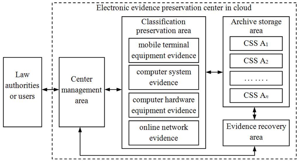
Figure 1.
The architecture of electronic evidence preservation center in cloud.
Figure 1.
The architecture of electronic evidence preservation center in cloud.

From Figure 1, the preservation center contains multiple functional areas: Center Management Area (CMA), Classification Preservation Area (CPA), Archive Storage Area (ASA), Evidence Recovery Area (ERA). When Law Authorities or Users (LAU) send electronic evidence to the preservation center, they only interact with the CMA, so it will greatly improve the work efficiency.
3.1. Center Management Area (CMA)
In the electronic evidence preservation center, electronic evidence would be stored using a classification storage method by the CPA. Each evidence file is divided into fixed-size chunks, and ASA will store these chunks. Each chunk will be assigned a label at the time of creation. The CMA stores all metadata associated with classification evidence. Also, the CMA provides the services of electronic evidence reception, notary and forensic services for the law authorities and users (LAU), which is an external service window of the electronic evidence preservation center. Moreover, it executes business process supervision and coordination and management to other function areas. It will be taken as a Trusted Audit Center (TAC) in our PoR schemes.
3.2. Classification Preservation Area (CPA)
If the CMA has received electronic evidence from the LAU, it will forward the evidence to CPA to store temporarily. When electronic evidence has been collected from selected mobile devices, including mobile phones, MP3/4, PDA, etc., it will be recorded as mobile terminal equipment evidence to be preserved. When electronic evidence is extracted from computer systematic data, including a system log, audit records, temporary files, exchange files, or hidden files, it will be recorded as computer system evidence to be preserved. When electronic evidence has been collected from all kinds of private computers, notebook computers, storage servers, or the hard drives of this equipment, it will be collected as hardware equipment evidence to be preserved. Electronic evidence may be attained from network servers and hosts, such as webpage browsing historical records, cookies, favorites, cache information, etc. It may also be attained from network communication data including logs of firewalls, IDS, routers, Email information, real-time chat and network monitoring records, etc. This evidence will be recorded as online network evidence to be preserved. After electronic evidence has been classified over a long time span in the CPA, it will be divided into chunks to be sent to the ASA. The CPA will store the metadata of all chunks, such as the tables, mapping the labels to chunk locations.
3.3. Archive Storage Area (ASA)
In this area, there are some Chunk Storage Servers (CSS)  in the cloud. These servers will store all chunks of the evidence file, and each chunk is split into some blocks. In FG-PoR schemes, each block has a corresponding tag, and all blocks and tags will be stored in the ASA. The ASA will provide safe, reliable, efficient storage services for massive electronic evidence in the cloud. When the CMA asks the CPA about the integrity of a stored evidence file, the CPA will query the metadata for the locations of the desired chunks and construct proofs of retrievability to prove that the file is intact and retrievable.
in the cloud. These servers will store all chunks of the evidence file, and each chunk is split into some blocks. In FG-PoR schemes, each block has a corresponding tag, and all blocks and tags will be stored in the ASA. The ASA will provide safe, reliable, efficient storage services for massive electronic evidence in the cloud. When the CMA asks the CPA about the integrity of a stored evidence file, the CPA will query the metadata for the locations of the desired chunks and construct proofs of retrievability to prove that the file is intact and retrievable.3.4. Evidence Recovery Area (ERA)
When the LAU needs their electronic evidence, it sends a request message to the CMA. The CMA accesses the chunks of evidence file by querying the CPA for the locations of the desired chunks; if the chunks are not being operated on, the CPA replies with the locations, and the CMA then contacts the ERA. The ERA retrieves the evidence from CSS  , and uses hash function to check the integrity of the evidence file. Then it sends the evidence to the CMA, and further forwards it to the LAU. The CMA could also check the integrity of the evidence file by running verifying algorithm VeriResp( ). If the ERA or the CMA has found some error data blocks of the evidence matrix, the ERA will use the retrieved algorithm RetrData( ) to recover these data blocks.
, and uses hash function to check the integrity of the evidence file. Then it sends the evidence to the CMA, and further forwards it to the LAU. The CMA could also check the integrity of the evidence file by running verifying algorithm VeriResp( ). If the ERA or the CMA has found some error data blocks of the evidence matrix, the ERA will use the retrieved algorithm RetrData( ) to recover these data blocks.4. Proofs of Retrievability for Electronic Evidence
From Figure 1, we know that CPA, ERA and CMA will coordinate to ensure the integrity and retrievability of electronic evidence. Moreover, the CMA will play the role of Trusted Audit Center (TAC) in collaboration. The workflow of LAU, CPA, ASA, ERA and CMA as the five functional areas is shown in Figure 2.
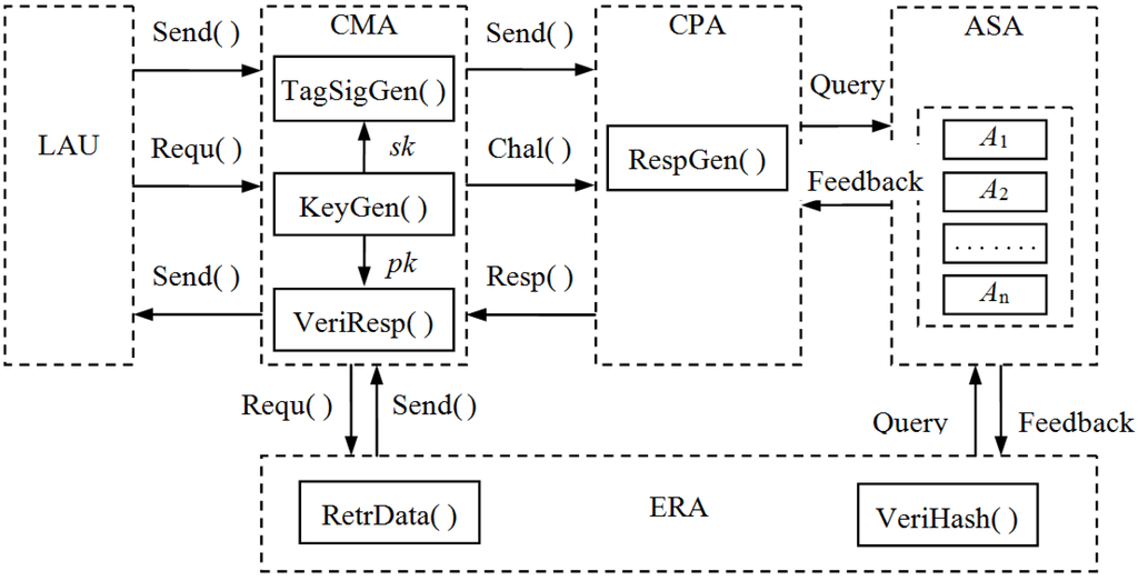
Figure 2.
The workflow of five functional areas. “Send( )” means that the sender sends the evidence file to the receiver; “Requ( )” means that the sender sends the request message to the receiver; “Chal( )” means that one side sends the challenge message to the other side; “Resp( )” means that one side sends the response values to the other side; “Query” means that the CPA or the ERA queries chunks of the ASA; “Feedback” means that the ASA gives feedback messages of chunks and blocks.
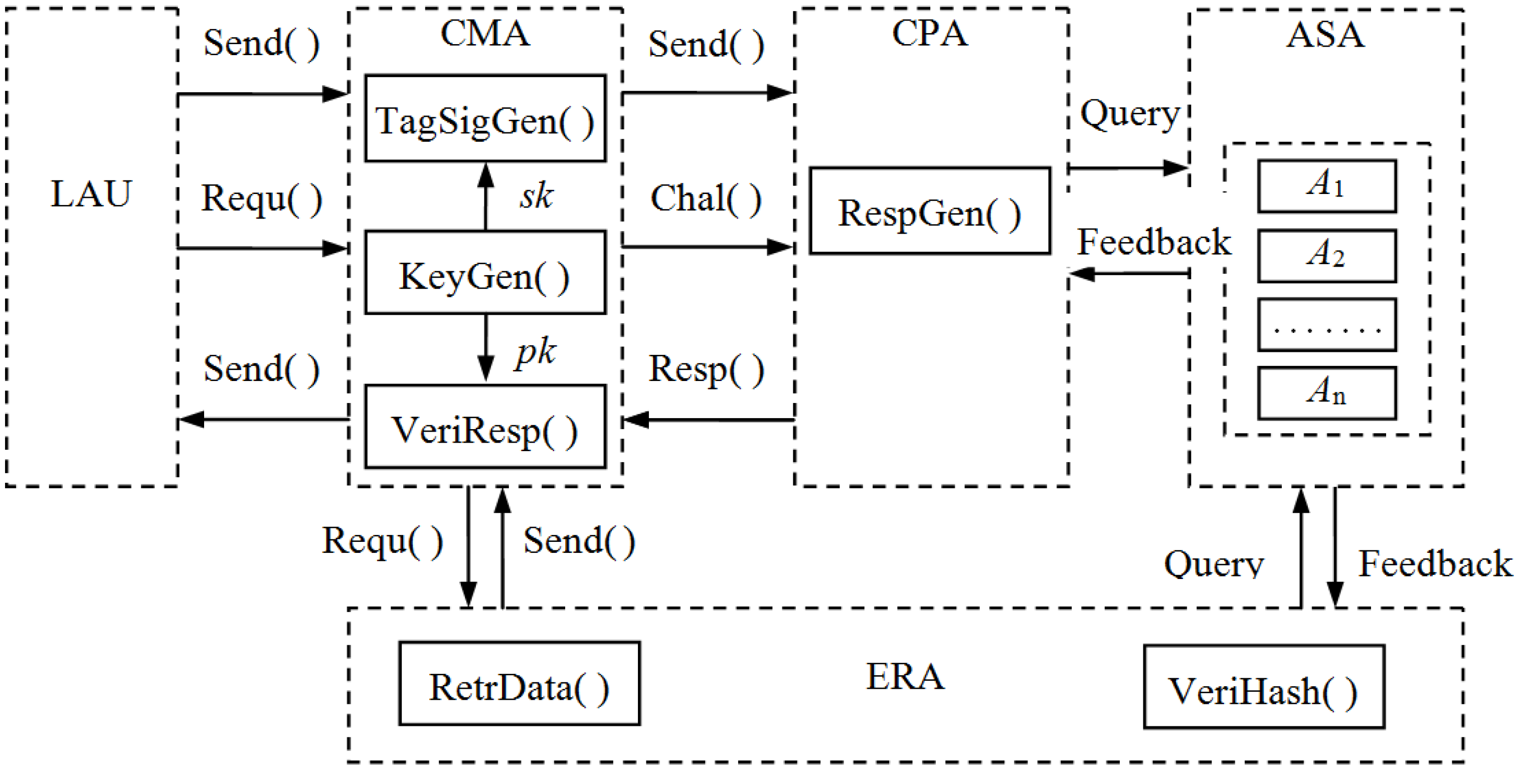
In our work, we provide two PoR schemes: Finer Grained Proofs of Retrievability (FG-PoR) and More Lightweight Proofs of Retrievability (ML-PoR) to execute the workflow of the electronic evidence preservation center. There are six algorithms in the three functional areas of CPA, ERA and CMA. The CMA has three algorithms TagSigGen( ), KeyGen( ), and VeriResp( ); the CPA has an algorithm RespGen( ); the ERA has two algorithms RetrData( ) and VeriHash( ). These six algorithms will be described in Section 4.1. It is assumed the LAU has an evidence file  and will send it to the ASA to store. The CMA will send challenge message Chal( ) to the CPA so as to make regular checks on the integrity and availability of electronic evidence at appropriate intervals. The CPA will query the metadata for the locations of the challenged chunks and compute response values to send back to the CMA. When the CMA has found out some data blocks are incorrect, it will tell the information to the ERA, then the ERA uses retrieved algorithm RetrData( ) to recover electronic evidence. When all incorrect data blocks have been recovered, the ERA will send them back to the ASA again.
and will send it to the ASA to store. The CMA will send challenge message Chal( ) to the CPA so as to make regular checks on the integrity and availability of electronic evidence at appropriate intervals. The CPA will query the metadata for the locations of the challenged chunks and compute response values to send back to the CMA. When the CMA has found out some data blocks are incorrect, it will tell the information to the ERA, then the ERA uses retrieved algorithm RetrData( ) to recover electronic evidence. When all incorrect data blocks have been recovered, the ERA will send them back to the ASA again.4.1. Notation and Preliminaries
Let be an electronic evidence file: it is divided into  chunks, and each chunk is split into
  blocks:
  , where each block
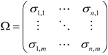
  . These evidence blocks may be expressed in the following matrix form
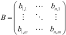
be an electronic evidence file: it is divided into chunks, and each chunk is split into blocks: , where each block . These evidence blocks may be expressed in the following matrix form
In execution processes of the workflow of five functional areas, our two schemes FG-PoR and ML-PoR both consist of six algorithms. We start with the precise definition of FG-PoR scheme and ML-PoR scheme.
Definition 1. FG-PoR scheme and ML-PoR scheme are both collection of six polynomial-time algorithms (KeyGen, TagSigGen, RespGen, VeriResp, VeriHash, RetrData) such that:
 KeyGen( ). This algorithm is run by the CMA to generate public key
  and private key
  .
. TagSigGen
  . This algorithm is run by the CMA. It takes as input the private key
  and the evidence blocks set , and outputs the tags set
  and signatures set
  .
. RespGen
  . This algorithm is run by the CPA. It takes as input the evidence blocks subset
  and the tags subset
  , and returns a response value
  as output. It will query the ASA whether the ASA is actually storing all evidence blocks intact or not.
 VeriResp
  . This algorithm is run by the CMA. It takes as input the public key
  , the response value and signatures subset
  , It will output 1 if the integrity of all evidence blocks is verified, otherwise will output 0. VeriHash(H,H′). This algorithm is run by the ERA. It takes as input two sets of hash values of evidence blocks
  and H′. is saved previously, and H′ is computed when it is needed. If and H′ are equal, outputs 1, otherwise outputs 0.
 RetrData(Ω′, S′). This algorithm is run by the ERA. It takes as input the set of tags Ω′ and the set of signatures S′ of the error evidence blocks returned from the ASA, and outputs the correct evidence blocks
  .
.4.2. Nyberg-Rueppel Signature Scheme
The Nyberg-Rueppel signature scheme first appeared in the literature in [16], named after its authors K. Nyberg and R.A. Rueppel. Its security is based on the intractability of discrete logarithm problem. Camenisch et al. [17] described this scheme as follows:
The parameters consist of a prime  , a prime factor
  of
of  , and an element
  of order . The signer’s private key is a random element
  , while the corresponding public key is
  .
.
, a prime factor of , and an element of order . The signer’s private key is a random element , while the corresponding public key is .To sign a message  , the signer selects
  at random and computes
  and
and  as follows:


, the signer selects at random and computes and as follows:
The pair  is the signature of the message
  . The signer sends the message
  and the signatures
  to the receiver.
is the signature of the message . The signer sends the message and the signatures to the receiver.When the receiver has received and the signatures , to verify the validity of a signature, it checks that the following equality holds:

and the signatures , to verify the validity of a signature, it checks that the following equality holds:
If the equation is true, then the signature is valid. Otherwise, the signature is invalid.
4.3. Finer Grained Proofs of Retrievability (FG-PoR)
We propose two schemes, Finer Grained Proofs of Retrievability (FG-PoR) and More Lightweight Proofs of Retrievability (ML-PoR), which are both based on the Nyberg-Rueppel signature scheme. The execution processes of FG-PoR consist of the following six steps. Before describing the execution processes, we first give a definition for FG-PoR scheme.
Definition 2. A FG-PoR scheme built on the six algorithms (KeyGen, TagSigGen, RespGen, VeriResp, VeriHash, RetrData) can guarantee data possession. Also, it can recover each data block of all chunks of the evidence file.
4.3.1. Key Generation
The CMA runs the KeyGen( ) algorithm to generate key pair  . Chooses two primes
  and , is a factor of , and an element of order . Chooses a secret random element
  , and sets
  . Chooses a secret key
  ,
,  is the length of the key
  . Thus the secret key is
  and the public key is
  .
.
. Chooses two primes and , is a factor of , and an element of order . Chooses a secret random element , and sets . Chooses a secret key , is the length of the key . Thus the secret key is and the public key is .4.3.2. Tags and Signatures Generation
Given evidence blocks  , the CMA runs the TagSigGen( ) algorithm to create a tag
  and a signature
  for each block
  as
as
 where
where 

 ,
,  is a pseudo-random function. The tags set may be expressed in the following matrix form
, the CMA runs the TagSigGen( ) algorithm to create a tag and a signature for each block as
, is a pseudo-random function. The tags set may be expressed in the following matrix form
The CMA sends the set of evidence blocks  and the set of corresponded tags
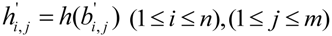
  to the CPA; the CPA categorizes the chunks and sends all blocks to the ASA, and only saves metadata of the chunks on it. Then the CMA computes
 and sends hash values set
  to the ERA. Finally, the CMA deletes all copies of , and . It preserves only signatures set
  and metadata of the evidence file on its own storage. The storage distribution of the electronic evidence blocks and their tags on the CSS of the ASA is given in Figure 3.
and the set of corresponded tags to the CPA; the CPA categorizes the chunks and sends all blocks to the ASA, and only saves metadata of the chunks on it. Then the CMA computes and sends hash values set to the ERA. Finally, the CMA deletes all copies of , and . It preserves only signatures set and metadata of the evidence file on its own storage. The storage distribution of the electronic evidence blocks and their tags on the CSS of the ASA is given in Figure 3.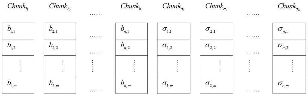
Figure 3.
The storage distribution of evidence blocks and tags on the Chunk Storage Servers (CSS) in Finer Grained Proofs of Retrievability (FG-PoR).
Figure 3.
The storage distribution of evidence blocks and tags on the Chunk Storage Servers (CSS) in Finer Grained Proofs of Retrievability (FG-PoR).
4.3.3. Challenge Choice
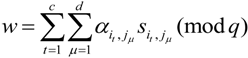
After the CMA has sent challenge values to the CPA, and the CPA has given back response values to the CMA, the CMA will check the integrity of all evidence blocks by the response values. The challenge values are  , where
  is the identity number of the evidence file , and it may be expressed as
  .
.  is the number of challenged columns of the evidence matrix,
  .
.  is the number of challenged rows of the evidence matrix,
  .
.  are three fresh keys and are chosen randomly for each challenge.
, where is the identity number of the evidence file , and it may be expressed as . is the number of challenged columns of the evidence matrix, . is the number of challenged rows of the evidence matrix, . are three fresh keys and are chosen randomly for each challenge. Let be a pseudo-random function,  be a pseudo-random permutation. At each challenge, both the CMA and the CPA use key
  to generate indices of challenged columns
 , also use key
  to generate indices of challenged rows
 . They further use key
  to derive
  coefficients
  ,
,  ,
,  .
.
be a pseudo-random function, be a pseudo-random permutation. At each challenge, both the CMA and the CPA use key to generate indices of challenged columns , also use key to generate indices of challenged rows . They further use key to derive coefficients , , .4.3.4. Response Generation
The CPA runs the RespGen( ) to generate response values to prove that the ASA is still preserve all evidence blocks intact. The ASA has held evidence blocks  and corresponded tags in Section 4.3.2. Grounded on indices of challenged columns and rows
  ,
,  , the CPA chooses subset of evidence blocks
  and subset of tags
  from the ASA by querying the metadata of evidence chunks, then it generates response values
  based on
  and
and  .
.
and corresponded tags in Section 4.3.2. Grounded on indices of challenged columns and rows , , the CPA chooses subset of evidence blocks and subset of tags from the ASA by querying the metadata of evidence chunks, then it generates response values based on and .The subset of evidence blocks  and the subset of tags may be expressed in the following matrix form
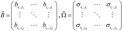
and the subset of tags may be expressed in the following matrix form
The computational processes of response values are as follows

are as follows
The CPA takes response values  as a proof that the ASA possesses electronic evidence , finally the CPA sends
  to the CMA.
as a proof that the ASA possesses electronic evidence , finally the CPA sends to the CMA.4.3.5. Response Verification
After the CMA has received response values  from the CPA, it takes out indices of challenged columns , challenged rows
  , and coefficients
  . Then the CMA chooses the subset of signatures
  from the set of signatures
  which has been saved previously. Further, the CMA computes
from the CPA, it takes out indices of challenged columns , challenged rows , and coefficients . Then the CMA chooses the subset of signatures from the set of signatures which has been saved previously. Further, the CMA computes
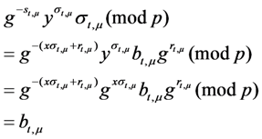
Now it runs verify algorithm VeriResp( ) to check the following equation
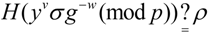
If the above equation is true, the verify algorithm returns 1, the CMA believes that the ASA preserves well evidence blocks set . Otherwise, the verify algorithm returns 0.
. Otherwise, the verify algorithm returns 0.The above equation holds because:
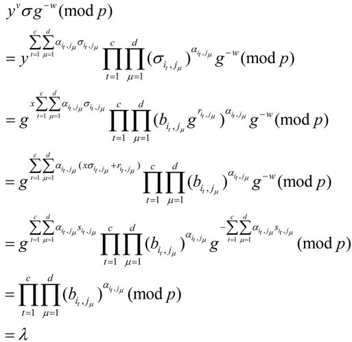
Further

4.3.6. Evidence Retrieve
At a later time, the LAU needs its evidence file , it sends a request message Requ  to the CMA. The CMA will forward message Requ to the CPA and the ERA. The ERA queries the chunks and the blocks of the evidence file from the ASA. After the ERA has got feedback message
  , it will use hash function to compute the hash value of each element of evidence matrix
  to get the set
  . Each element of the set
  is calculated as following
, it sends a request message Requ to the CMA. The CMA will forward message Requ to the CPA and the ERA. The ERA queries the chunks and the blocks of the evidence file from the ASA. After the ERA has got feedback message , it will use hash function to compute the hash value of each element of evidence matrix to get the set . Each element of the set is calculated as following
The ERA runs VeriHash( ) algorithm to compare the set of hash values  with
with  , which has been saved in Section 4.3.2. If
  , then
  , it means that all evidence blocks are intact. If one or several hash values of the set are not equal, then this means that these evidence blocks may have been altered in network transmitting or on the ASA storage. In Section 4.3.5, when the verify algorithm returns 0, it shows also that some evidence blocks may be incorrect in the ASA.
with , which has been saved in Section 4.3.2. If , then , it means that all evidence blocks are intact. If one or several hash values of the set are not equal, then this means that these evidence blocks may have been altered in network transmitting or on the ASA storage. In Section 4.3.5, when the verify algorithm returns 0, it shows also that some evidence blocks may be incorrect in the ASA.Assume checked out evidence block  , in order to get original evidence block
  , the ERA queries its tag
  from the ASA, and asks the CMA to send back corresponding signature
  . As long as tag and are not damaged, the ERA will use RetrData( ) algorithm to recover evidence block

, in order to get original evidence block , the ERA queries its tag from the ASA, and asks the CMA to send back corresponding signature . As long as tag and are not damaged, the ERA will use RetrData( ) algorithm to recover evidence block
In fact
4.4. More Lightweight Proofs of Retrievability (ML-PoR)
We modify FG-PoR scheme to attain a More Lightweight Proofs of Retrievability (ML-PoR) scheme. It consists of the following six steps, but it has a weaker recovery guarantee than FG-PoR. We give a definition for ML-PoR scheme that is described as follows.
Definition 3. A ML-PoR scheme built on the six algorithms (KeyGen, TagSigGen, RespGen, VeriResp, VeriHash, RetrData) can guarantee data possession, and it can recover each chunk of the evidence file.
4.4.1. Key Generation
Key generation is the same as FG-PoR, and the secret key is  and the public key is
  .
.
and the public key is .4.4.2. Tags and Signatures Generation
Let  be a pseudo-random function, the CMA uses secret key
  to derive random sequence
be a pseudo-random function, the CMA uses secret key to derive random sequence
Given the evidence blocks  , the CMA computes

, the CMA computes
The CMA runs the TagSigGen( ) algorithm to create a tag and a signature for each  as
as

as
Further, the CMA computes hash value for each column of evidence matrix as

as
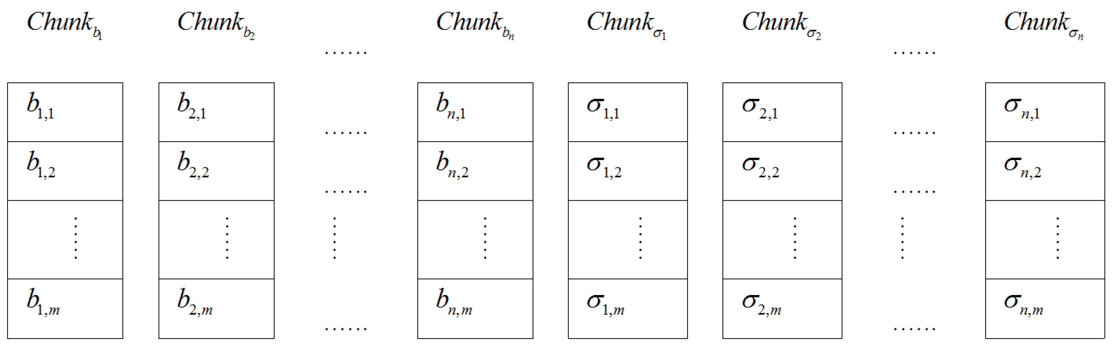
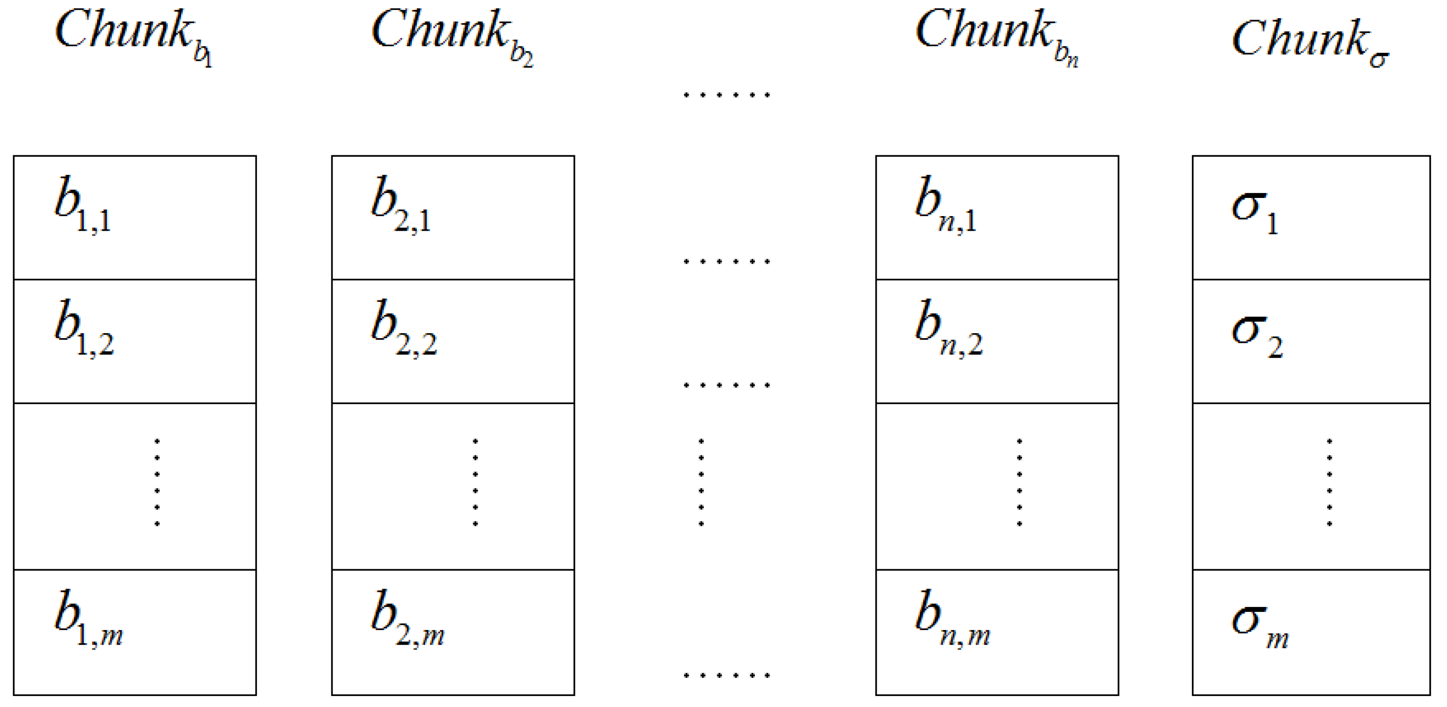
Here, the storage distribution of the electronic evidence blocks and their tags on the CSS of the ASA is shown in Figure 4.
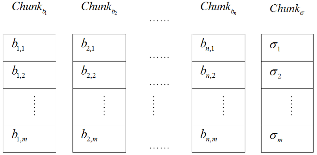
Figure 4.
The storage distribution of evidence blocks and tags on the Chunk Storage Servers(CSS) in More Lightweight Proofs of Retrievability (ML-PoR).
Figure 4.
The storage distribution of evidence blocks and tags on the Chunk Storage Servers(CSS) in More Lightweight Proofs of Retrievability (ML-PoR).
4.4.3. Challenge Choice
Here, challenge values are  . Both the CMA and the CPA use keyed with
  to generate indices of challenged rows , and use
  keyed with
  to derive coefficients
 .
.
. Both the CMA and the CPA use keyed with to generate indices of challenged rows , and use keyed with to derive coefficients .4.4.4. Response Generation
The CPA chooses the subset of evidence blocks  and the subset of tags
  to computes

and the subset of tags to computes
The CPA takes response values as a proof that the ASA possesses electronic evidence , and the CPA sends response values to the CMA.
as a proof that the ASA possesses electronic evidence , and the CPA sends response values to the CMA.4.4.5. Response Verification
After the CMA has received the response values from the CPA, it chooses the subset of signatures  from the set of signatures
  and computes
from the CPA, it chooses the subset of signatures from the set of signatures and computes
Then it runs VeriResp( ) algorithm to check the following equation
4.4.6. Evidence Retrieve
After the ERA has queried evidence blocks  from the ASA, it uses hash function to compute hash value of each column of evidence matrix to get


from the ASA, it uses hash function to compute hash value of each column of evidence matrix to get
The ERA runs VeriHash( ) algorithm to compare the set of hash values  with
with  , if , then , so this means that all evidence blocks are intact. If one or several hash values are not equal, then it means that some column vectors of evidence matrix have been altered in network transmitting or on the ASA storage.
with , if , then , so this means that all evidence blocks are intact. If one or several hash values are not equal, then it means that some column vectors of evidence matrix have been altered in network transmitting or on the ASA storage.Assume the ERA has checked 
 , it means tth column elements
  have been altered. To recover , the ERA queries the ASA to get the set of tags
  . As long as the set of tags is not damaged, the ERA will use and the set of signatures
  to recover .

, it means tth column elements have been altered. To recover , the ERA queries the ASA to get the set of tags . As long as the set of tags is not damaged, the ERA will use and the set of signatures to recover .
In each row of evidence matrix, except for the element  , other elements are intact. So the ERA further computes following equation to recover
  .
.

, other elements are intact. So the ERA further computes following equation to recover .
When some data blocks have been lost in the ASA, FG-PoR can recover each data block of evidence matrix, but ML-PoR can only recover a column of evidence matrix.
5. Security and Performance Analysis
By generating a tag to each row of evidence matrix instead of generating a tag to each element of evidence matrix, the ML-PoR scheme can reduce computation costs and storage costs of the set of tags compared to the FG-PoR scheme. On the other hand, the ML-PoR scheme uses XOR operation to converge all elements of a row of evidence matrix into , so it adds extra computation costs. To reduce explaining duplication, for security analysis, we will only focus on the FG-PoR scheme. For performance analysis, we will consider both the FG-PoR scheme and ML-PoR scheme.
, so it adds extra computation costs. To reduce explaining duplication, for security analysis, we will only focus on the FG-PoR scheme. For performance analysis, we will consider both the FG-PoR scheme and ML-PoR scheme.5.1. Security Analysis
In this section, we present a security analysis for our FG-PoR scheme. Depending on the hardness of the Discrete Logarithm Problem (DLP), we reduce the security of our FG-PoR to the security of DLP, and model hash function H( ) as random oracles. In order to facilitate the discussion, we merge the CPA with the ASA into an area, which is called Cloud Storage Area (CSA).
Definition 4. Discrete Logarithm Problem (DLP): Given  and
and  of order , and set
  , compute
  . It is pointed out that no probabilistic algorithm could solve DLP with non-negligible advantage within polynomial time.
and of order , and set , compute . It is pointed out that no probabilistic algorithm could solve DLP with non-negligible advantage within polynomial time.Theorem 1. As  is a random oracle, by the definition of a random oracle, the CSA can guess hash values
  on the premise
  with only negligible probability.
is a random oracle, by the definition of a random oracle, the CSA can guess hash values on the premise with only negligible probability.Proof 1. Let us assume that the CSA has lost some of evidence blocks, but preserves well all tags, it can be proved that the CSA can’t pass the CMA’s possession verification.
Assume challenged subset of evidence blocks is , but the CSA has lost evidence blocks  , where
  , so the CSA forges evidence blocks
  to replace
  , and computes
 where
where  .
.
, but the CSA has lost evidence blocks , where , so the CSA forges evidence blocks to replace , and computes
. As the set of tags  is stored perfectly in the CSA, the subset of challenge tags
  is also stored perfectly. Though some evidence blocks are forged, the values of
  based on the subset of challenge tags are no change.
is stored perfectly in the CSA, the subset of challenge tags is also stored perfectly. Though some evidence blocks are forged, the values of based on the subset of challenge tags are no change.Therefore, the CSA generates response values  .
.
.After the CMA has received response values , he computes the value of  , and verifies the relation
  whether it is true or not. In Section 4.3.5, we have proved the relation

, he computes the value of , and verifies the relation whether it is true or not. In Section 4.3.5, we have proved the relation
To make the equation  true, unless the CSA can solve the random oracle. This means it can find hash values
  and
and  to let on the premise , but this is not feasible [18]. In view of this, the CMA thinks that evidence blocks have been altered on the CSA.
true, unless the CSA can solve the random oracle. This means it can find hash values and to let on the premise , but this is not feasible [18]. In view of this, the CMA thinks that evidence blocks have been altered on the CSA.Theorem 2. If the DLP is hard in our ML-PoR scheme, then there is no CSA that can forge an evidence block, corresponded tag and signature to pass the verification equation except by true evidence block to compute response values.
Proof 2. Let  ,
,  and
and  be the malicious CSA’s forged evidence block, corresponded tag and signature, and
  ,
,  and
and  be the expected values from an honest CSS. If the forged values
  ,
,  and
and  make the equation true, then we can find a solution to the DLP.
, and be the malicious CSA’s forged evidence block, corresponded tag and signature, and , and be the expected values from an honest CSS. If the forged values , and make the equation true, then we can find a solution to the DLP.In our FG-PoR, the expected values , and  satisfy the following equation

, and satisfy the following equation
Also,
Assume  , then have
  ,
,  and satisfy the following equation

, then have , and satisfy the following equation
Also,
Obviously  , otherwise
  , which contradicts our assumption.
, otherwise , which contradicts our assumption.Since the Equations (21) and (22) are both valid, dividing the two equations, we obtain

As  and
and  , have
  ,
,  . Therefore we have found a solution to DLP
  .
.
and , have , . Therefore we have found a solution to DLP .From Proof 2, no CSA can forge whichever evidence block, corresponded tag and signature to satisfy Equation (21), so the CSA can only use a true set of blocks, tags and signatures to compute response values .
.Remark 1. Our FG-PoR scheme ensures all tags and signatures are different. Firstly, the CMA uses random number  to generate tag
  for each evidence block
  . Then it uses random number
  to blind tag to get signature
  . Even if the contents of two evidence blocks are the same, they have different indices, so their tags and signatures are different. It avoids evidence blocks of different indices having the same tags and signatures.
to generate tag for each evidence block . Then it uses random number to blind tag to get signature . Even if the contents of two evidence blocks are the same, they have different indices, so their tags and signatures are different. It avoids evidence blocks of different indices having the same tags and signatures.Remark 2. Our FG-PoR scheme ensures challenged blocks and response values of each challenge are different. When the CMA gives a challenge information  to the CSA, including key
  . The CSA uses pseudo-random permutation keyed with to generate indices of challenged columns
  and keyed with to generate indices of challenged rows
  . In each challenge, the key
  are different, so and
  are different, finally, challenged subset of evidence blocks are not the same.
to the CSA, including key . The CSA uses pseudo-random permutation keyed with to generate indices of challenged columns and keyed with to generate indices of challenged rows . In each challenge, the key are different, so and are different, finally, challenged subset of evidence blocks are not the same.Further, the CSA uses pseudo-random function keyed with to derive coefficients  , and uses coefficients to generate response values. In each challenge, is chosen randomly, so coefficients
  are derived randomly. Moreover, challenged subset of evidence blocks are not the same, and then response values of each challenge are not the same. It avoids the CSA to use its own expected challenge blocks to calculate the response values, or using previous response values instead of response values is needed in this challenge.
keyed with to derive coefficients , and uses coefficients to generate response values. In each challenge, is chosen randomly, so coefficients are derived randomly. Moreover, challenged subset of evidence blocks are not the same, and then response values of each challenge are not the same. It avoids the CSA to use its own expected challenge blocks to calculate the response values, or using previous response values instead of response values is needed in this challenge.Remark 3. Our FG-PoR scheme ensures robust evidence recovery function. When the ERA thinks that the set of evidence blocks has been altered in the CSA, he will ask the CSA to send back the set of tags . Assume evidence block is incorrect; the ERA takes  from the set of signatures
  , and uses following equation to recover
has been altered in the CSA, he will ask the CSA to send back the set of tags . Assume evidence block is incorrect; the ERA takes from the set of signatures , and uses following equation to recover
Thus, our FG-PoR scheme has good robustness; electronic evidence can be stored intact in an evidence preservation center in the cloud.
5.2. Performance Analysis
Comparing our FG-PoR and ML-PoR with the DEMC-PDP [10], PEMC-PDP [10] and [11](Section 6), to the five schemes, communication costs are mainly composed of the costs of challenge and response values. In [11](Section 6), the verifier takes the set of indices and random values  as challenge values and sends them to the storage server. Moreover, the storage server returns
  as response values to the verifier, so communication costs of [11](Section 6) are the highest in the five schemes. The communication costs of DEMC-PDP, FG-PoR and ML-PoR are roughly equivalent.
as challenge values and sends them to the storage server. Moreover, the storage server returns as response values to the verifier, so communication costs of [11](Section 6) are the highest in the five schemes. The communication costs of DEMC-PDP, FG-PoR and ML-PoR are roughly equivalent.To computation costs, we ignore the costs that the storage server and the verifier derive challenge blocks indices  ,
,  and random coefficient in the five schemes. To tags and signatures generation, response generation and response verification three steps, the computation costs of five schemes are listed in Table 1. In Table 1, the operation symbols denote meaning: H: hash function operation; A: addition operation; M: multiplication operation; E: exponentiation operation; P: pairing operation; X: xor operation
, and random coefficient in the five schemes. To tags and signatures generation, response generation and response verification three steps, the computation costs of five schemes are listed in Table 1. In Table 1, the operation symbols denote meaning: H: hash function operation; A: addition operation; M: multiplication operation; E: exponentiation operation; P: pairing operation; X: xor operation
Table 1.
Comparison of communication, computation and storage costs for the five schemes.
| Communication, Computation and Storage Costs | DEMC-PDP [10] | PEMC-PDP [10] | [11](Section 6) | FG-PoR | ML-PoR |
|---|---|---|---|---|---|
| Communication costs of challenge values |  |  |  |  |  |
| Communication costs of response values |  |  |  |  | |
| Computation costs of tags and signatures generation |  |  |  |  |  |
| Computation costs of response generation |  |  |  |  |  |
| Computation costs of response verification |  |  |  |  |  |
| Storage costs of file blocks and tags |  |  |  |  |  |
| Computation costs of encoding and decoding | No | No | Yes | No | No |
As some different parameters are used in the above five schemes, it is difficult to compare clearly which scheme is optimal in computation costs. So we consider a concrete example to compare the differences of these schemes in computation costs and storage costs. In the five schemes, assume the size of modulus is the same  , each has 1024 bits, is a 160-bit prime. Given an 80 MB evidence file that has 640,000 data blocks, each block is 1 Kbits (1024 bits). The parameters of five schemes are described as follows:
, each has 1024 bits, is a 160-bit prime. Given an 80 MB evidence file that has 640,000 data blocks, each block is 1 Kbits (1024 bits). The parameters of five schemes are described as follows:
- DEMC-PDP [10], PEMC-PDP [10]:
- the number of file blocks is
 ;
; - the number of copies is
 ;
; - the number of challenged blocks is
 .
.
- [11]( Section 6):
- the number of file blocks is 640,000;
- the number of encoded blocks is 32,400;
- the number of columns is the same as the number of rows in matrix
 ;
; - the number of challenged columns.
- Our FG-PoR, ML-PoR:
- the number of file blocks is 640,000;
- the number of columns is the same as the number of rows in matrix
 ;
; - the number of challenged columns is the same as the number of challenged rows
 .
.
Our concrete example is conducted on the system Windows 7 with two Intel Core 2 processors running at 2.4 GHz each, and 4 GB of RAM. In our implementation, we use the GNU Multiple Precision Arithmetic Library Edition 4.2.1 and OpenSSL version 1.0.0 cryptographic library and choose SHA1 for Hash function. We choose a 160-bit group order for the elliptic curve group to get 80-bit security level. It has been described in [6] that if the server deletes 1% of data file, the verifier only needs to check for 460 random blocks of the file so as to detect sever misbehavior with probability larger than 99%. So we choose  to achieve a high probability of assurance.
to achieve a high probability of assurance.From Table 1, we know the communication costs in [11](Section 6) are the highest in the five schemes. Moreover, the communication costs of all schemes are much lower than computation costs and storage costs. The computation costs of tags and signatures generation have slight impact on the overall system performance, because the generation task of tags and signatures is completed only once during the files life time, which may be many years. Therefore, we only consider computation costs of response generation, computation costs of response verification, and storage costs of file blocks and tags.
To achieve more intuitive and clear directions, we count computation costs of response generation and computation costs of response verification. Also, the sum is called computation costs of response generation and verification. Here, computation costs are running times of the operation in Table 1. In our implementation, the computation times of response generation and verification of DEMC-PDP [10], PEMC-PDP [10], [11](Section 6), FG-PoR, and ML-PoR are 8388,623.63 ms, 724.79 ms, 254,200.72 ms, 279,620.18 ms and 698.56 ms. The comparison result of computation costs of the five schemes are shown in Figure 5.
Figure 5 indicates computation costs of DEMC-PDP [10] are apparently higher than the other four schemes. This was due to the fact that DEMC-PDP [10] and PEMC-PDP [10] store multi-copies of the file to the server; moreover, DEMC-PDP [10] depends on checking by validating all file blocks. To [11](Section 6), computation costs of response generation and verification are slightly lower than our FG-PoR scheme. The communication costs of PEMC-PDP [10] and ML-PoR are roughly equivalent and are much lower than the other three schemes.
The storage costs are storage space of file blocks, tags, signatures and coding. In our implementation, the storage space of file blocks and tags DEMC-PDP [10], PEMC-PDP [10], [11](Section 6), FG-PoR, and ML-PoR are 25,600,000 Kbits, 13,440,000 Kbits, 673,220 Kbits, 1280,000 Kbits and 640,800 Kbits. The comparison result of storage costs of file blocks and tags of the five schemes are shown in Figure 6.
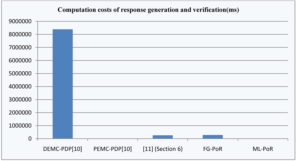
Figure 5.
Computation costs of response generation and verification of the five schemes.
Figure 5.
Computation costs of response generation and verification of the five schemes.


Figure 6.
Storage costs of file blocks and tags of the five schemes.
Figure 6.
Storage costs of file blocks and tags of the five schemes.
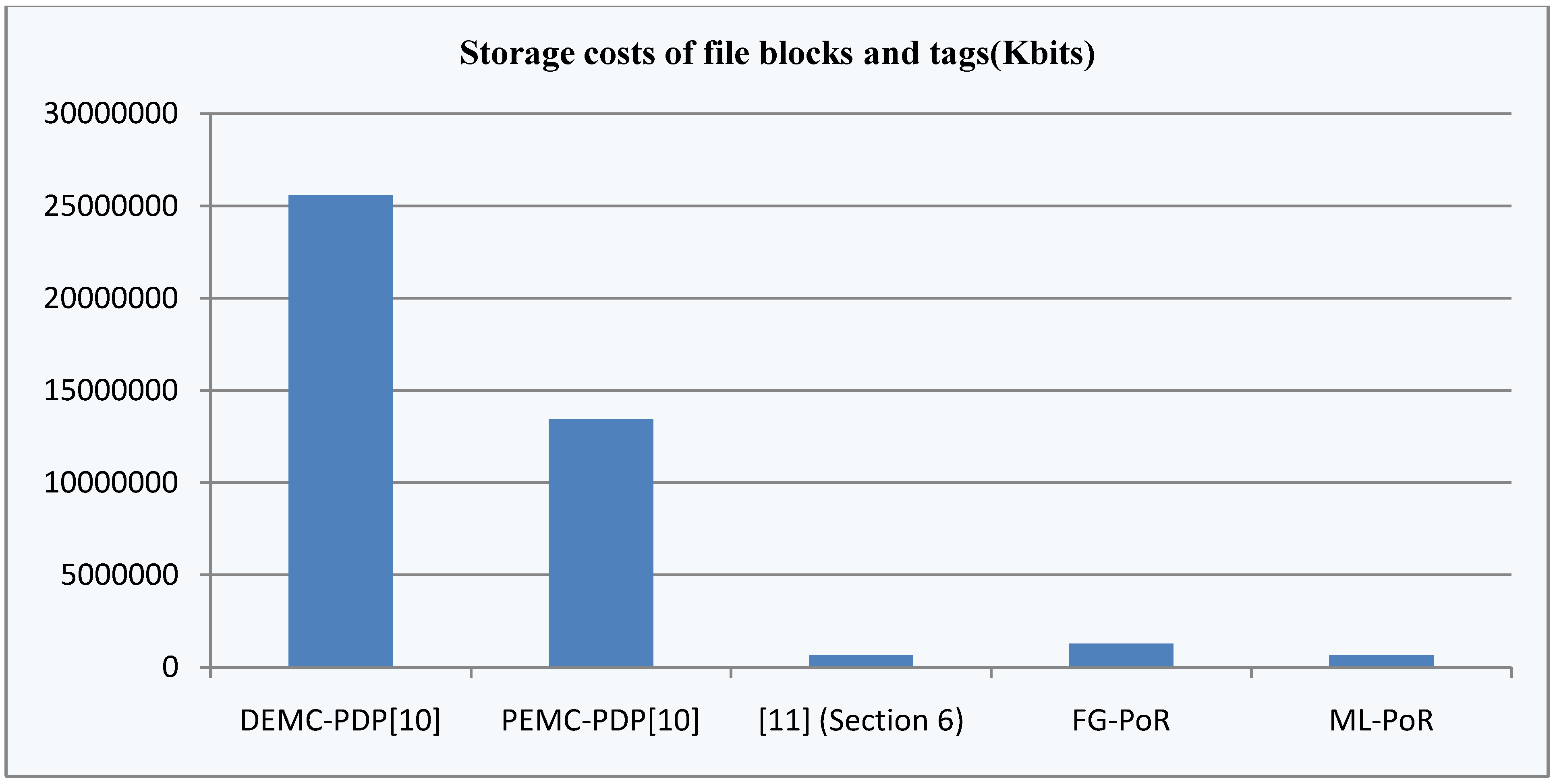
From Figure 6, we know that the storage costs of file blocks and tags of DEMC-PDP [10] and PEMC-PDP [10] are apparently higher than the other three schemes, and the storage costs of DEMC-PDP [10] are highest in all schemes. The storage costs of [11](Section 6) and ML-PoR are roughly equivalent; moreover, the storage costs of ML-PoR are lowest in all schemes.
In five schemes, only [11](Section 6) uses the technologies of encoding and decoding. The [11](Section 6) first applies the erasure codes to encode the file, and then splits encoded file into  sectors. It provides provable data possession and data recovery dual functions, but its erasure of codes adds extra computation costs and storage costs, so the total costs of [11](Section 6) are higher than our FG-PoR and ML-PoR. DEMC-PDP [10] and PEMC-PDP [10] use multi-replication technology to achieve provable data possession and data recovery functions, but storage costs are too high. Also, the computation costs of DEMC-PDP [10] are the highest of the five schemes. Our ML-PoR generates only a tag to each row of evidence matrix, rather than generating a tag to each element of evidence matrix. Therefore, it reduces computation costs and storage costs compared to that of the FG-PoR. In overall performance, ML-PoR is superior to the other four schemes.
sectors. It provides provable data possession and data recovery dual functions, but its erasure of codes adds extra computation costs and storage costs, so the total costs of [11](Section 6) are higher than our FG-PoR and ML-PoR. DEMC-PDP [10] and PEMC-PDP [10] use multi-replication technology to achieve provable data possession and data recovery functions, but storage costs are too high. Also, the computation costs of DEMC-PDP [10] are the highest of the five schemes. Our ML-PoR generates only a tag to each row of evidence matrix, rather than generating a tag to each element of evidence matrix. Therefore, it reduces computation costs and storage costs compared to that of the FG-PoR. In overall performance, ML-PoR is superior to the other four schemes.6. Conclusions
Proofs of Retrievability (PoR) to cloud storage data are mainly based on multi-replication technology and erasure code technology [19]. PoR based on multi-replication technology is required to create some copies of the same size for each data block, so the server needs to provide extra storage space for these copies, such as in the schemes in [9,10]. PoR based on erasure code technology needs to blend some data blocks into less redundant blocks, so it saves storage space, but the encoding and the decoding operation add computation costs, such as in the schemes in [8,11]. This paper proposes two PoR schemes—FG-PoR and ML-PoR—for the storage of electronic evidence in the cloud. The two PoR schemes do not use multi-replication technology or erasure code technology, and the two technologies are replaced by employing verification tags and signatures. Therefore, FG-PoR andML-PoR have lower computation costs and storage costs than other similar schemes. Moreover, they not only can ensure the integrity of electronic evidence, but also provide a robust evidence recovery guarantee.
Acknowledgments
This work is partially supported by Natural Science Foundation of Chongqing Science & Technology Commission of China under Grant No. 2011jjA1350 and No. 2011jjA40031. Science & Technology Research Foundation of Education Committee of Chongqing of China under Grant No. KJ110505, and Found of Innovation Scheme of Postgraduate Education of Chongqing University of Posts and Telecommunications of China under Grant No. Y201107.
Conflict of Interest
The authors declare no conflict of interest.
References
- Chen, L.; Mai, Y.H.; Huang, C.H.; Dong, Z.X.; Shi, W.M.; Song, X.L. Computer Forensics Technology (in Chinese); Wuhan University Press: Wuhan, China, 2007. [Google Scholar]
- Mell, P.; Grance, T. The NIST Definition of Cloud Computing; Special Publication 800–145. National Institute of Standards and Technology: Gaithersburg, MD, USA, 2011. Available online: http://csrc.nist.gov/publications/nistpubs/800-145/SP800-145.pdf (accessed on 20 March 2013 ).
- Kent, K.; Chevalier, S.; Grance, T.; Dang, H. Guide to Integrating Forensic Techniques into Incident Response; Special Publication 800–86. National Institute of Standards and Technology: Gaithersburg, MD, USA, 2006. Available online: http://cybersd.com/sec2/800-86Summary.pdf (accessed on 26 June 2013).
- Wang, C.; Wang, Q.; Ren, K.; Lou, W.J. Ensuring data storage security in cloud computing. In Proceedings of the 2009 17th International Workshop on Quality of Service (IWQos’09), Charleston, SC, USA, 13–15 July 2009; pp. 1–9.
- Taylor, M.; Haggerty, J.; Gresty, D.; Hegarty, R. Digital evidence in cloud computing systems. Comput. Law Secur. Rev. 2010, 26, 304–308. [Google Scholar]
- Ateniese, G.; Burns, R.; Curtmola, R.; Herring, J.; Kissner, L.; Peterson, Z.; Song, D. Provable data possession at untrusted stores. In Proceedings of the 14th Association for Computing Machinery (ACM) Conference on Computer and Communications Security, Alexandria, VA, USA, 29 October–2 November 2007; pp. 598–609.
- Juels, A.; Kaliski, B.S. PORs: Proofs of retrievability for large files. In Proceedings of the 14th Association for Computing Machinery (ACM) Conference on Computer and Communications Security, Alexandria, VA, USA, 29 October–2 November 2007; pp. 584–597.
- Bowers, K.D.; Juels, A.; Oprea, A. HAIL: A high-availability and integrity layer for cloud storage. In Proceeding of the 16th Association for Computing Machinery (ACM) conference on Computer and Communications Security, New York, NY, USA, 9–13 November 2009; pp. 187–198.
- Curtmola, R.; Khan, O.; Burns, R.; Ateniese, G. MR-PDP: Multiple-replica provable data possession. In Proceedings of the 28th International Conference on Distributed Computing Systems, Beijing, China, 17–20 June 2008; pp. 411–420.
- Barsoum, A.F.; Hasan, M.A. Provable possession and replication of data over cloud servers. Available online: http://cacr.uwaterloo.ca/techreports/2010/cacr2010-32.pdf (accessed on 20 June 2013).
- Shacham, H.; Waters, B. Compact proofs of retrievability. In Proceedings of the 14th International Conference on the Theory and Application of Cryptology and Information Security: Advances in Cryptology, Melbourne, Australia, 7–11 December 2008; Springer-Verlag: Melbourne, Australia, 2008; pp. 90–107. [Google Scholar]
- Wang, Q.; Wang, C.; Ren, K.; Lou, W.J. Enabling public auditability and data dynamics for storage security in cloud computing. IEEE Trans. Parallel Distrib. Syst. 2011, 22, 847–859. [Google Scholar] [CrossRef]
- Wolthusen, S.D. Overcast: Forensic discovery in cloud environments. In Proceedings of the Fifth International Conference on IT Security Incident Management and IT Forensics, Stuttgart, Germany, 15–17 September 2009; pp. 3–9.
- Grispos, G.; Storer, T.; Glisson, W.B. Calm before the storm: The challenges of cloud computing in digital forensics. Int. J. Digit. Crime Forensics 2012, 4, 28–48. [Google Scholar] [CrossRef]
- Birk, D.; Wegener, C. Technical issues of forensic investigations in cloud computing environments. In Proceedings of the 6th International Workshop on Systematic Approaches to Digital Forensic Engineering, Oakland, CA, USA, 26 May 2011; pp. 1–10.
- Nyberg, K.; Rueppel, R.A. A new signature scheme based on the DSA giving message recovery. In Proceedings of the 1st Association for Computing Machinery (ACM) Conference on Computer and Communications Security, Fairfax, VA, USA, 3–5 November 1993; pp. 58–61.
- Camenisch, J.L.; Piveteau, J.M.; Stadler, M.A. Blind signatures based on the discrete logarithm problem. In Advances in Cryptology—EUROCRYPT’94: Workshop on the Theory and Application of Cryptographic Techniques Perugia, Italy, May 9–12, 1994. Proceedings; De Santis, A., Ed.; Springer: Berlin and Heidelberg, Germany, 1995; pp. 428–432. [Google Scholar]
- Liu, F.F.; Gu, D.W.; Lu, H.N.; Long, B.; Li, X.H. Reducing computational and communication complexity for dynamic provable data possession. China Commun. 2011, 8, 67–75. [Google Scholar]
- Wang, Y.J.; Sun, W.D.; Zhou, S.; Pei, X.Q.; Li, X.Y. Key technologies of distributed storage for cloud computing. J. Softw. 2012, 23, 962–986. [Google Scholar] [CrossRef]
© 2013 by the authors; licensee MDPI, Basel, Switzerland. This article is an open access article distributed under the terms and conditions of the Creative Commons Attribution license (http://creativecommons.org/licenses/by/3.0/).