1. Introduction
Carbon fiber-reinforced plastic (CFRP) materials are widely used in many industries, owing to their superior strength-to-weight ratio (SWR) compared to conventional steel materials. Recent research has revealed diverse applications of CFRP in research-level activities, such as major components in marine industry [
1], machine tools [
2], crack identification [
3], and guide-wave excitation using angle-beam wedge piezoelectric transducers [
4]. The anisotropic material structure requires a sound understanding of the mechanical properties, and a combination of laminated layouts of CFRP structures may be critical for the determination of physical performance in many situations [
5,
6,
7,
8].
The modal test is a well-known methodology for identifying the dynamic characteristics of a target system under the assumption of linear characteristics in a responsible system. One of the sound advantages of the modal test is a simple testing procedure for the simultaneous measurement of force and response signals using an impact hammer or exciter [
9,
10]. In particular, several novel identification methods of damping elements were proposed in previous studies [
11,
12,
13], and the modal test is an efficient method to measure it as modal damping ratios. As the dynamic nature of CFRP structures is a significant issue in field problems, modal tests have been conducted for target CFRP systems [
14,
15,
16,
17,
18]. Using modal analysis, the modal parameters of the CFRP structure can be identified. These are the representative system parameters in a modal coordinate comprising the resonance frequency, mode shape, and modal damping ratio. The CFRP materials have a high modal damping ratio owing to their binding matrix, whose damping capacity is stronger than that of conventional light-damping steel materials [
19,
20]. Therefore, the controllability of noise or vibration is fine in CFRP structures because the excitation energy is well dissipated, with the structure damping itself.
The modal parameters are not theoretically altered for the external condition, owing to the nature of the system parameters, except for a spectral loading pattern [
21]. However, the sensitivity of modal parameters of anisotropic materials, such as CFRP, was considerable for several conditions, e.g., carbon fiber angle, temperature, and spectral loading pattern. The characteristics of CFRP materials are dependent on the direction of the carbon fiber, while the binding matrix is affected by the service temperature. The effects of the three parameters, carbon fiber angle, temperature, and spectral loading pattern, on CFRP materials were investigated using a uniaxial excitation test for simple rectangular specimens [
22,
23,
24]. Both the resonance frequency and modal damping ratio were obtained from the representative frequency response functions (FRFs), and the variations in the two modal parameters were discussed based on the different carbon fiber angles. In a recent study, the modal parameters of CFRP specimens were more reliably obtained through a modal analysis of clamped simple CFRP specimens at room temperature [
25]. A modal analysis was applied to an isotropic material specimen, SCS13A, and five CFRP specimens with different carbon fiber angles: 0°, 30°, 45°, 60°, and 90°. In the abovementioned study, a comparison of modal parameters was conducted using only the modal assurance criterion (MAC) between a SCS12A specimen and CFRP specimens; hence, the detected additional modes in CFRP specimens could not be well explained by the limited comparison indicator of the MAC [
25]. In this study, three comparison indicators were applied to compare the modal parameters of an isotropic SS275 specimen and CFRP specimens for five different carbon fiber angles. The mode parameters of the SS275 specimen were assumed to be changed, but we managed to trace them even for CFRP specimens since the shape of the specimens were the same (a simple rectangle) with differences only in the applied materials. The main focus was the sensitivity of modal parameters over the different carbon fiber angles at the same structural configuration; variations in the parameters will not be traceable if the shape of the specimen or the clamping boundary conditions are changed from the reference case. The boundary condition of the specimens was prepared as a free-free boundary condition to investigate the influence of the modal parameters on the carbon fiber angle without the effect of the clamped zone. As the resonance frequency of the CFRP specimen changed rapidly and showed different variation patterns in each mode according to the carbon fiber angle, the mode tracking for the five modes of the CFRP specimen could be successfully achieved using two types of modal parameters: the resonance frequency and modal damping ratio, and the MAC value. The variation in resonance frequency was very sensitive for all carbon fiber angles since the structural stiffness was closely related to the carbon fiber angle. Two other indicators were complementary indicators for selected modes of interest; the MAC value and the modal damping ratio were efficient for bending and torsional modes, respectively. All the indicators were proven through the mode tracking of measured modal parameters of CFRP specimens over different carbon fiber angles. In particular, the MAC value was previously used for the comparison of mode shapes of the clamped specimens by both the isotropic SCS13A and the CFRPs and was proven to be a useful indicator for the bending modes of interest [
25]. The mode order shift was observed in the five tracked modes of the CFRP specimen. The first bending mode in the CFRP specimen with 0° was found to be the shifted bending mode of the third bending mode in the SS275 specimen. The rapidly shifted resonance frequencies could be explained by the structural stiffness condition according to the carbon fiber angle. The novelty of this study is the use of the mode tracking method for the highly sensitive CFRP structure over the carbon fiber angle using three indicators, namely the variation in resonance frequency, the modal damping ratio, and the MAC value. In particular, understanding the dynamic behavior of CFRP with varying carbon fiber angles promotes the effective design of the stacking layer of composite CFRP structures. The study proposes an efficient method to determine the variation in modal parameters in CFRP structures using multiple indicators. However, as the three indicators are well-known modal parameters or the criteria for modal validation, each indicator exhibits a slight similarity to previous studies. In addition, the sensitivity results may change if the configuration of the specimen changes from the study case.
2. Theoretical Background for Mode Tracking Indicators
Modal analysis is a well-known system identification method for linear systems. It is easy to calculate modal parameters, both the resonance frequency and the modal damping ratio, from measured FRFs. As the FRF can be assumed to be the dynamic characteristics of the target system, the ratio between the impact force and responses should be invariant, even for variant input force conditions. If the target system is a linear time-invariant (LTI) system, one FRF
can be represented using two modal parameters, i.e., both resonance frequency
and modal damping ratio
, at the
i-th mode, as described in Equation (1). Here, the FRF in Equation (1) is dependent on the location between one input position and one response position [
12,
13]:
where
,
, and
are the frequency parameter, normalized residual, and imaginary unit, respectively. The resonance frequency can be found at the peak points in the FRF, and
corresponds to the
ith peak. The modal damping ratio can be obtained using two half-power points at the resonance frequency of interest, and the
i-th modal damping ratio
can be determined from Equation (2) [
12,
13]:
where both
and
are the two half-power points from
, and
denotes the absolute value of variable
a. Equations (1) and (2) from the LTI system are normally valid for isotropic materials; hence, the FRF should be revised if the target system is applied for anisotropic materials, such as CFRP. For the FRF equation for CFRP materials, previous studies modified Equation (1) using three parameters: carbon fiber angle
, temperature
, and spectral loading pattern
, as described in Equation (3) [
22,
23,
24]:
Therefore, the FRF for the CFRP material can be simply reformulated as in Equation (4) if the input force is given as the impact pattern and the operating temperature is fixed at room temperature:
The
MAC is an effective indicator for the similarity between two mode shape vectors and can be defined as follows using two mode shape vectors,
and
[
12,
13].
Here, is the transpose of and is the complex conjugate of . The two mode shape vectors can be used for the same target system. The maximum value is 1 if i = j. Normally, as a rule of thumb, a two-mode shape is well matched for MAC greater than 0.7, while the similarity of each mode shape is rejected for MAC less than 0.4.
The most efficient indicator of mode order shift of CFRP specimens was the resonance frequency because the structural stiffness is very sensitive to the direction of the carbon fiber in CFRP structures. The structural stiffness of the CFRP structure is closely related to the shape in each mode, so that the variation in resonance frequencies is a unique characteristic of each mode. The other two indicators, the MAC value and the modal damping ratio, were used complementarily for the selected modes of interest; the MAC value is efficient for the mode trace of bending modes and the variation in modal damping ratio is useful for the torsional modes. All indicators were proven from the measured modal parameters of CFRP specimens under free-free boundary conditions in this study. A previous study only considered the MAC value for the mode tracking of CFRP specimens and did not consider the mode order shifting effect [
25]. Therefore, a comparison of modes between the different specimens was performed in a fixed mode order combination, and the order shifted mode from a higher mode was regarded as an additional mode derived from the complex composite CFRP structure.
The proposed mode tracking of CFRP specimens was conducted as follows. The three indictors were calculated from the measured FRF or modal parameters. Then, mode tracking was conducted by using the variation in resonance frequencies in each mode. Simultaneously, the variations in the other two complementary indicators were also calculated for the tracked mode orders. The variation in resonance frequency in each mode should be explained by the change in structural stiffness over the carbon fiber angle as considering the identified mode shape. The MAC value was used for the calculation of the tracked bending modes and variation in the modal damping ratio was applied for the validation of tracked torsional modes.
3. Modal Test for Simple Rectangular Specimens
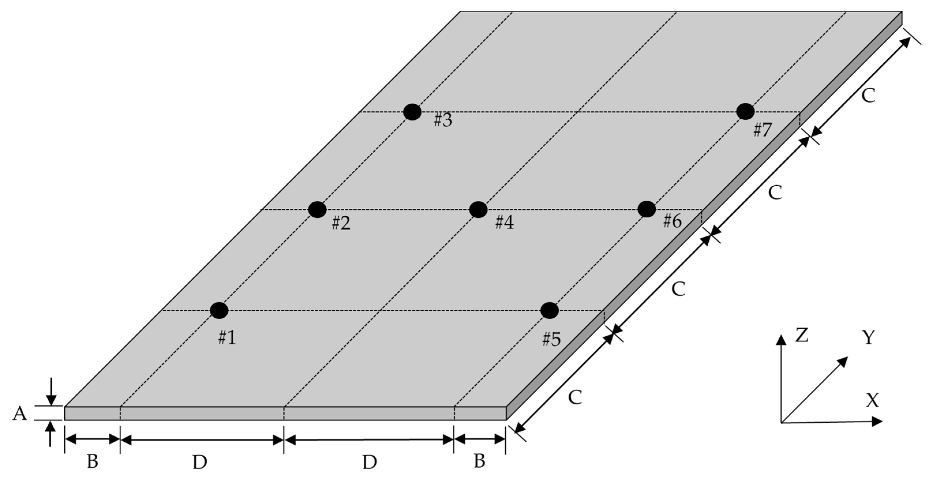
A simple rectangular specimen was prepared to identify the modal parameters, resonance frequency, modal damping ratio, and mode shape vector using an experimental impact test. For the simple rectangular specimen, the isotropic material was prepared using the widely used carbon steel, SS275 (POSCO, Pohang, South Korea), while the CFRPs were used as the anisotropic materials. The size of the specimens, both SS275 and CFRP, was 80 mm (W) × 150 mm (L) × 3 mm (H), as illustrated in
Figure 1. We designed a simple specimen configuration to prevent the influence of structural shape on the dynamic response of test specimens. Five CFRP specimens with different carbon fiber angles (0°, 30°, 45°, 60°, and 90°) were prepared by cutting them from a large unidirectional (UD) CFRP composite panel, as shown in
Figure 2. The SS275 carbon steel was manufactured using a cold-rolling process. The UD composites were manufactured by an autoclaving process from 12 layers of USN 250A, which is a pre-implemented composite fiber (thickness: 0.258 mm) made by SK Chemical, Seongnam, South Korea, as illustrated in
Figure 2 [
26]. We performed autoclave-based curing at 125 °C in two steps of 30 and 90 min. The USN 250A was composed of a T700 carbon fiber (12k, Toray, Tokyo, Japan) and a binding matrix (epoxy resin).
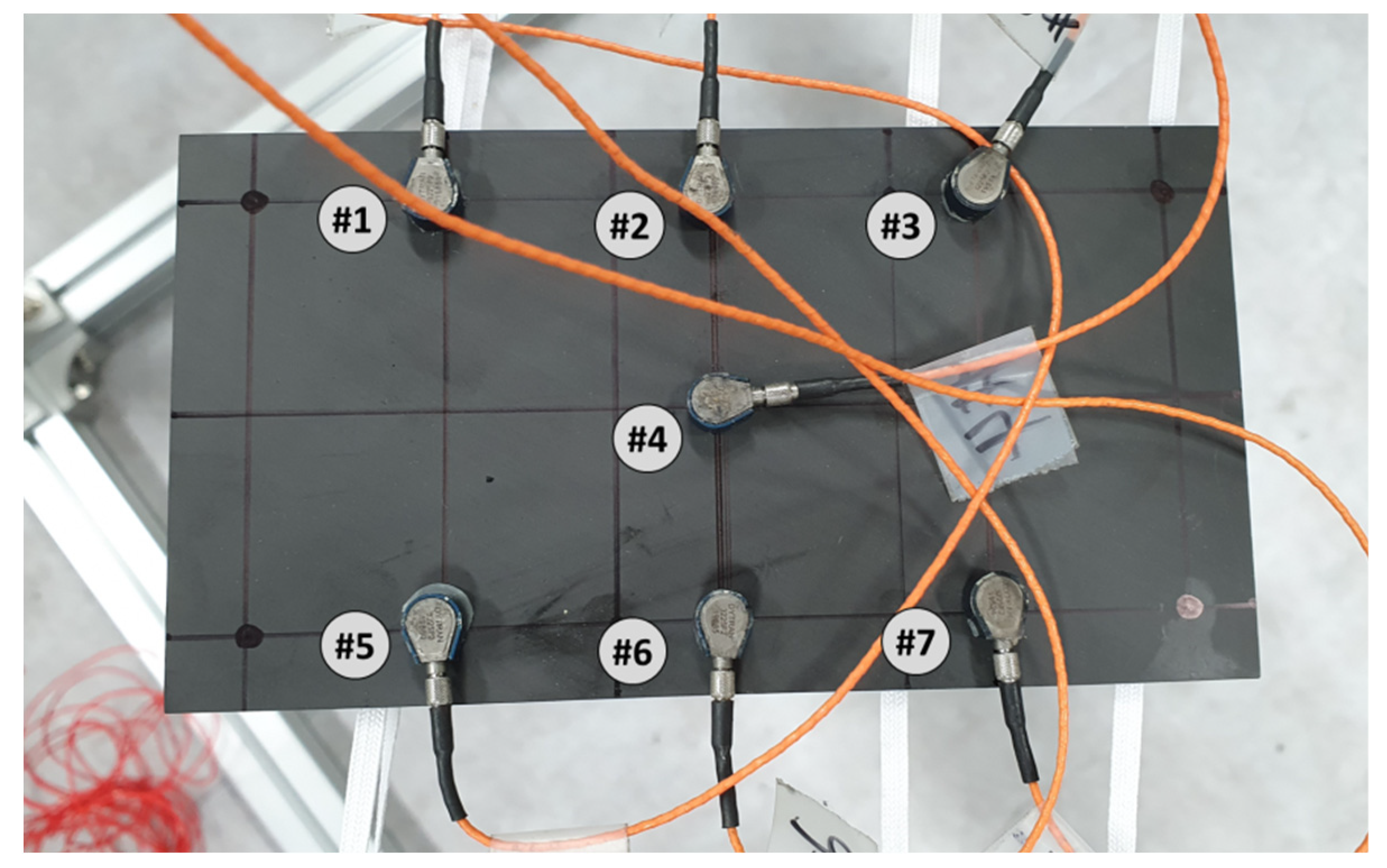
The data acquisition equipment used was an eight-channel LMS SCADAS mobile (Siemens, Munich, Germany) with a VB8-II input module, such that the maximum number of response channels was seven, with one channel reserved for the impact force signal. The seven sensor locations shown in
Figure 1 were used to measure the dynamic response of the SS275 specimen and the specific locations were preselected considering the mode shape. The mode shape of the simple rectangular specimen was predicted using a theoretical modal analysis employing a finite element (FE) model. The FE model of the isotropic SS275 specimen was constructed with tetra elements using HyperWorks software (Altair, MI, USA). We selected auto mesh processing to generate an FE model by using a CAD model, and the tetra mesh size was set at 2 mm. The FE model size was the same as the size of the SS275 specimen, i.e., 80 mm (W) × 150 mm (L) × 3 mm (H). The theoretical modal analysis was conducted using Virtual.Lab software (Siemens, Munich, Germany) under no-constraint and no-damping coefficient conditions. The frequency limit of the modal analysis was set to 5000 Hz, considering the maximum limit of the frequency range at the accelerometer. The default mechanical properties of SS275, density, modulus of elasticity, and Poisson’s ratio, were set to 7850 (kg/m
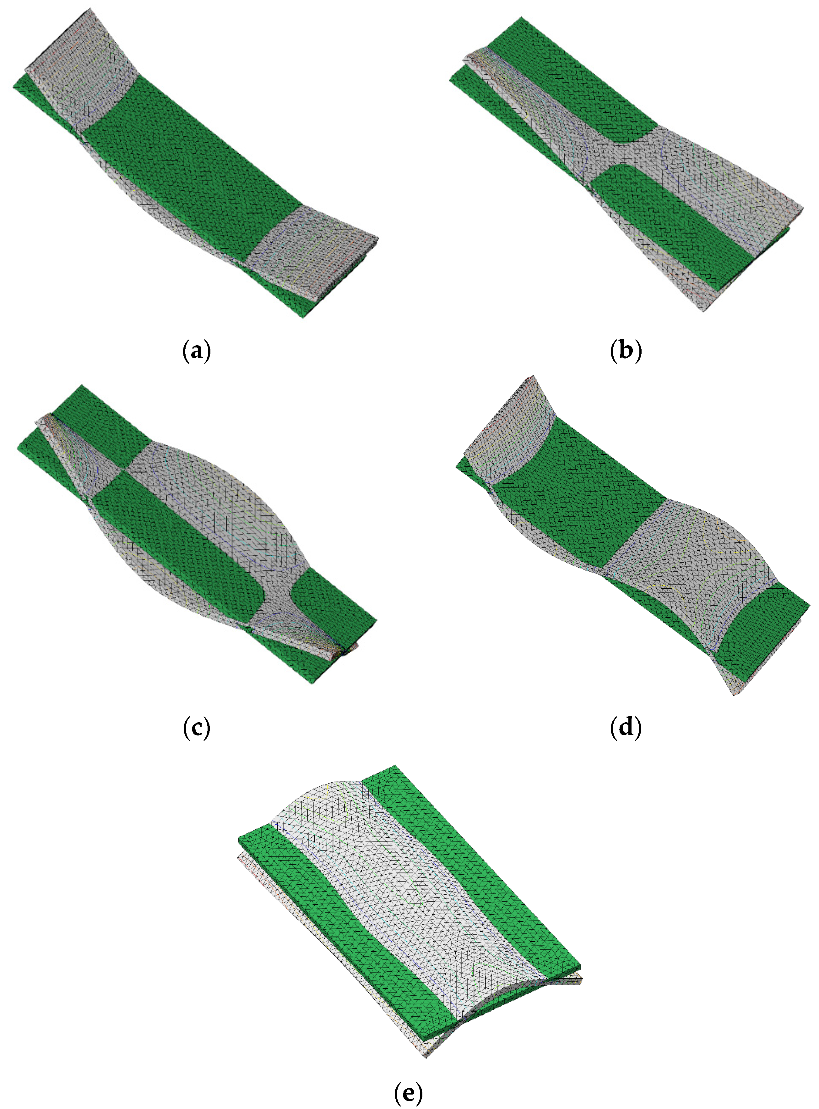
3), 210 (GPa), and 0.3, respectively. We manually selected the elasticity moduli for updating the original FE model, while the applied modal damping ratios were obtained from the experimental modal test. The resultant mode shapes of the SS275 specimens are shown in
Figure 3.
The five mode shapes of interest revealed that the sensor location in
Figure 1 is appropriate to represent the responsible motion of the SS275 specimen as the nodal lines (zero movement line) in all mode shapes showed minimum matching with the sensor locations. This indicates that the measured response from the seven sensor locations shown in
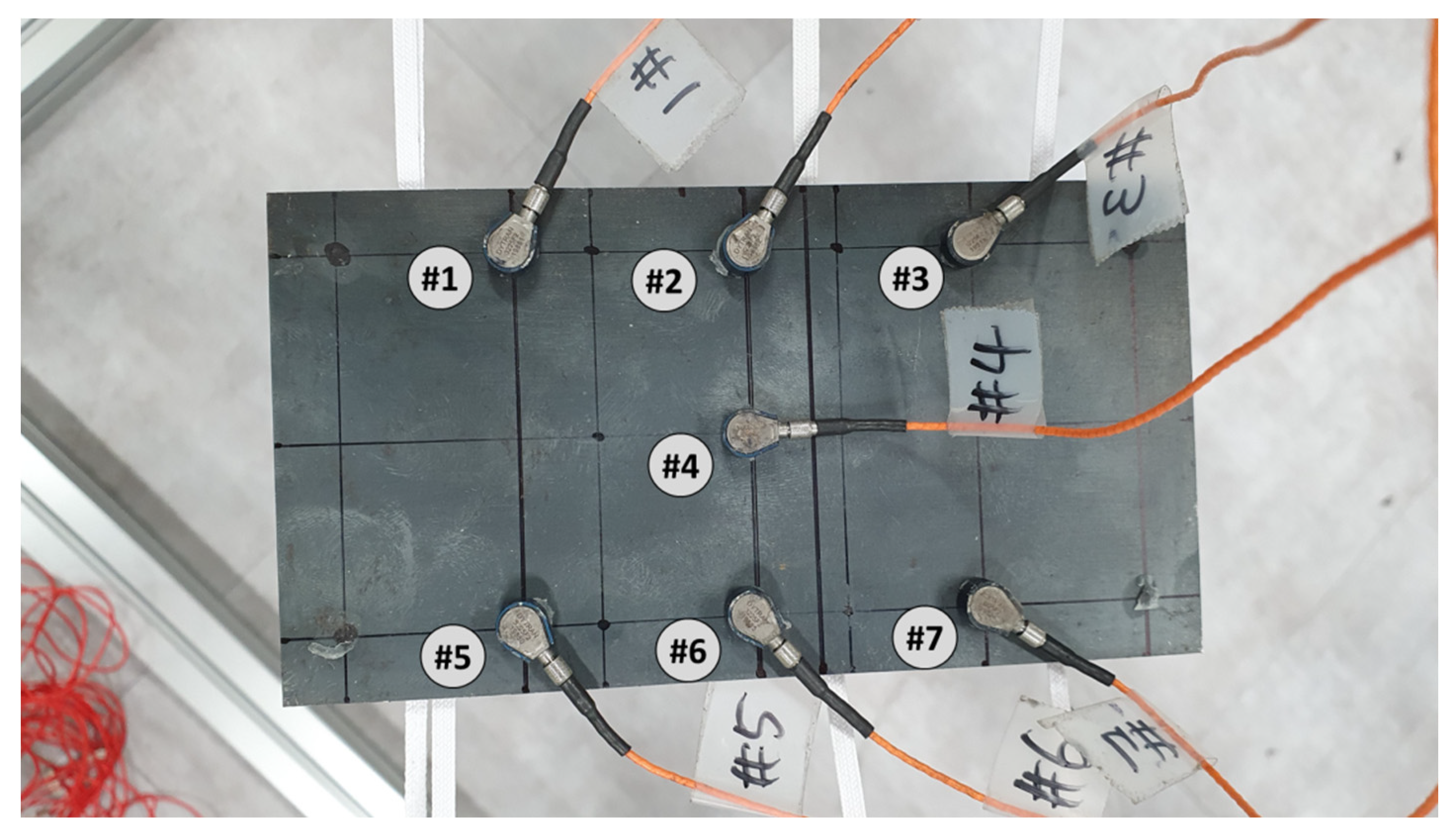
Figure 1 might have sufficient information to represent the five mode shapes of interest. The validation of sensor locations was reconfirmed through a comparison with experimental results. The experimental modal parameters of the SS275 specimen were identified using the impact test, and the modal analysis was performed using TestLab software (Siemens, Munich, Germany). The boundary condition of the SS275 specimen was set as free-free by placing the specimen on a rubber band whose stiffness is very low, as shown in
Figure 4. The additional stiffness contributed by the rubber band was low enough to be disregarded. The impact force was assigned using an impact hammer (Model: 5800B3, Dytran, Chatsworth, CA, USA), and the response data were obtained using a uniaxial accelerometer (Model: 3225F2, Dytran). The accelerometer was attached to beeswax (Dytran, Chatsworth, CA, USA) to minimize the influence of the increase in stiffness on sensor location. The mass loading effect from the accelerometer can be neglected because the total weight of the CFRP specimen (=56.5 g) was sufficiently higher than that of the weight of seven accelerometers (=1 g × 7 = 7 g). A fixed hammer option (set to #4 with a minus z direction, see
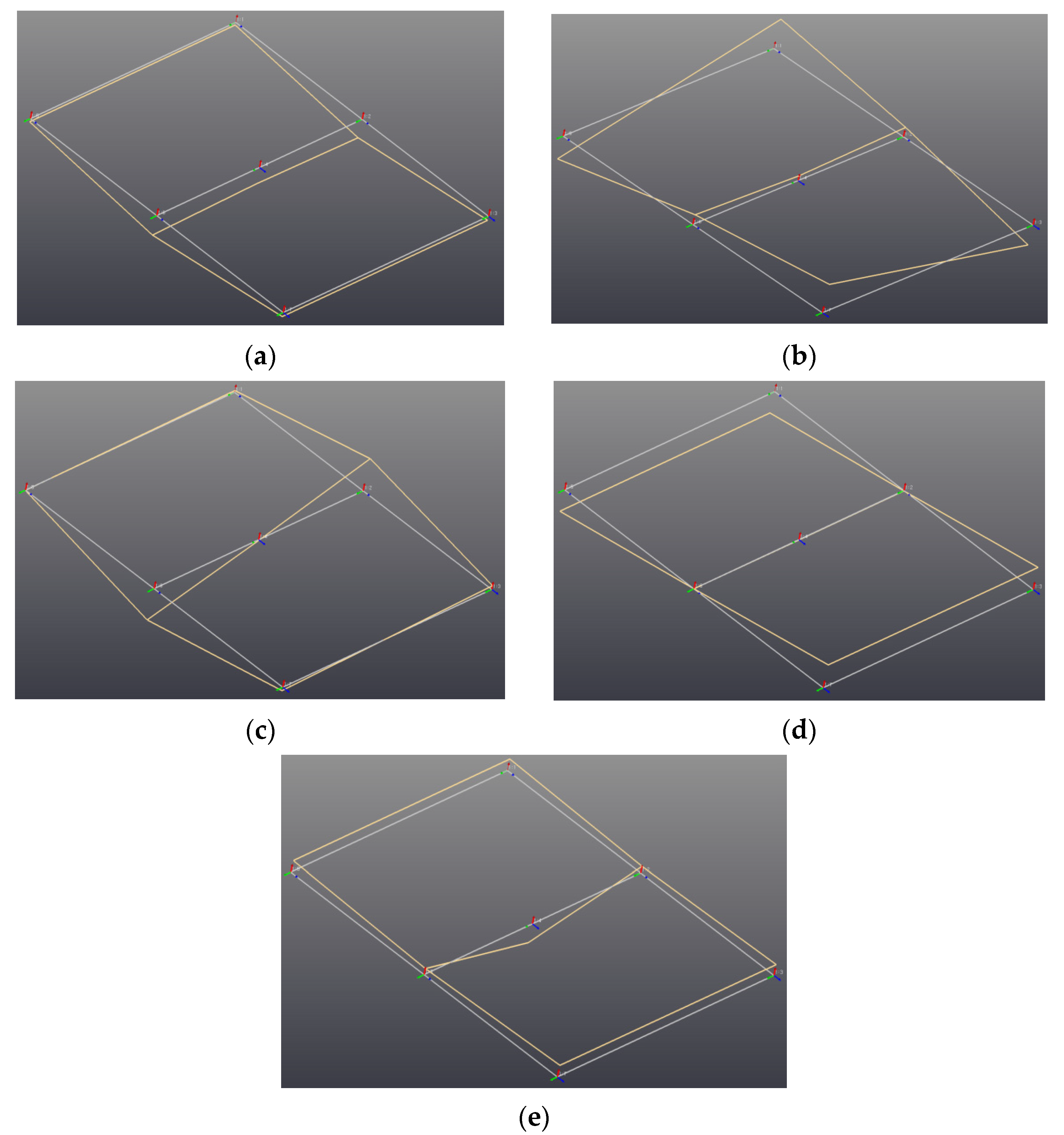
Figure 1) was applied for the impact test, and the FRFs were measured 10 times between 10 and 3000 Hz. We selected reliable FRFs, exhibiting coherence function values higher than 0.95 at all resonance frequency points to ensure precise measurements. The modal parameters were calculated using the PolyMAX algorithm in the TestLab software (Siemens, Munich, Germany). The identified modes were validated using their MAC values, and all redundant modes with MAC greater than 0.4 were eliminated. The first five modes identified are illustrated in
Figure 5.
The correlation of the modal parameters for the SS275 specimen was determined using the model correlation module in TestLab software; the results are summarized in
Table 1. The current FE model was updated by changing the elastic modulus. The modal parameters of the FE model listed in
Table 1 were derived from the revised FE model. The three bending modes determined by the FE model matched well with the experimental values. The first torsional mode was marginally acceptable at 0.65, whereas the model and experimental values agreed well for the second mode. All the resonance frequencies also had a minimum error between the FE model and experimental cases, except for the first torsional mode, which had an error of 6.5%. The relatively large error in the first torsional mode indicates the limitation of the seven uniaxial accelerometers to cover all the five mode shapes; however, the sensor locations could be acceptable for the locations shown in
Figure 1 as the other four modes showed an accurate correlation between the model and experimental values.
An experimental modal test was applied to the five CFRP specimens under different carbon directions. All the options of test setup and analysis were the same as in the previous SS275 specimen case. The experimental setup for the CFRP specimen is shown in
Figure 6. The boundary condition for the experimental impact test was set as a free-free condition using the same rubber band, and the impact point was similarly set to #4. The experimental results for the CFRP specimens are presented in
Table 2.
The SS275 specimen (see
Table 1) exhibits significantly lower modal damping ratios than the CFRP specimens (see
Table 2) for all modes. Thus, the CFRP material is industrially desirable because of its higher energy dissipation capacity under excitation than that of conventional steel (SS275).
4. Comparison of Modal Parameters
The mode shape was compared using the MAC values of the SS275 specimen and the five CFRP specimens. In addition, the variation in the modal parameters, i.e., both the resonance frequency and modal damping ratio, were also tracked for all the identified parameters listed in
Table 2. Using the MAC value, the three bending modes matched well in three cases, i.e.,
and
, but not at
. The MAC value for the two torsional modes showed a relatively high value at
, but was not remarkable even for the two cases. The variation in resonance frequency was a more efficient indicator than the MAC value as all the resonance frequencies decreased with increasing carbon fiber angle, except for the second torsional mode. For the second torsional mode, the minimum resonance frequency was at
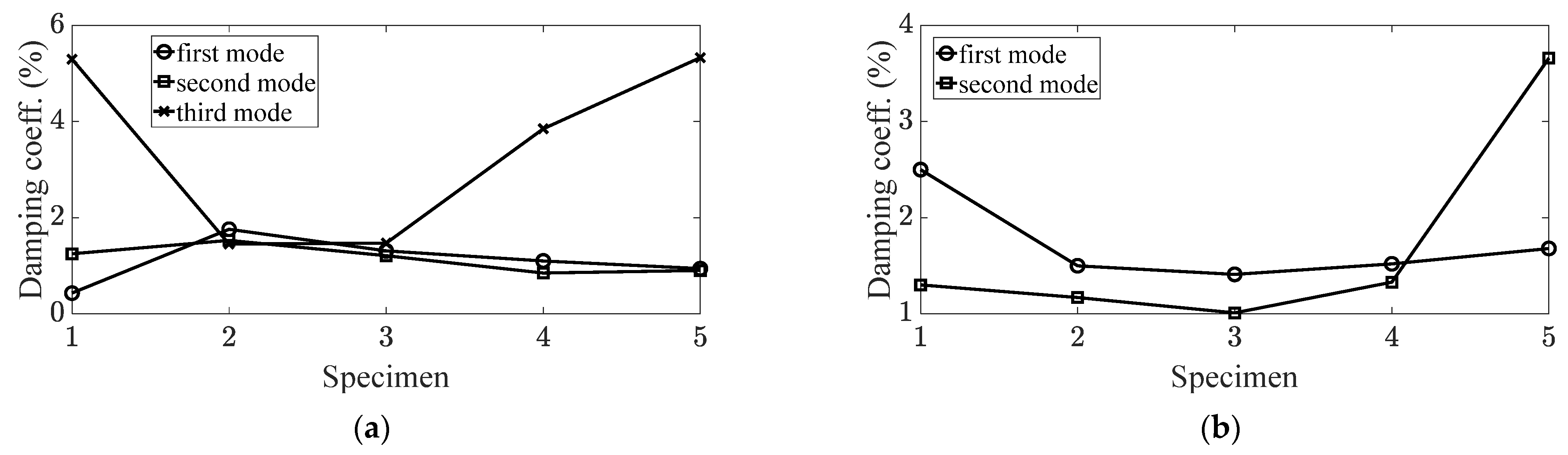
, and this value increased when the carbon fiber angle was increased or decreased. The variation in the modal damping ratio was effective for the two torsional modes as the minimum values were all observed at
and increased for values away from
. The results of mode tracking for the five modes of interest using the three indicators are summarized in
Table 3. The ascending mode order was selected from the mode order of the SS275 specimen by first bending, first torsional, second torsional, second bending, and third bending. Here, the number in the CFRP specimen denotes the carbon fiber angle; the carbon fiber angle from
to
corresponds to the simple CFRP specimen from #1 to #5. The variations in the resonance frequency and modal damping ratio are shown in
Figure 7 and
Figure 8, respectively.
Each mode demonstrated different sensitivities of modal parameters, resonance frequencies, and modal damping ratios along the carbon fiber angle. The variation in the resonance frequency can be explained by the mode shape or maximum structural stiffness condition in each mode. For the first two bending modes, the structural stiffness was at a maximum at the carbon fiber with
; hence, the resonance frequency decreased from
to
. Contrastingly, the structural stiffness was at a maximum at
° for the third bending mode; thus, the resonance frequency increased from
to
. For the first torsional mode, the maximum structural stiffness occurred at
°, as the width (80 mm) was relatively shorter than the length (150 mm) of the specimen, shown in
Figure 1. For the second torsional mode, the explanation was more complicated, owing to the complex mode shapes. The torsional mode was found at the edge of the specimen, whereas the bending mode was found near the center. Therefore, the carbon fiber affected the torsional mode in cases with a small direction (i.e.,
) and contributed to the bending mode in cases with a large direction (i.e.,
). Thus, a variation in the resonance frequency appeared in two phases. The variation in the modal damping ratio could not be explained using mode shape as the variation in the trend of the resonance frequency did not match with the modal damping ratio.
The tracked modal parameters at several modes of interest gives insight to understand the variation in dynamic behavior of carbon-reinforced composites over different carbon fiber angles so that the design of dynamic characteristics of the responsible composite structure can be reasonably achieved by the control of a carbon fiber angle in the layered composite structure. In addition, the reliable tracked modal parameters from the proposed method can be used to validate theoretical models (FE model).


