Abstract
The maritime industry faces significant challenges from energy consumption and air pollution. Fuel cells, especially hydrogen types, offer a promising clean alternative with high energy density and rapid refueling, but their slow dynamic response necessitates integration with lithium batteries (energy storage) and supercapacitors (power storage). This paper investigates a hybrid vessel power system combining a fuel cell with a Hybrid Energy Storage System (HESS) to address these limitations. An improved droop control strategy with adaptive coefficients is developed to ensure balanced State of Charge (SOC) and precise current sharing, enhancing system performance. A comprehensive protection strategy prevents overcharging and over-discharging through SOC limit management and dynamic filter adjustment. Furthermore, the Parrot Optimization Algorithm (POA) optimizes HESS capacity configuration by simultaneously minimizing battery degradation, supercapacitor degradation, DC bus voltage fluctuations, and system cost under realistic operating conditions. Simulations show SOC balancing within 100 s (constant load) and 135 s (variable load), with the lithium battery peak power cut by 18% and the supercapacitor peak power increased by 18%. This strategy extends component life and boosts economic efficiency, demonstrating strong potential for fuel cell-powered vessels.
1. Introduction
Advances in clean energy technologies have spurred significant interest in alternative vessel propulsion, but practical implementation of fuel cell-powered systems requires sophisticated solutions to address their inherent limitations [1]. The performance of hybrid energy storage systems (HESS) in fuel cell vessels is critically limited by conventional droop control, which struggles to balance voltage regulation with accurate power-sharing among storage units under dynamic maritime conditions. To overcome this, this paper introduces an integrated framework featuring an adaptive droop control strategy for real-time state-of-charge (SOC) balancing, coupled with the Parrot Optimization Algorithm (POA) for optimal HESS capacity configuration, aiming to enhance both system dynamic response and economic efficiency. Fuel cells, functioning as clean energy conversion devices that utilize hydrogen fuel, are increasingly applied in vessels due to their high electrical efficiency, rapid refueling capability, and the high specific energy of fuel that enables extended zero-emission operations [2]. However, under diverse operating conditions (normal sailing, berth, landfall and offshore), vessels have different requirements for the power. Fuel cells exhibit slower dynamic response than batteries, limiting their ability to meet fluctuating vessel power demands. Consequently, a hybrid power system composed of a fuel cell and a Hybrid Energy Storage System (HESS) (lithium battery and supercapacitor) has emerged and is continuously being improved [3]. The energy-type device, lithium battery, can provide a stable and sustained energy output owing to its high energy density; the power-type device, supercapacitor, would effectively mitigate sharp power fluctuations due to the high power density and rapid response. Unfortunately, there may be differences in State of Charge (SOC) between different energy storage units, which can lead to issues such as overcharging or over-discharging. These problems not only accelerate the aging, reduce the performance, shorten the lifespan of energy storage devices, but also affect the stability of the vessel power system and even pose risks to vessel operations [4]. Therefore, many researchers propose different solutions to mitigate the situation.
Among existing control methods, the droop control is widely used to prevent overcharging and over-discharging. The inherent control algorithm intrinsically couples SOC with the output power, which enables autonomous power regulation without the need for communication links [5]. However, the conventional droop control faces significant challenges in complex and large-scale systems. It often cannot simultaneously achieve small voltage deviation and high current-sharing accuracy. This limitation may lead to system instability and reduced battery lifespan, consequently restricting its application in demanding scenarios [6]. Therefore, there is an urgent need for the improvement of the conventional droop control to address these issues. Wang et al. [7] introduced a SOC-based power exponential function droop control. It improves the power distribution among multiple energy storage units and resolves the inherent imbalance in the conventional droop control due to the neglect of SOC. Their experimental validation showed that the proposed strategy accelerated the SOC balancing process by approximately 60%, reduced the convergence time for SOC equalization from about 200 s (conventional method) to 80 s under a step-load change, and maintained the AC bus voltage deviation within ±0.5% of the nominal value, thereby significantly enhancing both the autonomy and stability of the islanded AC microgrid. Firmansyah R et al. [8] proposed a new adaptive droop control strategy that adjusts the droop coefficient online. Their simulation results demonstrated that this strategy reduced the current-sharing error among converters by 34% and improved the DC bus voltage restoration, limiting the steady-state deviation to within 0.5% of the nominal voltage, thereby significantly enhancing both power-sharing accuracy and voltage regulation capability compared to conventional methods. Deng et al. [9] combined adaptive droop coefficients with inner-loop power-voltage derivative regulation to achieve maximum power point tracking and DC bus voltage support. Their simulation results demonstrated that the proposed strategy reduced the system response time to power changes by approximately 40%, improved the maximum power point tracking efficiency to 99.2%, and maintained the DC bus voltage deviation within ±0.8% of the nominal value under varying solar irradiation, significantly enhancing the dynamic performance and voltage stability of the distributed photovoltaic system. Kulkarni S V et al. [10] incorporated virtual impedance into the conventional droop control to achieve frequency/voltage restoration and more precise power sharing in parallel converter systems. Their simulation studies demonstrated that the proposed strategy reduced the steady-state frequency and voltage deviations by more than 65% compared to the conventional droop method. Specifically, it improved the active power sharing accuracy among parallel converters to within 98.5%, while simultaneously enhancing the system’s dynamic response by reducing the settling time for voltage restoration by approximately 50% during load transients. Mohammadi F et al. [11] proposed an improved droop control strategy that achieves coordinated control of active/reactive power distribution and voltage/frequency regulation in multi-terminal high-voltage direct current systems without communication by synchronously considering AC voltage, DC voltage and frequency droop. Their simulation results validated that the proposed method reduced the power sharing error among terminals by over 40% compared to conventional droop schemes. Furthermore, it enhanced the system’s dynamic stability by reducing the DC voltage overshoot during load steps by approximately 60% and improved the recovery time for frequency deviations by more than 50%, thereby demonstrating superior coordinated performance without relying on communication links.
Indeed, Lu et al. have proposed different improvements for the conventional droop control [12]. However, the fundamental issues of reducing voltage deviation and improving current sharing accuracy simultaneously in the conventional droop control still need further research [13]. Consequently, this paper proposes an improved droop control method that combines the SOC of every energy storage unit with the relative droop coefficient, allowing the coefficient to adapt responsively to SOC variations. This proposed method could satisfy the requirements for high current-sharing accuracy, small voltage deviation, and SOC balancing between different energy storage units, thereby ensuring the safe and stable operation of the vessel’s power system.
The entire vessel propulsion system not only needs to ensure operational reliability but also consider cost-effectiveness [14]. Fuel cells, which electrochemically convert hydrogen fuel into electricity, are increasingly applied in vessels due to their high electrical efficiency and zero local emissions. When integrated with hydrogen storage systems, they also benefit from the high specific energy of hydrogen, which enables extended zero-emission operations, and from the rapid refueling capability of gaseous hydrogen; however, they typically exhibit slow dynamic response, making it difficult to meet the fluctuating power demands of vessels [15]. While supercapacitors have the benefits of high-power density, fast charging and discharging, long lifespan, and high efficiency, their lower energy density limits their ability to store large amounts of energy for extended periods [16]. Therefore, many scholars have studied the capacity configuration of Hybrid Energy Storage Systems (HESS) composed of a lithium battery and supercapacitor, as a reasonable configuration can effectively reduce the cost of HESS and save space on the vessel [17]. Li et al. [18] optimized the capacity allocation of the vessel HESS through a multi-objective optimization model and genetic algorithm, enhancing both cost-effectiveness and system reliability. Their case study results demonstrated that the proposed optimization framework reduced the total cost of the HESS by approximately 15.3% compared to an empirical sizing method, while simultaneously decreasing the battery power fluctuation by 32.7%. Jing et al. [19] proposed a two-level optimization model based on integrated scenario planning. This model combines the hydrogen energy storage system and supercapacitor to optimize the capacity configuration of integrated vessel power systems, thereby significantly improving the return on investment. Their case study demonstrated that the optimized system configuration reduced the total lifecycle cost by approximately 18.7% compared to a conventional battery-only storage design. Huang et al. [20] introduced an adaptive joint optimization framework that considers the load fluctuation characteristics in the propulsion system. By coupling capacity configuration and energy management strategies, it optimizes the lifecycle costs and battery degradation. Their results demonstrated that this coupled approach reduced the total lifecycle cost by approximately 16.5% and attenuated battery capacity degradation by 24.3% over a 10-year period compared to a sequential design method. Zhang et al. [21] presented a capacity allocation model for HESS of a wind and wave energy integrated vessel power system. It reduces the system costs and space occupation through multi-objective optimization. Their case study demonstrated that the optimized HESS configuration achieved a system cost reduction of 14.2% and a physical footprint reduction of 21.8% compared to a baseline oversized design. The model optimally allocated 35 kWh of lithium battery capacity for bulk energy storage and 8.5 kWh of supercapacitor capacity for high-frequency power smoothing, which together maintained the DC bus voltage fluctuation within ±2.5% under variable renewable generation, effectively balancing economic, spatial, and power quality objectives. Barrera-Cardenas R A et al. [22] proposed a two-stage optimization process based on the Pareto optimization algorithm. It considers capacity configuration, energy management system, and equipment degradation, to construct an optimal solution set for HESS in all-electric vessels. Their analysis on a ferry case study generated a Pareto front where optimal solutions reduced the total system cost by 12–22% and extended the battery cycle life by 15–30%, compared to a reference single-objective design. Li et al. [23] introduced a HESS capacity allocation method based on lifecycle cost optimization. It optimizes the power distribution through operating condition segmentation and empirical mode decomposition. Their case study on a coastal vessel demonstrated that this method reduced the total lifecycle cost by approximately 17.5% compared to a rule-based sizing approach.
In conclusion, existing research has made significant progress in the power allocation of vessel HESS. However, these methods generally rely on static or limited scenario assumptions. When the system scale expands and operational scenarios become more complex, the conventional optimization algorithms face challenges in global search capability, convergence speed, and solution accuracy when solving such multi-objective joint optimization problems.
The Parrot Optimization Algorithm (POA) is a heuristic optimization algorithm inspired by the foraging behavior of birds in nature. In multi-objective optimization, complex systems, and dynamic environments, the POA has become an effective tool for addressing complex optimization problems due to its adaptability and efficiency [24]. The POA can adaptively adjust its optimization strategy to handle complex objectives such as power distribution, SOC balance, and system response speed. By leveraging its highly efficient global optimization capabilities, POA holds promise in overcoming the limitations of traditional optimization methods when handling complex constraints and large-scale systems. In light of this, this study introduces POA to the capacity allocation optimization problem of vessel HESS, aiming to explore its effectiveness in this specific engineering application [25].
This paper establishes an integrated control and optimization framework, validated through a case study of the new energy vessel Alsterwasser. The subsequent structure of this paper is as follows: Section 2 lays the foundation by establishing a hybrid propulsion system model, detailing the operational characteristics of fuel cells, lithium-ion batteries, and supercapacitors. Based on this model, Section 3 proposes an improved droop control strategy with adaptive coefficients to achieve rapid state-of-charge (SOC) balancing while integrating overcharge/overdischarge protection mechanisms. Subsequently, to ensure the control strategy complements optimal system design, Section 4 constructs a multi-objective capacity allocation model for the HESS. The Parrot Optimization Algorithm (POA) is employed to minimize cost and performance degradation while guaranteeing power supply quality. Finally, simulation results comprehensively validate the advantages of this integrated solution in terms of performance, stability, and economic benefits.
2. Modeling of Vessel Hybrid Power Systems
2.1. Fundamental Configuration of Vessel Hybrid Power Systems
This paper investigates energy management and capacity optimization for the hybrid power system of the Alsterwasser (in Figure 1). The relevant system parameters are provided in Table 1.

Figure 1.
Alsterwasser [26].

Table 1.
Parameters of the Alsterwasser.
As illustrated in Figure 2, the operational profile of the vessel Alsterwasser primarily comprises four phases: normal sailing, berth, landfall, and offshore. During the normal sailing phase, the power demand remains relatively constant at approximately 42 kW to maintain steady forward propulsion. In contrast, during the berth phase, the power demand fluctuates frequently and significantly, ranging from 0 to 100 kW, which is determined by the specific operations at the port. Throughout the landfall phase, the propulsion system is deactivated, resulting in nearly zero power demand, while the vessel relies on port-based auxiliary equipment to complete the docking process. During the offshore phase, the vessel accelerates from a stationary state, with power increasing gradually until its peak level required for normal sailing, after which it stabilizes at the standard cruising power. These varying power requirements across different phases pose significant challenges for managing and optimizing the vessel’s power system. It is therefore essential to develop tailored energy control and management strategies for each operational mod to achieve high energy efficiency and ensure stable vessel operation. The overall architecture of the hybrid power system developed in this paper is illustrated in Figure 3.
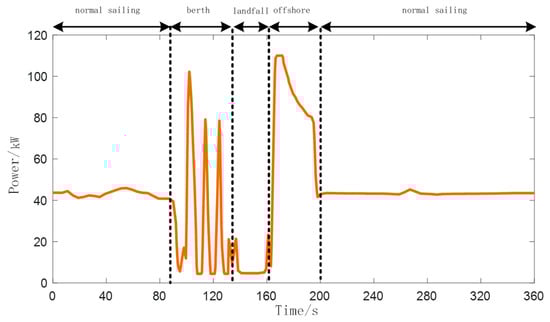
Figure 2.
Vessel operating conditions of Alsterwasser.
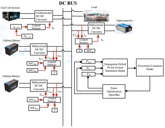
Figure 3.
Architecture of the vessel hybrid power system.
Table 2.
Parameters of Figure 3.
2.2. Hybrid Energy Storage System
An Energy Storage System (ESS) is capable of storing and supplying electrical energy, providing functionalities such as power smoothing, peak shaving and valley filling, as well as voltage and frequency regulation. For new energy vessels, a HESS composed of a lithium battery and supercapacitor is indispensable. Lithium battery systems exhibit superior performance with a typical cycle life of 2000–5000 cycles for marine-grade cells, round-trip charge–discharge efficiency of 90–95%, and operational endurance exceeding 8 years under controlled conditions [2]. These characteristics enable widespread adoption in electric vehicles and marine propulsion systems. Supercapacitors effectively compensate for the limited high-frequency response of lithium batteries, a hybrid configuration successfully demonstrated in fuel cell buses [27], the Alsterwasser passenger vessel [28], and all-electric ferries [29]. Such proven applications underscore its technical viability for maritime operations with highly dynamic load profiles.
2.2.1. Modeling of Lithium Battery
In the field of mathematical modeling for lithium battery, the black-box, electrochemical and equivalent circuit have been the most extensively studied [30]. Among these, the equivalent circuit utilizes electrical components such as resistors, capacitors, and inductors to simulate battery behavior, making it particularly suitable for power system control and simulation studies. This paper adopts the equivalent circuit proposed in [31], as illustrated in Figure 4.
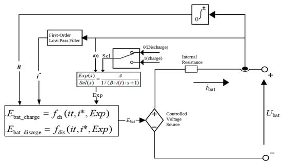
Figure 4.
Equivalent circuit model of the lithium battery.
In the battery model, the voltage polarization term is employed to characterize the influence of the battery’s state on its operational behavior. Furthermore, to enhance the model’s stability and accuracy, a low-pass filter is incorporated, effectively smoothing and regulating the system response, thereby ensuring improved reliability and dynamic performance under varying operating conditions. The governing equations for both charging and discharging processes in the equivalent circuit model of the lithium battery are presented as follows [32]:
where represents the exponential voltage coefficient; represents the exponential capacity coefficient; is the battery constant voltage; represents the polarization resistance; represents the maximum battery capacity; represents the extracted capacity; and represent the low-frequency dynamic current and the battery dynamic current, respectively.
The operational characteristic curves of the lithium battery are presented in Figure 5 and Figure 6.
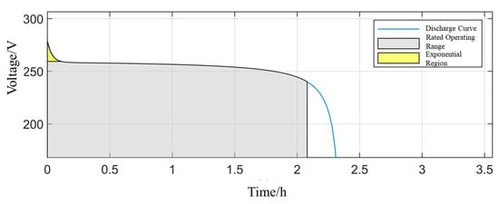
Figure 5.
Discharge curve of the lithium battery at the rated current.
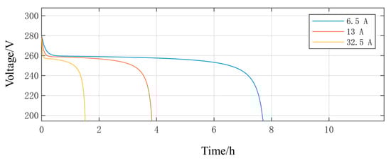
Figure 6.
Constant-current discharge curves of the lithium battery at various current rates.
Figure 5 shows the curve of the terminal voltage of a lithium-ion battery over time during discharge at the rated current. As can be seen from the figure, the voltage gradually decreases from the initial value. The figure marks the “rated operating range” and the “exponential region”, reflecting the battery’s energy release characteristics and voltage decay trend during continuous discharge. Figure 6 shows the curves of the terminal voltage of a lithium-ion battery over time under different discharge currents. It can be seen that the larger the current, the faster the voltage drops. High current discharge can cause the voltage to drop rapidly, affecting the usable capacity and lifespan of the battery. These two figures provide experimental evidence for subsequent energy management strategies and capacity configuration optimization.
2.2.2. Modeling of Supercapacitor
Analogous to the aforementioned lithium battery, the equivalent circuit models are also employed for the supercapacitor. Currently, the five primary types of equivalent circuit for supercapacitor include the nonlinear capacitance, the RC equivalent, the simplified, the three-branch and the transmission line [33]. This paper adopts the equivalent circuit proposed in [34], as illustrated in Figure 7.
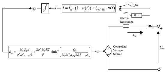
Figure 7.
Equivalent circuit model of the supercapacitor.
The voltage equation for this model is given as follows [35]:
where represents the interfacial area between the electrode and the electrolyte; and represent the dielectric constants of the material and vacuum, respectively; represents the number of electrode layers in the supercapacitor; and represent the number of supercapacitors connected in series and in parallel, respectively; , , and represent the operating temperature, ideal gas constant, Faraday constant, and internal resistance of the supercapacitor, respectively; represents the molecular radius; represents the molar concentration; represents the total charge quantity. It is expressed by the following equation:
2.2.3. Modeling of Fuel Cell
Due to their relatively simple and easily analyzable structure, electrochemical models hold significant application value in the control and optimization research of fuel cell systems. However, the output voltage of fuel cells is susceptible to the pressure generated by H2 and O2 production, as well as external temperature variations. Therefore, based on the electrochemical model and incorporating the laws of energy conservation, momentum conservation, and mass conservation, a hydrogen system model was established. The equivalent circuit model of the fuel cell in this paper is shown in Figure 8 below [36].
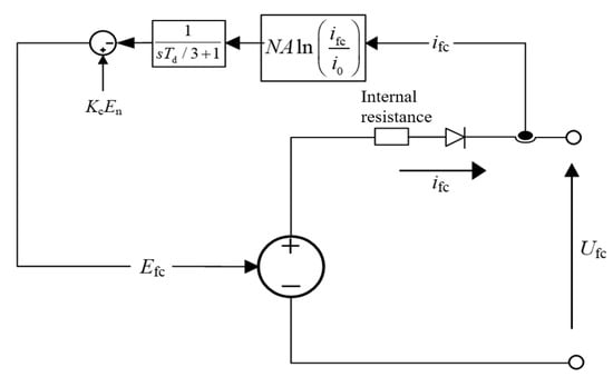
Figure 8.
Equivalent circuit model of the fuel cell.
In practical calculations, it is typically necessary to subtract the corresponding voltage drop from the target voltage to obtain the actual voltage value, as shown in the following equation [37]:
Among these, is the voltage constant under rated operating conditions; is the ohmic polarization voltage; is the Nernst voltage, whose formula is as follows:
where, denotes the ideal gas constant; represents the actual operating temperature of the fuel cell; is Faraday’s constant; is the partial pressure of hydrogen; is the partial pressure of oxygen; is the activation polarization voltage, defined by the following equation:
where denotes the number of cells; represents the fuel cell response time; is the Tafel slope; and denote the fuel cell exchange and output currents, respectively.
3. Improved Droop Control for New Energy Vessels
In the new energy vessel power systems, the fuel cell, lithium battery, and supercapacitor play critical roles. Given their distinct operational characteristics, it is essential to develop tailored control strategies for each component. The well-designed strategies can significantly improve the utilization efficiency of these devices, thereby enhancing the overall system stability. As the primary energy source in the proposed hybrid power system, the fuel cell (FC) converts the chemical energy of hydrogen directly into electricity with high efficiency and zero local emissions [38]. Despite its advantages of high energy density, rapid refueling, and quiet operation, the practical application of FCs in dynamic maritime environments is constrained by several inherent characteristics and operational limits [39]. The dynamic response of a fuel cell is notably slower compared to electrochemical storage devices. The power output cannot follow rapid load transients due to limitations in the electrochemical reaction kinetics, gas supply system (hydrogen and air), and membrane hydration dynamics. The typical power ramp rate for a maritime PEM fuel cell system is in the range of 5–20 kW/s, which is orders of magnitude slower than lithium batteries and supercapacitors [40]. This slow response necessitates the integration of a Hybrid Energy Storage System (HESS) to handle high-frequency power fluctuations, thereby protecting the FC from harmful load cycles and extending its service life.
Therefore, while rationally allocating power and efficiently coordinating the control of energy storage elements, it is crucial to prevent overcharging and over-discharging, enabling them to fully perform their “peak shaving and valley filling” function.
3.1. Power Allocation for HESS Based on Low-Pass Filter
To maximize the performance of HESS, it is essential to rationally allocate power between the lithium battery and the supercapacitor, thereby fully leveraging their respective characteristics. This paper used a power distribution method based on a low-pass filter to address the complex and variable power demand of vessels. The power signal is decomposed into high-frequency and low-frequency components, which are assigned to the supercapacitor and the lithium battery, respectively. This approach not only effectively mitigates load power fluctuations but also extends the service life of the lithium battery. As shown in Figure 9, the vessel’s fluctuating load power is divided into high-frequency and low-frequency components through a low-pass filter. Due to their high-power density, supercapacitors handle the high-frequency components, while the low-frequency components are handled by lithium batteries with high energy density. Because fuel cells have poor dynamic response, large power fluctuations would reduce their lifespan, so the energy management system controls the average power of the fuel cell output based on the operating conditions of the vessel [41].
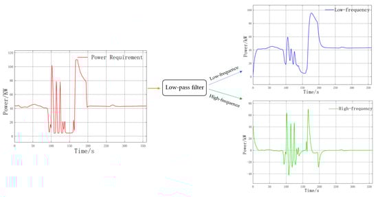
Figure 9.
Schematic diagram of fluctuating power distribution.
3.2. Power Allocation for Lithium Battery Based on Improved Droop Control
3.2.1. Conventional Droop Control
The droop control is one of the most widely used control methods in DC microgrids, as it characterizes the relationship between current and voltage. In this paper, the droop control method is implemented before the DC/DC converter to facilitate regulation. A schematic diagram of the conventional droop control principle is shown in Figure 10.
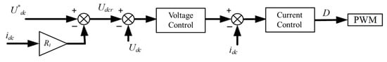
Figure 10.
Schematic diagram of the conventional droop control.
In the diagram, and represent the output voltage and current of the converter, respectively; represents the reference value for the bus voltage; is the actual DC bus voltage.
As shown in this figure, the conventional droop control is a dual-loop control strategy that introduces a virtual resistance prior to the voltage and current loops, aiming to regulate the output current among parallel converters. By incorporating this virtual resistance, current distribution within the system can be effectively adjusted, enabling precise current control and ensuring system stability and performance.
Conventional droop control effectively regulates current sharing among converters; however, the presence of virtual impedance often leads to voltage deviation. The U-I droop characteristic curve is shown in Figure 11.
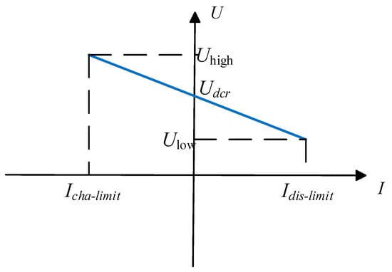
Figure 11.
U-I droop characteristic.
In this figure, U corresponds to in Figure 10, which is the DC bus voltage. and represent the upper and lower limits of the DC bus voltage, respectively; and represent the maximum charging and discharging currents of the energy storage unit, respectively. The curve in the diagram can be expressed as , where is the droop coefficient.
As observed in the figure, when , the energy storage unit initiates discharging and gradually reduces the discharging current to increase the bus voltage until it reaches the reference value. Conversely, when , the energy storage unit starts charging and progressively decreases the charging current to lower until it attains .
The SOC of energy storage elements is primarily measured using the ampere-hour counting method [42], as expressed by the following equation:
In the equation, represents SOC of energy storage unit at time t; represents the initial SOC of energy storage unit i; represents the capacity of energy storage unit i; represents the output current of energy storage unit i.
Differentiating both sides of Equation yields:
Assuming two energy storage units connected in parallel, the ratio of their SOC rates of change is given by the following equation, Where the discharge current is defined as positive, and the charge current is defined as negative.
For the conventional droop control, substituting Equation into yields:
3.2.2. Limitations of Conventional Droop Control
Droop control provides an effective means of regulating converters for system control, though it is subject to certain limitations. Figure 12 illustrates the droop curves with different droop slopes.
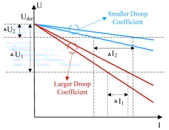
Figure 12.
Droop curves as a function of droop coefficient.
As shown in Figure 12, two units with identical output power and virtual impedance are considered. The current sharing deviation corresponding to the smaller droop coefficient is denoted as , and the voltage deviation from is . For the larger droop coefficient, the current sharing deviation is , and the voltage deviation is . Here, and . This indicates that when a smaller droop coefficient is selected, the voltage deviation from is smaller, but the current sharing deviation becomes larger, thereby reducing current sharing accuracy and output power distribution precision. Conversely, selecting a larger droop coefficient results in a smaller current sharing deviation and higher current sharing accuracy, but leads to a larger voltage deviation from causing a more significant drop in the bus voltage. Therefore, conventional droop control cannot simultaneously meet the requirements of both low voltage deviation and high current sharing accuracy.
Concerning the application of the droop control in power allocation for lithium battery in Equation , the ratio of the SOC change rates between energy storage units depends on their capacities, droop coefficients, and line impedances. Typically, identical droop coefficients and capacities are used, leaving line impedance as the sole factor affecting SOC balancing. However, the line impedances invariably differ, making it difficult to ensure their equality. Consequently, the conventional droop control cannot effectively achieve SOC balancing and must be improved to mitigate the impact of line impedance.
3.2.3. Improved Droop Control Based on SOC Balancing
In the conventional droop control, the droop coefficient remains fixed, and energy storage units distribute current according to this constant ratio. However, when energy storage units have different initial SOC levels, conventional droop control fails to achieve SOC balancing, and current sharing accuracy is compromised. To address this issue, this paper integrates the SOC of the energy storage units with the droop coefficient. As SOC varies, the droop coefficient is adjusted accordingly, thereby enabling SOC balancing and rational current distribution among the units. The improved droop control is expressed as follows:
where indicates the improved droop coefficient and is expressed as follows:
In the equation, represents the initial droop coefficient; represents the dynamic compensation factor.
The design of is critical, as it directly governs the effectiveness of SOC balancing. In this paper, it is formulated as follows:
The design of the dynamic compensation factor in Equation follows two primary principles: first, ensuring the asymptotic stability of the balancing process; second, achieving an adjustable nonlinear response characteristic.
Among them, this term directly compares the SOC of the unit with the average SOC of all units SOC α. It ensures that the compensation is relative and proportional. A unit with an SOC higher than the average will receive a larger during discharge (reducing its current share) and a smaller during charging (increasing its current share), thereby steering its SOC toward the average. This proportional control logic is widely adopted in SOC balancing strategies to prevent excessive current redistribution. During discharge, if 1, reduce the discharge current; if 1, increase the discharge current. During charging, the opposite applies. This can better promote SOC balance and adjust to balance the response speed. The parameter is essentially a gain coefficient. When 0 governs the aggressiveness of the balancing action. A larger increases the sensitivity of to SOC differences, leading to faster balancing but potentially causing overshoot or oscillations. A smaller results in slower, smoother convergence. The exponent adjusts the shape of the SOC difference sensitivity. The parameter is used to adjust the sensitivity curve for SOC differences. When 1, the sensitivity is linear. For 1, small SOC differences near equilibrium are attenuated, while larger differences are emphasized. This helps suppress unnecessary control actions when units are nearly balanced (reducing chattering) while maintaining strong corrective action for significant imbalances. This approach is analogous to using a “dead zone” or nonlinear gain in voltage regulation controllers [43].
This formulation ensures that the droop coefficient adapts autonomously, prioritizing units with lower SOC during discharge and those with higher SOC during charging, thereby achieving inherent SOC equalization without centralized communication. The structure is inspired by and extends the principles of nonlinear adaptive droop control cited in [44], tailored here for the specific dynamics of maritime HESS.
The following derivation is based on two energy storage units connected in parallel.
Using Equations (12) and (13), the principle of SOC balancing is presented as follows:
The difference in SOC between these two energy storage units can be derived from the above equation:
Differentiating both sides of the above equation yields:
Assuming , , and combining Equations and , when , and according to Equations and , respectively. During discharge, the bracketed term becomes negative because is scaled down more heavily than . However, a negative derivative would further decrease the difference, driving the system away from balance. When the unit with lower SOC receives a smaller, which via Equation (12) reduces its effective droop resistance, thereby increasing its discharge current share relative to Battery. This action increases rate of decrease less than , causing the difference to increase towards zero.
Figure 13 illustrates the SOC balancing process. Its core mechanism directly stems from the design of the dynamic compensation factor k in Equations (13) and (14). During charging, cells with lower SOC receive smaller values. According to the droop principle, these cells obtain a larger share of the charging current. This causes cells with higher initial discharge levels to experience faster SOC increases. Conversely, cells with higher SOC receive larger values, reducing their charging current share and slowing their SOC increase. The opposite logic applies during discharge. This autonomous current redistribution mechanism maintains SOC balance within a reasonable range, the dynamic process is shown in Figure 13. This balancing mechanism directly mitigates two critical aging disparities by preventing individual battery cells from remaining in excessively high or low SOC states for extended periods: (1) differing capacity degradation rates accelerated by high voltage in lithium batteries; (2) potential increases in internal resistance and active material loss under low voltage conditions. By equalizing the degradation rates across all cells, the overall usable capacity and power decay of the battery pack are synchronized, thereby extending its effective service life at the system level [45].
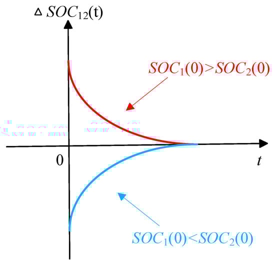
Figure 13.
SOC balancing process.
3.3. Protection Control Strategy for Hybrid Energy Storage Units
During vessel operation, the variability in working conditions leads to significant fluctuations in load power. To stabilize the bus voltage and smooth out power fluctuations, HESS (including lithium battery and supercapacitor) must support high-current discharge operations. However, high-current discharge can cause overcharging or over-discharging of the lithium battery. For lithium battery, continued discharge at low charge levels or continued charging at high levels can easily cause severe damage, negatively impacting their service life. Therefore, designing a protection control strategy for the hybrid energy storage unit is critically important. A well-designed strategy can effectively prevent overcharging and over-discharging of the lithium battery, thereby improving the stability of the entire shipboard system and extending the lifespan of the battery.
3.3.1. SOC Limit Management for Lithium Battery
Lithium batteries are energy storage components with high energy density, and relatively smooth charge–discharge curves. Therefore, under actual operating conditions, a lithium battery should not rapidly reach the SOC limits within a short period, as such scenarios can cause damage to the battery. In practice, the upper SOC limit for lithium batteries is typically set at 80%, and the lower limit at 20% [43]. When the SOC exceeds or falls below these thresholds, the discharge current should be set to zero to ensure safe operation.
3.3.2. SOC Limit Management for Supercapacitor
Compared to the aforementioned energy-type storage components with relatively smooth charge–discharge characteristics, supercapacitors, as power-type devices, feature high power density but low energy density. Consequently, their charge and discharge states can change rapidly, making them prone to reaching the charging and discharging limits of HESS in practical applications. Furthermore, because a supercapacitor is more expensive than a lithium battery, effective SOC limit management is particularly critical. In practice, the upper SOC limit for a supercapacitor is typically 90%, while the lower limit is 10% [46]. To better protect the supercapacitor, this paper divides its SOC into five operational zones: upper charging limit, charging warning, normal operation, discharge warning, and lower discharge limit. Considering that variations in the filter time constant can affect the power distribution within the energy storage system, the filter dynamically adjusts its time constant based on the operational state of the supercapacitor. This ensures that the supercapacitor operates within a safe SOC range. The operational state diagram of the supercapacitor is shown in Figure 14.
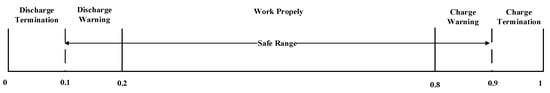
Figure 14.
Operating states of the supercapacitor.
The effectiveness of the SOC limit management strategy hinges on accurate real-time SOC estimation. In this study, the SOC for both lithium battery and supercapacitor is primarily estimated using the ampere-hour counting method, as defined by Equation (8). This method provides a direct and computationally efficient basis for online SOC tracking, aligning with the equivalent circuit models adopted in Section 2.2.
During vessel navigation, the highly variable operating conditions lead to significant fluctuations in load power. The energy storage system must perform charging and discharging operations in real time according to these conditions, making the adjustment of the filter time constant particularly important. Table 3 shows the corresponding adjustments of the filter time constant based on changes in the state of charge of the energy storage system.
Table 3.
The time constant of the filter for the supercapacitor.
The protection strategy actively overrides the primary control signals when SOC limits are approached, ensuring safe operation. This override logic interacts with the improved droop control in Section 3.2 as follows:
For Lithium Batteries: Once the SOC of any battery unit reaches its predefined hard limit (20% or 80%), the protection layer immediately sets its charge/discharge current reference to zero by overriding the droop controller’s output. This disconnects the unit from the DC bus, preventing over-charge/discharge. Concurrently, the improved droop controller dynamically re-allocates the total power demand among the remaining, healthy battery units to maintain system power balance and voltage stability.
For supercapacitors: When the SOC of a supercapacitor enters the warning zone, the protection layer adjusts the time constant of the low-pass filter in the power distribution layer. This limits its charge/discharge rate, restoring the SOC to the normal range. This adjustment occurs seamlessly without affecting droop control functionality, ensuring smooth power delivery and coordinated operation with device protection mechanisms.
Some variables of lithium batteries and supercapacitors, their specific overcharge and over-discharge thresholds, and the specific triggering actions when these limits are reached are defined in Table 4.
Table 4.
Specifics of lithium batteries and supercapacitors.
3.4. Simulation Analysis
Based on the theoretical analysis of the improved droop control presented above, this section conducts a simulation analysis using a system model comprising one fuel cell and three lithium batteries. The relevant model parameters are listed in Table 5. The system performance is compared through simulations using both the conventional and the improved droop control methods.
Table 5.
Parameters for a simulation with droop control.
As shown in the table above, each energy storage unit has a rated capacity of 5 Ah. This uniform capacity configuration enables clearer and faster observation of the balancing effect achieved by the improved droop control. Figure 15 shows the control block diagram of the improved droop control applied to a single energy storage unit.
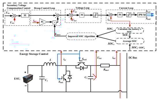
Figure 15.
Energy storage unit improved droop control block diagram.
This paper conducts a simulation analysis of the energy storage equipment under discharge mode, considering two load scenarios: constant load and variable load. Figure 16 shows the comparison of SOC, current, and voltage of the equipment under the constant load condition. The initial SOC values of the three lithium batteries are set to 90%, 85%, and 80%, respectively.
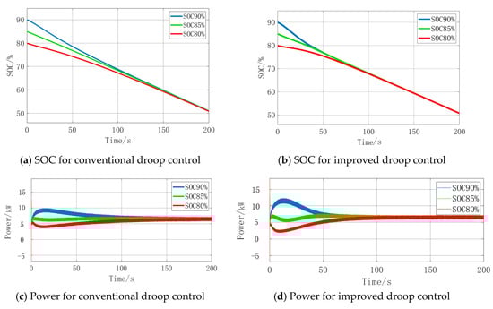
Figure 16.
SOC and power comparisons for constant load.
As shown in the figure above, for the conventional droop control, the system requires approximately 190 s for the convergence of SOC and output power of the three energy storage units. While for the improved droop control, the convergence process is much faster, only 100 s.
Figure 17 provides the performance comparisons for the varying load conditions.
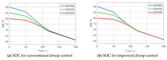
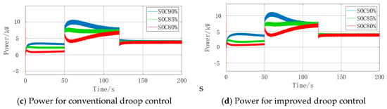
Figure 17.
SOC and power comparisons for varying load.
As observed in Figure 17, although SOC could gradually converge with the conventional droop control, three energy storage units fail to achieve complete SOC balancing within 200 s. In contrast, with the improved droop control, both SOC and output power of all three units converge after approximately 135 s.
All these simulation results indicate that the improved droop control could effectively achieve better SOC balancing performance under different conditions compared with the conventional droop control.
4. Capacity Configuration Optimization for Vessel Hybrid Energy Storage Systems
4.1. Multi-Objective and Multi-Constraint Optimization Configuration Model
The capacity configuration optimization must account for multiple factors, as a single objective or constraint cannot adequately meet the economic requirements of the entire system. Therefore, this paper establishes objectives based on battery degradation, power quality of the DC electrical system, and the cost of the storage devices. The practical operational conditions of the vessel are used to define constraints for the power of the lithium battery and supercapacitor. Subsequently, POA is applied to optimize the capacity configuration of HESS.
The objective of the evaluation function is to ensure the stable operation of all equipment while meeting the requirements for safe and stable navigation of the vessel. The design process of the evaluation function is as follows:
(1) Lithium Battery Degradation Evaluation Function
The frequent and large power fluctuations can directly lead to a shortened lifespan of the lithium battery. Additionally, the battery cost and energy consumption are also considered to enhance the overall economic performance of the system. Therefore, the evaluation function for battery degradation is designed as follows [47]:
where represents the aging cost of the lithium battery; represents its energy consumption cost; represents the output power of the lithium battery; represents its operational cost.
(2) Power Quality of the System
In DC microgrids, the fluctuations in the DC bus voltage serve as a key indicator of power quality. The power quality evaluation function in this paper is formulated as follows [48]:
where represents the DC bus voltage at time .
(3) Supercapacitor Degradation Evaluation Function
Like a lithium battery, the aging, energy consumption, output power, and operational costs of a supercapacitor also significantly affect the economic performance of the vessel’s hybrid power system. The evaluation function is formulated as follows [49]:
where represents the aging cost of the supercapacitor; represents its energy consumption cost; represents the output power of the supercapacitor at time t; represents its operational cost.
(4) System Cost Function
where, and represent the numbers of lithium batteries and supercapacitors, respectively; and represent the unit prices of lithium batteries and supercapacitors, respectively.
Based on the aforementioned evaluation functions, the objective function for the vessel power system can be obtained:
The aforementioned objective function incorporates several factors: the lifecycles of lithium batteries and supercapacitors, fluctuations in the bus voltage, and system cost. The weighting factors a, b, and d in Equation are determined through a combination of expert judgment and sensitivity analysis, which is a common approach in multi-objective optimization of Hybrid Energy Storage Systems (HESS) [50]. Lithium batteries are the main energy storage units, and their aging rate directly determines the long-term operating costs and replacement frequency of the system, so the weight is given the highest priority. Supercapacitors are responsible for managing high-frequency power fluctuations and protecting fuel cells and lithium batteries. Therefore, their cost must be considered in the optimization objectives and assigned a certain weight. Power quality can be better achieved through the coordination of the first two, this paper assigns the corresponding weights a, b, and d as 0.5, 0.3, and 0.2, respectively. This weighting scheme aligns with prior HESS studies that prioritize battery degradation and system cost while ensuring operational stability [51]. A sensitivity analysis was conducted to verify that the selected weights do not lead to significant performance trade-offs in the optimized system. When constructing the objective function of Equation , each cost and performance metric is first normalized using a reference benchmark value to ensure numerical comparability. These benchmark values are selected based on the system’s design requirements.
After establishing the evaluation functions above, the variables in the system must be subjected to the following constraints:
In these constraints, the first equality ensures stable vessel operation by maintaining power balance. The next three equations, meanwhile, are instituted to confine the output power of each unit within its permissible range. This prevents potential damage from over- or under-powering the equipment, which is critical for the vessel’s operational safety.
4.2. Parrot Optimization Algorithm
The POA is an efficient metaheuristic algorithm inspired by the behaviors of domesticated Green-cheeked Conures (Pyrrhura Molinae parrots), including foraging, perching, communication, and fear responses towards strangers. These behaviors are abstracted into four distinct mathematical formulations to guide the search for optimal solutions. Unlike traditional metaheuristics, which are characterized by explicit exploration and exploitation phases, the POA allows each agent to randomly adopt one of four behaviors during every iteration. This approach accurately mimics the random behavior of parrots during domestication, significantly improving population diversity. Consequently, the POA effectively reduces the risk of becoming trapped in local optima [24].
(1) Population Initialization
represents the population size and represent the maximum number of iterations. The search is constrained within the upper bound and the lower bound . The population initialization formula of POA is presented in the following expression:
where represents a random number within the range , and represents the initial position of the parrot.
(2) Foraging Behavior
During the foraging behavior, a parrot estimates the approximate location of food primarily by observing the positions of either the food source or its owner, and subsequently moves toward this estimated position. The mathematical representation for this foraging movement is given as follows:
where represents the current position of the parrot, while represents its updated position in the subsequent iteration; represents the mean position of the current population; corresponds to a distribution, which models the flight pattern of the parrot; represents the best position found from the initialization up to the current iteration, analogous to the current location of the owner; indicates the current iteration number.
The component represents the movement based on the parrot’s relative position to its owner. Meanwhile, the term reflects the behavior of observing the collective position of the entire flock to further refine the direction towards the estimated food location.
The mean position of the current population is defined as follows:
The distribution can be generated following the standard procedure given in the formula below, while :
(3) Perching Behavior
In this model, perching behavior is defined as the action where a parrot spontaneously flies to a random part of its owner’s body and remains motionless for a certain duration. The mathematical representation of this process is given below:
where, denotes a row vector of ones with a dimension of ; the term simulates the process of flying toward the owner; represents the action of randomly alighting on a specific part of the owner’s body.
(4) Communicative Behavior
Parrots are fundamentally social, engaging in frequent communication within a flock. This behavior includes signaling the intent to fly toward or away from the group. For POA, it is postulated that both behaviors are equally likely. The central position of the flock is represented by the mean position of the current population. This entire process is formulated as follows:
In this formulation, the term represents the process where an individual joins the flock for communication. Conversely, the term represents the process of immediately flying away after an interaction. These two mutually exclusive behaviors are triggered by a randomly generated value.
(5) Fear of Strangers
It is common for birds to show an instinctive fear of strangers, a trait also observed in parrots. In the algorithm, their tendency to keep away from unfamiliar entities and to move towards safer locations alongside their owner is encoded as follows:
In this formulation, the term represents the process of reorienting and flying toward the owner. Conversely, the term represents the evasive action of moving away from a stranger.
4.3. Capacity Configuration Optimization of Hybrid Energy Storage System
The POA is employed to jointly optimize the power output of the lithium battery and supercapacitor within HESS, along with the DC bus voltage. Figure 18 just illustrates the specific optimization procedure of POA. The best fitness value of POA is shown in Figure 19.
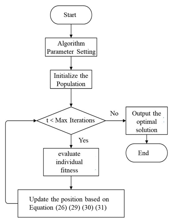
Figure 18.
Flowchart of POA.
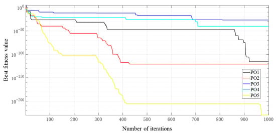
Figure 19.
Convergence curve of POA.S.
Given that the parrot exhibits four distinct behaviors, varying the proportional weight assigned to each leads to differences in the final convergence curve. In this section, five conditions are discussed: POA1, POA2, POA3, POA4 and POA5 correspond to the ratio of the four behaviors 1:1:1:1, 2:1:1:1, 1:2:1:1, 1:1:2:1 and 1:1:1:2, respectively. To rigorously evaluate and compare the optimization performance of POA under different behavioral weights (POA1 to POA5), a structured evaluation procedure was implemented, encompassing defined metrics, multiple independent runs, and statistical analysis. This paper presents the minimum value of the objective function achieved at algorithm termination. Independent optimization runs were conducted for each of the five POA configurations (POA1-POA5). Each run was initialized with a different random seed to ensure statistical independence. The universal algorithm parameters were population size of 50, maximum iterations set to 200, with all other conditions kept consistent across runs. Data collected from 50 runs was compared across each POA configuration. Since the objective is to minimize a comprehensive cost function, a lower fitness value indicates a better solution. From the convergence shown in the above figure, POA5 presents the best performance, which means the optimization effect is better if the fourth behavior has a higher weight. In other words, the effect is optimal when the behavioral weight assigned to fear of strangers is highest. The convergence curve shown in Figure 18 illustrates a representative single run of the best-performing POA5 configuration.
Based on the objectives and constraints above, the POA is employed for the search process; the parameter data involved is shown in Table 6. The final optimal solution derived from this process is presented in Table 7. Furthermore, the following figure illustrates a comparison of the power output for the lithium battery and supercapacitor before and after optimization.
Table 6.
Parameter data.
Table 7.
Capacity optimization results.
As shown in Table 8, after optimization, the peak power of the lithium battery decreases from 61 kW to 50 kW, a reduction of 18%, indicating a more stable power output, and after optimization, the supercapacitor takes on more high-frequency fluctuation power, with its peak power rising from 50 kW to 61 kW, which helps extend its lifespan.
Table 8.
Key figure comparison.
As shown in Figure 20, the vessel’s load fluctuates most frequently between 100 and 150 s. Such significant power variations can damage the lithium battery and degrade its service life. The evaluation function in this paper comprehensively considers the energy consumption and lifecycle of the lithium battery. Based on the POA, the power profile is effectively reshaped. The optimized profile shows a marked reduction in peak battery power demand, particularly during the high-fluctuation period (100–150 s). Between 150–200 s, although a higher power peak occurs, its rate of increase is relatively gradual, which is inherently less damaging to the equipment. Nevertheless, the optimization algorithm, by holistically balancing all objective terms, also reduces the peak magnitude within this interval.
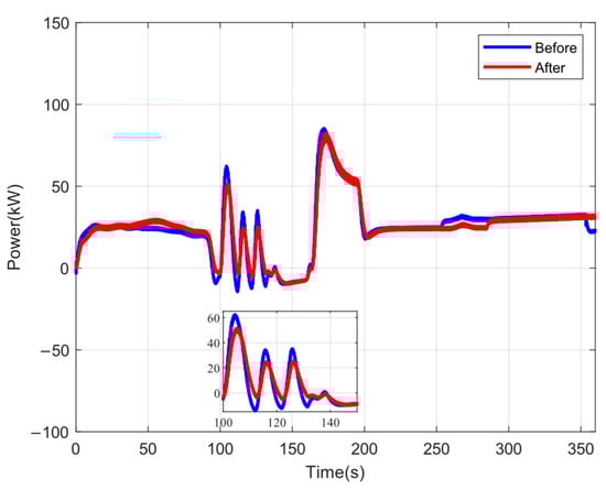
Figure 20.
The power of the lithium battery before and after optimization.
Figure 21 compares the supercapacitor power output before and after optimization. As with the lithium battery, the evaluation function also accounts for the wear and lifespan of the supercapacitor. The supercapacitor is tasked with handling high-frequency power fluctuations due to its rapid charging and discharging, which are crucial during 100–150 s. However, given its high cost, the optimization algorithm, guided by the aforementioned evaluation function, determines the final power allocation for the supercapacitor as shown.
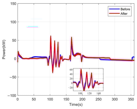
Figure 21.
The power of the supercapacitor before and after optimization.
As shown in Figure 22, load fluctuations are most frequent between 100 and 150 s. After optimization, the peak power of the lithium battery is reduced (from 61 kW to 50 kW), and the fluctuation amplitude decreases; the peak power of the supercapacitor increases (from 50 kW to 61 kW), effectively handling high-frequency fluctuations. The fuel cell power remains stable. This shows that in the optimized hybrid power system of the new energy vessel, every device can effectively handle complex and variable power demands, ultimately ensuring the vessel’s power requirements while significantly improving the overall system’s economic efficiency and equipment lifespan.
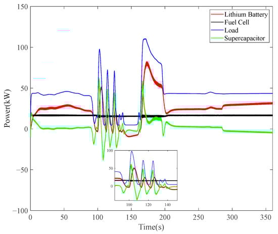
Figure 22.
The power of every device after optimization.
Table 9 shows a comparison of relevant parameters of lithium batteries and supercapacitors before and after optimization, including SOC balancing speed, power fluctuation reduction, and lifespan loss. It can be seen that the power fluctuation of the lithium battery decreased by 18%, while that of the supercapacitor increased by 18%. The lifespan loss of both the lithium battery and the supercapacitor significantly improved, increasing by 12.6% and 19.0%, respectively, which also validates the superiority of the results. To precisely evaluate the reshaping effect of optimization strategies on system dynamic behavior, this section extracts specialized quantitative metrics for the high-fluctuation transient interval (100–150 s) shown in Figure 22, as presented in Table 10. Analysis indicates that the combined effect of POA-based optimization allocation and the improved droop control strategy achieves redistribution of dynamic power demand.
Table 9.
Quantitative comparison before and after optimization.
Table 10.
Quantitative Analysis of Dynamic Power Characteristics Based on Transient Intervals.
5. Conclusions
To facilitate the maritime industry’s transition toward low-carbon operations, this paper presents a comprehensive framework for hybrid energy storage management in fuel cell-powered vessels, validated through the Alsterwasser case study. The proposed integrated strategy yields quantifiable improvements across three critical dimensions:
(1) Enhanced Dynamic Response and SOC Balancing via Adaptive Droop Control:
By replacing the fixed droop coefficient with an SOC-sensitive adaptive coefficient, the improved droop control achieves autonomous state-of-charge equalization while maintaining high current-sharing accuracy. This method directly reduces the SOC convergence time from 190 s to 100 s under constant load and from over 200 s to 135 s under variable load, enabling faster and more robust energy management without additional communication links.
(2) Robust Operation through Intelligent Protection and Adaptive Filtering:
The dynamic SOC-limit management and filter-time-constant adjustment prevent over-charging/discharging of lithium-battery and supercapacitor units. This protection strategy, integrated with the power-split method based on a low-pass filter, extends the cycle life of storage devices and enhances system reliability during highly variable vessel operations, as evidenced by the stable DC-bus voltage and safe SOC ranges shown in the simulations.
(3) Economically Optimal Capacity Allocation via Parrot Optimization Algorithm:
A multi-objective POA-based capacity configuration model jointly minimizes battery degradation, supercapacitor degradation, DC-bus voltage fluctuation, and system cost under realistic operational constraints. The POA-driven optimization reduces the lithium-battery peak power by 18% (from 61 kW to 50 kW) while increasing the supercapacitor peak power by 18% (from 50 kW to 61 kW). This power-profile reshaping shifts high-frequency dynamics to the more cycle-resilient supercapacitor, thereby lowering lifecycle costs and improving the economic feasibility of the hybrid storage system.
The core objective of this paper is to maintain fuel cells in a state of consistently efficient and enduring operation. Given the inherent slow dynamic characteristics of fuel cells, the enhanced droop control synergizes with capacity allocation based on a power-optimized architecture to ensure the fuel cell primarily addresses the low-frequency steady-state portion of load demand. As shown in Figure 21, even during high-transient intervals (e.g., 100–150 s), the fuel cell power curve exhibits remarkable stability, with the HESS system actively compensating for rapid load fluctuations. This approach not only prevents excessive stress on the fuel cell stack, thereby extending its lifespan, but also enables operation near its optimal efficiency point. Consequently, this strategy does not alter the fuel cell’s inherent response characteristics; instead, it constructs a system-level environment that mitigates the impact of its dynamic limitations, fulfilling the original intent of adopting a hybrid energy storage solution.
While the proposed framework demonstrates significant improvements, several aspects warrant further investigation. The current study assumes an ideal fuel cell hydrogen supply and does not model performance degradation over time. Future research should address these limitations by integrating fuel cell aging models, developing hybrid POA-model predictive control for adaptive reconfiguration, applying machine learning for improved SOC estimation, and conducting experimental validation to confirm simulation results.
Author Contributions
Conceptualization, X.X. and W.S.; methodology, H.C.; software, X.X.; validation, X.X., W.S. and H.C.; formal analysis, N.G.; investigation, Y.Y.; resources, A.S.; data curation, W.S.; writing—original draft preparation, M.B.; writing—review and editing, M.B.; visualization, A.S.; supervision, X.X.; project administration, H.C.; All authors have read and agreed to the published version of the manuscript.
Funding
This research received no external funding.
Data Availability Statement
The data presented in this study are available on request from the corresponding author.
Conflicts of Interest
The authors declare no conflict of interest.
References
- Nawaz, F.; Pashajavid, E.; Fan, Y.; Batool, M. Enhanced Distributed Coordinated Control Strategy for DC Microgrid Hybrid Energy Storage Systems Using Adaptive Event Triggering. Electronics 2025, 14, 3303. [Google Scholar] [CrossRef]
- Li, J.; Li, Y.; Liu, H.; Lyu, C.; Yang, H.; Ma, S. Research on Application Technology of Lithium Battery Assessment Technology in Energy Storage System. Energy Rep. 2023, 9, 1003–1013. [Google Scholar] [CrossRef]
- Kolodziejski, M.; Michalska-Pozoga, I. Battery Energy Storage Systems in Ships’ Hybrid/Electric Propulsion Systems. Energies 2023, 16, 1122. [Google Scholar] [CrossRef]
- Guo, X.; Lang, X.; Yuan, Y.; Tong, L.; Shen, B.; Long, T.; Mao, W. Energy Management System for Hybrid Ship: Status and Perspectives. Ocean Eng. 2024, 310, 118638. [Google Scholar] [CrossRef]
- Gong, T.; Gao, F.; Liu, W. An Improved Feedforward Control Strategy in Droop-Controlled DC Microgrids for the More Electric Aircraft. In Proceedings of the 2025 IEEE 16th International Symposium on Power Electronics for Distributed Generation Systems (PEDG), Nanjing, China, 22–25 June 2025; IEEE: New York, NY, USA, 2025; pp. 499–503. [Google Scholar]
- Liu, Y.; Deng, W.; Yang, P.; Teng, Y.; Zhang, X.; Yang, Y.; Pei, W. Dispatchable Droop Control Strategy for DC Microgrid. Energy Rep. 2023, 9, 98–102. [Google Scholar] [CrossRef]
- Wang, X.; Wang, H. Improved Droop Control Strategy of Multiple Energy Storage Applications in an AC Microgrid Based on the State of Charge. Electronics 2021, 10, 1726. [Google Scholar] [CrossRef]
- Firmansyah, R.; Ramli, M.A.M. A New Adaptive Droop Control Strategy for Improved Power Sharing Accuracy and Voltage Restoration in a DC Microgrid. Ain Shams Eng. J. 2024, 15, 102899. [Google Scholar] [CrossRef]
- Zhengwan, D.; Ningyu, G.; Yali, Z. Improved Droop Control Strategy for Distributed Photovoltaic Power Generation Systems. Front. Energy Res. 2024, 12, 1430580. [Google Scholar] [CrossRef]
- Kulkarni, S.V.; Gaonkar, D.N. Improved Droop Control Strategy for Parallel Connected Power Electronic Converter Based Distributed Generation Sources in an Islanded Microgrid. Electr. Power Syst. Res. 2021, 201, 107531. [Google Scholar] [CrossRef]
- Mohammadi, F.; Nazri, G.-A.; Saif, M. An Improved Droop-Based Control Strategy for MT-HVDC Systems. Electronics 2020, 9, 87. [Google Scholar] [CrossRef]
- Lu, X.; Guerrero, J.M.; Sun, K.; Vasquez, J.C. An Improved Droop Control Method for DC Microgrids Based on Low Bandwidth Communication with DC Bus Voltage Restoration and Enhanced Current Sharing Accuracy. IEEE Trans. Power Electron. 2014, 29, 1800–1812. [Google Scholar] [CrossRef]
- Tian, G.; Zheng, Y.; Liu, G.; Zhang, J. SOC Balancing and Coordinated Control Based on Adaptive Droop Coefficient Algorithm for Energy Storage Units in DC Microgrid. Energies 2022, 15, 2943. [Google Scholar] [CrossRef]
- Kannayeram, G.; Prakash, N.B.; Muniraj, R. Intelligent Hybrid Controller for Power Flow Management of PV/Battery/FC/SC System in Smart Grid Applications. Int. J. Hydrogen Energy 2020, 45, 21779–21795. [Google Scholar] [CrossRef]
- Lucia, U. Overview on Fuel Cells. Renew. Sustain. Energy Rev. 2014, 30, 164–169. [Google Scholar] [CrossRef]
- Libich, J.; Máca, J.; Vondrák, J.; Čech, O.; Sedlaříková, M. Supercapacitors: Properties and Applications. J. Energy Storage 2018, 17, 224–227. [Google Scholar] [CrossRef]
- Cheng, S.; Sun, W.-B.; Liu, W.-L. Multi-Objective Configuration Optimization of a Hybrid Energy Storage System. Appl. Sci. 2017, 7, 163. [Google Scholar] [CrossRef]
- Li, Y.; Liu, X.; Zhao, Y.; He, T.; Zeng, H. Optimization Design of Hybrid Energy Storage Capacity Configuration for Electric Ship. Energy Rep. 2024, 11, 887–894. [Google Scholar] [CrossRef]
- Jing, F.; Wang, X.; Zhang, Y.; Chang, S. A Capacity Optimization Method of Ship Integrated Power System Based on Comprehensive Scenario Planning: Considering the Hydrogen Energy Storage System and Supercapacitor. Energies 2025, 18, 5305. [Google Scholar] [CrossRef]
- Huang, J.; An, Q.; Zhou, M.; Tang, R.; Dong, Z.; Lai, J.; Li, X.; Yang, X. A Self-Adaptive Joint Optimization Framework for Marine Hybrid Energy Storage System Design Considering Load Fluctuation Characteristics. Appl. Energy 2024, 361, 122973. [Google Scholar] [CrossRef]
- Zhang, Y.; Yuan, C.; Du, X.; Chen, T.; Hu, Q.; Wang, Z.; Lu, J. Capacity Configuration of Hybrid Energy Storage System for Ocean Renewables. J. Energy Storage 2025, 116, 116090. [Google Scholar] [CrossRef]
- Barrera-Cardenas, R.A.; D’Arco, S.; Piegari, L.; Tricoli, P. Pareto-Based Design Optimisation of Hybrid Energy Storage Systems for Full-Electric Vessels. IET Power Electron. 2025, 18, e70027. [Google Scholar] [CrossRef]
- Li, X.; Pan, L.; Zhang, J.; Jin, Z.; Jiang, W.; Wang, Y.; Liu, L.; Tang, R.; Lai, J.; Yang, X.; et al. A Novel Capacity Allocation Method for Hybrid Energy Storage System for Electric Ship Considering Life Cycle Cost. J. Energy Storage 2025, 116, 116070. [Google Scholar] [CrossRef]
- Lian, J.; Hui, G.; Ma, L.; Zhu, T.; Wu, X.; Heidari, A.A.; Chen, Y.; Chen, H. Parrot Optimizer: Algorithm and Applications to Medical Problems. Comput. Biol. Med. 2024, 172, 108064. [Google Scholar] [CrossRef]
- Qawaqneh, H.; Sayyed, O.; Alomari, K.; Gulnara, B.; Smerat, A.; Montazeri, Z.; Dehghani, M.; Parkash, O.; Eguchi, K. Pipefish Optimization Algorithm (POA): A Nature-Inspired Metaheuristic for Robust and Adaptive Global Optimization. Int. J. Intell. Eng. Syst. 2025, 18, 2025. [Google Scholar]
- Bassam, A.M.; Phillips, A.B.; Turnock, S.R.; Wilson, P.A. An Improved Energy Management Strategy for a Hybrid Fuel Cell/Battery Passenger Vessel. Int. J. Hydrogen Energy 2016, 41, 22453–22464. [Google Scholar] [CrossRef]
- Hu, X.; Johannesson, L.; Murgovski, N.; Egardt, B. Longevity-Conscious Dimensioning and Power Management of the Hybrid Energy Storage System in a Fuel Cell Hybrid Electric Bus. Appl. Energy 2015, 137, 913–924. [Google Scholar] [CrossRef]
- Khaligh, A.; Li, Z. Battery, Ultracapacitor, Fuel Cell, and Hybrid Energy Storage Systems for Electric, Hybrid Electric, Fuel Cell, and Plug-In Hybrid Electric Vehicles: State of the Art. IEEE Trans. Veh. Technol. 2010, 59, 2806–2814. [Google Scholar] [CrossRef]
- Al-Falahi, M.D.A.; Jayasinghe, S.D.G.; Enshaei, H. Hybrid Algorithm for Optimal Operation of Hybrid Energy Systems in Electric Ferries. Energy 2019, 187, 115923. [Google Scholar] [CrossRef]
- Jung, S. Mathematical Model of Lithium-Ion Batteries with Blended-Electrode System. J. Power Sources 2014, 264, 184–194. [Google Scholar] [CrossRef]
- Nejad, S.; Gladwin, D.T.; Stone, D.A. A Systematic Review of Lumped-Parameter Equivalent Circuit Models for Real-Time Estimation of Lithium-Ion Battery States. J. Power Sources 2016, 316, 183–196. [Google Scholar] [CrossRef]
- Tremblay, O.; Dessaint, L.-A.; Dekkiche, A.I. A Generic Battery Model for the Dynamic Simulation of Hybrid Electric Vehicles. In Proceedings of the 2007 IEEE Vehicle Power and Propulsion Conference, Arlington, TX, USA, 9–12 September 2007; pp. 284–289. [Google Scholar]
- Zucca, M.; Hassanzadeh, M.; Conti, O.; Pogliano, U. Accurate Parameters Identification of a Supercapacitor Three-Branch Model. IEEE Access 2023, 11, 122387–122398. [Google Scholar] [CrossRef]
- Oldham, K.B. A Gouy–Chapman–Stern Model of the Double Layer at a (Metal)/(Ionic Liquid) Interface. J. Electroanal. Chem. 2008, 613, 131–138. [Google Scholar] [CrossRef]
- Volfkovich, Y.M. Electric Double Layer Capacitors: A Review. Russ. J. Electrochem. 2024, 60, 761–794. [Google Scholar] [CrossRef]
- Spiegel, C. Chapter 3—Fuel Cell Electrochemistry. In PEM Fuel Cell Modeling and Simulation Using Matlab; Spiegel, C., Ed.; Academic Press: Burlington, ON, Canada, 2008; pp. 49–76. [Google Scholar]
- Liu, Y.; Liu, J.; Zhang, Y.; Wu, Y.; Chen, Z.; Ye, M. Rule Learning Based Energy Management Strategy of Fuel Cell Hybrid Vehicles Considering Multi-Objective Optimization. Energy 2020, 207, 118212. [Google Scholar] [CrossRef]
- Staffell, I.; Scamman, D.; Velazquez Abad, A.; Balcombe, P.; Dodds, P.E.; Ekins, P.; Shah, N.; Ward, K.R. The Role of Hydrogen and Fuel Cells in the Global Energy System. Energy Environ. Sci. 2019, 12, 463–491. [Google Scholar] [CrossRef]
- Elkafas, A.G.; Rivarolo, M.; Gadducci, E.; Magistri, L.; Massardo, A.F. Fuel Cell Systems for Maritime: A Review of Research Development, Commercial Products, Applications, and Perspectives. Processes 2022, 11, 97. [Google Scholar] [CrossRef]
- Fu, Z.; Lu, L.; Zhang, C.; Xu, Q.; Zhang, X.; Gao, Z.; Li, J. Fuel Cell and Hydrogen in Maritime Application: A Review on Aspects of Technology, Cost and Regulations. Sustain. Energy Technol. Assess. 2023, 57, 103181. [Google Scholar] [CrossRef]
- Pan, R.; Yang, D.; Wang, Y.; Chen, Z. Health Degradation Assessment of Proton Exchange Membrane Fuel Cell Based on an Analytical Equivalent Circuit Model. Energy 2020, 207, 118185. [Google Scholar] [CrossRef]
- Hannan, M.A.; Hoque, M.M.; Hussain, A.; Yusof, Y.; Ker, P.J. State-of-the-Art and Energy Management System of Lithium-Ion Batteries in Electric Vehicle Applications: Issues and Recommendations. IEEE Access 2018, 6, 19362–19378. [Google Scholar] [CrossRef]
- Simpson-Porco, J.W.; Shafiee, Q.; Dörfler, F.; Vasquez, J.C.; Guerrero, J.M.; Bullo, F. Secondary Frequency and Voltage Control of Islanded Microgrids via Distributed Averaging. IEEE Trans. Ind. Electron. 2015, 62, 7025–7038. [Google Scholar] [CrossRef]
- Mohamed, Y.A.-R.I.; El-Saadany, E.F. Adaptive Decentralized Droop Controller to Preserve Power Sharing Stability of Paralleled Inverters in Distributed Generation Microgrids. IEEE Trans. Power Electron. 2008, 23, 2806–2816. [Google Scholar] [CrossRef]
- Baronti, F.; Fantechi, G.; Leonardi, E.; Roncella, R.; Saletti, R. Hierarchical Platform for Monitoring, Managing and Charge Balancing of LiPo Batteries. In Proceedings of the 2011 IEEE Vehicle Power and Propulsion Conference, Chicago, IL, USA, 6–9 September 2011; pp. 1–6. [Google Scholar]
- Li, T.; Huang, L.; Liu, H. Energy Management and Economic Analysis for a Fuel Cell Supercapacitor Excavator. Energy 2019, 172, 840–851. [Google Scholar] [CrossRef]
- Xu, B.; Oudalov, A.; Ulbig, A.; Andersson, G.; Kirschen, D.S. Modeling of Lithium-Ion Battery Degradation for Cell Life Assessment. IEEE Trans. Smart Grid 2018, 9, 1131–1140. [Google Scholar] [CrossRef]
- Barros, J.; De Apráiz, M.; Diego, R.I. Power Quality in DC Distribution Networks. Energies 2019, 12, 848. [Google Scholar] [CrossRef]
- Lim, K.J.; Chong, L.W.; Morris, S.; Lim, B.H.; Fahmi, M.; Palanichamy, C. Battery Lifetime and Life Cycle Cost Analysis of Battery-Supercapacitor Hybrid Energy Storage System for Standalone Power System. In Proceedings of the 2022 IEEE 5th International Symposium in Robotics and Manufacturing Automation (ROMA), Malacca, Malaysia, 6–8 August 2022; pp. 1–6. [Google Scholar]
- Rasool, M.H.; Taylan, O.; Perwez, U.; Batunlu, C. Comparative Assessment of Multi-Objective Optimization of Hybrid Energy Storage System Considering Grid Balancing. Renew. Energy 2023, 216, 119107. [Google Scholar] [CrossRef]
- Hu, X.; Xu, L.; Lin, X.; Pecht, M. Battery Lifetime Prognostics. Joule 2020, 4, 310–346. [Google Scholar] [CrossRef]
Disclaimer/Publisher’s Note: The statements, opinions and data contained in all publications are solely those of the individual author(s) and contributor(s) and not of MDPI and/or the editor(s). MDPI and/or the editor(s) disclaim responsibility for any injury to people or property resulting from any ideas, methods, instructions or products referred to in the content. |
© 2025 by the authors. Licensee MDPI, Basel, Switzerland. This article is an open access article distributed under the terms and conditions of the Creative Commons Attribution (CC BY) license.