Abstract
This paper addresses the trajectory tracking problem for a six-degree-of-freedom (6-DOF) underwater manipulator subject to complex disturbances and input saturation. It proposes a fixed-time preset performance sliding mode control method considering input saturation (FT-PP-SMC-IS), aiming to achieve rapid and stable tracking performance under these constraints. Firstly, to improve modeling accuracy, the Newton–Euler method and Morison’s equation are integrated to establish a more precise dynamic model of the underwater manipulator. Secondly, to balance dynamic and steady-state performance, a preset performance function is designed to constrain the tracking error boundaries. Based on dual-limit homogeneous theory, a fixed-time sliding mode surface is constructed, significantly enhancing the convergence speed and fixed-time stability. Furthermore, to suppress the effects of input saturation, a fixed-time auxiliary system is designed to compensate in real-time for deviations caused by actuator saturation. By separately constructing the sliding mode reaching law and equivalent control law, global fixed-time convergence of the system states is ensured. Based on Lyapunov stability theory, the fixed-time stability of the closed-loop system is rigorously proven. Finally, comparative simulation experiments verify the effectiveness and superiority of the proposed method.
1. Introduction
The ocean covers approximately 71% of the Earth’s surface and contains abundant biological resources, mineral resources, energy resources, and spatial resources, serving as a treasure trove of resources essential for human survival. Entering the 21st century, the pace of human exploration of the ocean has accelerated significantly, leading to increasingly higher demands for underwater intelligent equipment. Manipulators, owing to their capability to perform diverse tasks, are considered the most suitable tools for underwater operations [1,2,3]. However, underwater manipulator systems are complex nonlinear systems and are subject to influences from the aquatic environment and unknown disturbances, posing significant challenges to high-precision trajectory tracking control [4]. Therefore, the research presented in this paper holds substantial theoretical and practical significance.
In recent years, scholars from various countries have conducted extensive and in-depth research on the control of underwater manipulators. Sliding mode control has been widely applied in industrial control due to its fast convergence and strong robustness to uncertain disturbances [5,6]. Essentially, sliding mode control consists of two phases: the reaching phase and the sliding phase. The control objective in the reaching phase is to drive the system from its initial state to the sliding surface, with the design focus on formulating a reaching control law to ensure finite-time convergence. The control objective in the sliding phase is to maintain the system on the sliding surface and slide it toward the equilibrium point, with the design emphasis on constructing a sliding surface to achieve desirable dynamic performance [7]. However, the inherent characteristics of sliding mode control also pose challenges for controller design, such as how to mitigate chattering and how to achieve finite-time convergence. Jingming Xu et al. proposed a novel control scheme combining implicit robust tube model predictive control with adaptive sliding mode control to address the trajectory tracking problem for underwater manipulators under model uncertainties and external disturbances. This method enhances computational efficiency and control precision through innovative design, and its effectiveness has been validated via simulation and experimental studies [8]. To address the trajectory tracking control challenges faced by underwater manipulators under hydrodynamic effects and sealing friction, Mingquan Zhang et al. proposed an adaptive fuzzy sliding mode control (AFSMC) strategy. This method utilizes a fuzzy system to estimate disturbances online and adaptively adjust control parameters, achieving high-precision and highly robust trajectory tracking while effectively suppressing the chattering phenomenon inherent in traditional sliding mode control [9]. To address the trajectory tracking control challenge for underwater manipulators in wave-disturbed environments, Dahui Ge et al. developed a wave dynamic model and designed a sliding mode controller, achieving fast and precise tracking of desired trajectories under time-varying wave forces. This validates the effectiveness and superiority of the proposed control strategy in marine conditions [10]. Yuguang Zhong et al. addressed the challenges of high-precision trajectory tracking and chattering suppression for multi-joint underwater manipulators in complex hydrodynamic environments by proposing a dynamic modeling approach based on the Lagrange–Morison formulation and an improved adaptive fuzzy sliding mode control method. This solution enables faster convergence speed and higher control precision compared to traditional algorithms [11]. Minghao Liu et al. addressed the high-precision control challenges for manipulators mounted on underwater vehicles caused by model uncertainties and flow disturbances. They proposed a sliding mode control method integrating time delay estimation with a specific reaching law, which achieves effective disturbance suppression, eliminates chattering, and ensures precise trajectory tracking without requiring an accurate dynamic model [12]. Pengbing Zhao et al. addressed the issues of parameter perturbations and vibration disturbances in manipulator systems installed on moving bases by proposing a variable-gain integral sliding mode control strategy. This approach enables the system to maintain global stability while exhibiting strong robustness to disturbances and possessing self-adaptive adjustment capabilities for controller parameters [13].
While the aforementioned studies primarily focus on suppressing chattering in sliding mode control and achieving high-precision trajectory tracking, the issue of convergence time remains an inevitable challenge in sliding mode control. In response, a non-singular terminal sliding mode control method has been proposed, enabling the system to achieve faster fixed-time convergence performance while avoiding singularities [14]. This approach remedies the limitations of classical methods in terms of convergence time and precision. Hui Huang et al. proposed an adaptive non-singular fixed-time sliding mode control scheme based on a higher-order sliding mode observer to address trajectory tracking and vibration suppression for underwater flexible manipulators mounted on moving bases. This method achieves enhanced disturbance rejection and active vibration suppression capabilities [15]. Zaare, Saeed et al. addressed the position tracking control problem for underwater vehicle manipulators under model uncertainties and sensor constraints by proposing a predefined-time non-singular terminal sliding mode control method integrated with a finite-time observer. This approach enables the system to achieve predefined-time convergence characteristics independent of initial conditions [16]. Particularly, the dual-limit homogeneity theorem has been proposed, achieving faster fixed-time convergence while avoiding singularities [17]. However, when applying the Bi-limit Homogeneity Principle (BHP)-based FTSMC to the control system of a 6-DOF underwater manipulator, numerous complex constraints remain, such as the need to satisfy joint angle limitations and joint output torque restrictions during the control process. Preset performance control becomes particularly crucial in this context [18], as it can quantify tracking metrics and effectively address the aforementioned challenges. Zhi Lin et al. addressed the path-following control problem for underwater vehicle-manipulator systems with flexible joints under external disturbances and unmodeled dynamics. They proposed a composite control method integrating preset performance terminal sliding mode control with a novel extended state observer-sliding mode disturbance observer. This approach enables the system to precisely converge both the vehicle and manipulator to specified paths in 3D space while guaranteeing preset transient and steady-state performance [19]. Heshmati-Alamdari, Shahab et al. addressed the force/position tracking control problem for underwater vehicle-manipulator systems under unknown dynamics and external disturbances by proposing a preset performance adaptive control strategy that does not rely on system model knowledge. This approach enables the convergence of force/position tracking errors according to preset performance metrics while maintaining contact states and ensuring boundedness of all closed-loop signals [20]. Hongde Qin et al. solved the fixed-time bilateral teleoperation problem for underwater manipulators under error constraints and input saturation by developing a control method based on a novel preset performance terminal sliding surface and a saturation compensation auxiliary system. This method achieves preset constraints on system convergence rate, steady-state error, and overshoot while ensuring a fixed upper bound for the global settling time [21]. Mingxue Cai et al. addressed the autonomous operation challenges of free-floating underwater vehicle-manipulator systems under unknown persistent disturbances by proposing a composite control scheme integrating radial basis function disturbance observers, long short-term memory predictive networks, and nonlinear model predictive control. This framework embeds disturbance estimation into a forward prediction optimization architecture, generating optimal control actions while handling model mismatch and input saturation [22].
In summary, while extensive research has been conducted in this field and a solid foundation has been laid for the trajectory tracking control of underwater manipulators, a series of critical challenges remain inadequately addressed. This paper proposes a fixed-time preset performance sliding mode control method considering input saturation (FT-PP-SMC-IS) that simultaneously addresses external disturbances, input saturation, angle constraints, and rapid tracking requirements. The main contributions of this study are as follows:
- A dynamic model of the 6-DOF underwater manipulator is established using the Newton-Euler method. The Morison equation is employed to calculate hydrodynamic drag forces and added mass effects, which are incorporated into the manipulator’s dynamic model as external forces, thereby simplifying the solution process. Additionally, a nonlinear friction model is introduced to enhance modeling accuracy.
- A preset performance function and an unconstrained transformation are designed to satisfy the angular constraints in trajectory tracking for the 6-DOF underwater manipulator system, thereby achieving superior dynamic performance.
- Based on the dual-limit homogeneity theorem, a sliding surface is constructed. The reaching law and equivalent control law are designed separately to achieve faster global fixed-time convergence while avoiding singularities in the control law.
- To address the actuator input saturation problem, a fixed-time auxiliary system was designed to compensate for saturation-induced deviations. The fixed-time convergence of the system was rigorously demonstrated using Lyapunov stability theory. Experimental results validated the effectiveness of the proposed control method.
The remainder of this paper is organized as follows: Section 2 presents the dynamic model of the underwater manipulator; Section 3 designs the fixed-time preset performance sliding mode control strategy for the 6-DOF underwater manipulator, taking into account input saturation, and provides its stability proof; (FT-PP-SMC-IS) Section 4 conducts simulation experiments and discusses the results; finally, Section 5 presents the conclusions.
2. Problem Formulation and Preliminaries
2.1. Modeling of Underwater Manipulator Control Systems
The underwater robotic arm system is a complex dynamic system that, beyond traditional robotic arm considerations, must account for factors such as hydrodynamic resistance, added mass effects, and buoyancy. It exhibits multi-variable, nonlinear, and strongly coupled characteristics [23]. In this section, an improved dynamic model is presented based on existing robotic arm dynamics. The key enhancements include incorporating hydrodynamic resistance and added mass effects as external forces in the dynamic equations and introducing a nonlinear friction model.
2.1.1. Dynamic Modeling of Manipulator
The subject of this research is a 6-DOF underwater robotic arm, which is composed of joints and links (). Under the assumption that all joints are rigidly connected, a rigid-body dynamic model of the manipulator can be established following [11]. The propagation relationships for velocity and acceleration between consecutive joint coordinate frames are described as follows:
Here, is the angular velocity of the th () link relative to the generalized coordinate frame; is an -dimensional matrix and is an -dimensional vector; is the rotation matrix from the th joint to the th joint of the robotic arm; , , and represent the angle, angular velocity, and angular acceleration of the th joint, respectively; is the direction vector of the rotation axis for the th link relative to the generalized coordinate frame.
The propagation relationship of angular acceleration is as follows:
The linear velocity propagates as follows:
where is the linear velocity of the th link in the generalized coordinate frame; and is the translation matrix between the th and th joints.
The propagation relationship of linear acceleration is as follows:
where is the linear acceleration of the th link relative to the generalized coordinate frame; and is the gravitational acceleration.
The linear velocity and linear acceleration at the centroid are as follows:
where and are the linear velocity and linear acceleration of the th link relative to its centroidal coordinate frame, respectively; is the position vector from the origin of the th joint (or the link coordinate frame) to the centroid of the th link.
The inertial force and the moment about the centroid are calculated using the Newton–Euler formulation as follows:
Here, the parameters are defined as follows: denotes the inertial force of the th joint in the centroidal coordinate frame; represents the moment acting on the th joint in the centroidal coordinate frame; indicates the mass of the th link; and is the inertia tensor of the link relative to the centroidal coordinate frame.
Based on the force and moment equilibrium equations, we obtain
where represents the force acting on each link of the robotic arm; denotes the joint torque of the th joint calculated based on the Newton–Euler formulation.
The joint torque a, composed of the inertial force, Coriolis force, centrifugal force, and gravitational force of the robotic arm, is expressed as follows:
Furthermore, a can be expressed as
where , , represent the angle, angular velocity, and angular acceleration vectors of the th joint of the robotic arm, respectively. They are composed of , , and as follows: , , ; is a positive definite inertia matrix; is the Coriolis and centripetal matrix; and is the gravity term.
2.1.2. Underwater Manipulator Hydrodynamics
In an underwater environment, each joint of the robotic arm is subjected to influences from both its own motion and the surrounding water flow [4]. Compared to conventional robotic arms, the underwater manipulator is primarily affected by hydrodynamic forces, including buoyancy, lift, hydrodynamic drag, and added mass force. The total force acting on the underwater robotic arm can be expressed as a force , described as follows:
where denotes the hydrodynamic drag force on the th joint of the robotic arm due to its motion in water; represents the added mass force acting on the th joint of the underwater manipulator; refers to the lift force on the th joint; indicates the buoyant force applied to the th joint of the underwater robotic arm; is the length of the th joint link. All parameters , , , , and are defined with respect to the generalized coordinate system. Prior to the hydrodynamic modeling and analysis of the manipulator, the following reasonable assumptions are made [4]:
- 1.
- This study assumes that the underwater manipulator operates in a still water environment. The hydrodynamic modeling is based on the following conditions: the free-surface effects potentially induced by the manipulator’s motion and the hydrodynamic interference between adjacent links are neglected.
- 2.
- The link of the manipulator is modeled as a regular cylinder with uniformly distributed mass, without airfoil structures, and is unaffected by lift forces, i.e., .
- 3.
- The buoyancy center and mass center of the manipulator can be adjusted to coincide, and the gravitational force acting on the manipulator is greater than its buoyant force.
- 4.
- The fluid medium is considered incompressible, and all hydrodynamic coefficients (e.g., drag and added mass coefficients) are assumed to remain constant during the simulation.
The force on the th link can be expressed as .
Here, is the volume of the th link; refers to the fluid density; and represents the density of the manipulator.
The buoyancy force acts vertically upward on each link of the manipulator and can be considered as concentrated at the center of mass of each link. By modifying the initial condition in Equation (10), specifically replacing the gravitational acceleration term with an equivalent acceleration , the buoyancy force can be incorporated into the dynamic model of the manipulator, yielding the following expression:
The hydrodynamic drag force and added mass force can be calculated using Morison’s equation as follows:
where is the hydrodynamic drag coefficient, and is the added mass coefficient. Generally, and can be determined experimentally; in this study, they are empirically set as , . denotes the projected area per unit length of the th joint link perpendicular to the flow direction. Since each link of the manipulator is approximated as a cylinder, . is the diameter of the th link, and also represents its axial cross-sectional area; and are the flow velocity and acceleration, respectively, acting on the th link at position . In previous studies [10,11], the formulas for calculating the hydrodynamic drag and added mass force were derived by separately computing the hydrodynamic drag moment and added moment exerted by each link on the th link. However, this method becomes computationally cumbersome when applied to manipulators with a number of joints . Therefore, based on Equations (1)–(4), (9) and (10), this paper directly solves for and as follows:
The following equation can thus be derived:
The hydrodynamic drag force and added mass force at the th joint can thus be calculated. Unlike the approach in references [13,14], which separately computes and before substituting them into the overall moment equation, this study directly incorporates and into the dynamic equations by modifying Equation (13) as follows:
Based on the above analysis, the joint torque is obtained as
The state equation for the control system of the 6-DOF underwater manipulator is given by
where , , .
2.2. Preliminaries
Lemma 1.
Consider the following nonlinear system:
where is the state variable of the system; denotes the initial state of the system; and represents a continuous nonlinear function. If there exists a continuous positive definite function satisfying the following condition [24]:
Here, , . Then, the system is fixed-time stable, and its convergence time satisfies
Lemma 2.
Consider the following dynamic system [17]:
where , , , , and are constants. Defining the operation , , where the power operation is performed while preserving the initial sign of , the system (33) is fixed-time stable, and its convergence time satisfies
Lemma 3.
For any and , the following inequality holds [25]:
2.3. Control Objective
Based on the above model, the control objective for the 6-DOF underwater manipulator in this work is to achieve precise fixed-time tracking of the desired trajectory at the end-effector, while accounting for input saturation:
Here, denotes the actual end-effector trajectory, with , , and representing its components; is the desired end-effector trajectory, defined by its components , , and .
3. Trajectory Tracking Control Design for Underwater Manipulators
Based on the control objective given in Equation (36) from the previous section, this chapter focuses on the design of the controller. Specifically, a fixed-time prescribed performance sliding mode control scheme is proposed for the 6-DOF underwater manipulator, which explicitly handles input saturation constraints to ensure trajectory tracking performance. Theoretical analysis proves that the system converges within a fixed time, a conclusion rigorously verified using Lyapunov stability theory, thereby providing a foundation for the subsequent simulation experiments.
3.1. Prescribed Performance Function and Unconstrained Mapping
In control system design, both dynamic and steady-state performance are critical indicators that determine tracking performance [26]. For smooth and precise trajectory tracking, this paper transforms overshoot and tracking error into a prescribed performance function, which is then applied as constraints on the angular tracking trajectory. To meet the system’s requirement for stable and precise angle tracking, a monotonic function is employed to dynamically adjust the bounds of the angle tracking error according to different initial angle errors, thereby establishing both forward and reverse angular error constraints during the tracking process. The system state error is defined as follows:
where represents the target angle and target angular velocity of the 6-DOF underwater manipulator control system. To mitigate the adverse effects of overshoot, the system state should converge to the target signal as smoothly as possible. By defining the current and target angles as and , respectively, and the maximum tracking error as , the desired error bound can be expressed as follows:
where is used to constrain the reverse motion, thereby suppressing the system overshoot. As the controller in this study is designed based on sliding mode control, a value of is set to provide a buffer margin against the inherent chattering during the sliding mode reaching phase, thus preventing potential constraint violation.
The angle tracking error trajectory is constrained by designing a prescribed performance function (PPF), expressed as follows:
where parameter adjusts the slope of the trajectory; and are set as the initial and final values of the trajectory, respectively; and regulates the convergence time. To visually demonstrate the trajectory shaping effect of the PPF, Figure 1 illustrates trajectory variations under different parameter settings: adjusting controls the smoothness of the trajectory transition, modifying determines the final convergence value, while tuning governs the convergence rate.
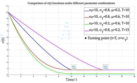
Figure 1.
Plots of the prescribed performance function under different parameter combinations.
To enforce the angular constraint condition, an unconstrained variable is constructed by combining the constrained state error with the prescribed performance function. A controller is then designed based on this variable to ensure that the system state error consistently satisfies the desired angular trajectory constraints during convergence. To establish time-varying upper and lower bound constraints for the state error, the relative error is defined as , given by
Correspondingly, the relative error has a boundary value expressed as
Next, the constrained relative error is transformed into an unconstrained variable for controller design. To address the inherent chattering issue in sliding mode control, an unconstrained mapping method incorporating an auxiliary function is proposed:
where is a switching term employed to maintain the continuity of the unconstrained mapping. For , ; for , . The parameter is introduced to increase the conservatism of the control method, thereby preventing the system from exceeding prescribed boundaries due to chattering. Through this mapping, the system’s relative error is transformed into an equivalent unconstrained variable . Furthermore, the relationship between the unconstrained variable and the system state error satisfies
where .
By employing prescribed performance functions and the unconstrained mapping method, this study effectively addresses system state constraints, thereby ensuring that angular constraints for all degrees of freedom in the 6-DOF underwater system are satisfied. Meanwhile, a fixed-time controller designed based on the unconstrained variable guarantees that the angular variation consistently follows the predefined tracking trajectory throughout the entire process.
3.2. Fixed-Time Terminal Sliding Mode Surface Design
Building upon the unconstrained variable designed in the previous section, a fixed-time terminal sliding mode surface with prescribed performance is constructed. Based on the BHP approach, this design ensures rapid fixed-time convergence and non-singularity during the sliding phase. Consequently, under the given constraints, the system states can achieve fixed-time stability on the sliding surface. The BHP-based fixed-time terminal sliding mode surface is expressed as follows:
where , , , , and satisfies
where parameters , , , and are used to ensure continuity during control law switching. By designing a piecewise function, the system singularity is effectively avoided. Their values are defined to achieve second-order continuous differentiability of the sliding mode surface, as specified below
Based on the above parameters, the sliding mode surface (46) satisfies the continuity condition:
According to Lemma 2, the unconstrained variable of the system can achieve fixed-time convergence. Under the action of the specified timing performance function and constraint conditions, the desired performance of the system on the sliding mode surface is guaranteed.
3.3. Input-Saturated Fixed-Time Sliding Mode Control with Prescribed Performance
In complex underwater environments, controllers may generate excessively large control signals to correct tracking errors, posing a risk that the output torque could exceed the saturation limits of the manipulator’s joint actuators. To address this practical engineering issue, this paper proposes an auxiliary system capable of compensating for input saturation within a fixed time. The control input that considers saturation effects can be represented by the following nonlinear function:
To meet the fixed-time tracking requirements, a fixed-time anti-windup auxiliary system is introduced:
where is the output of the auxiliary system; denotes the constructed sliding mode surface; and the parameters satisfy , , and .
The proposed control method consists of an equivalent control law and a reaching control law, which function during the sliding phase and the reaching phase of the sliding mode surface, respectively. The designed control law is expressed as
The equivalent control law is designed to ensure that the system exhibits the desired characteristics during the sliding phase of the sliding mode surface, expressed as follows:
Furthermore, Equation (53) ensures the fixed-time convergence of the unconstrained variable on the sliding mode surface. Meanwhile, the state error also converges within a fixed time according to the prescribed performance. The designed reaching control law enables the system to compensate for input saturation and reach the sliding mode surface within a fixed time, entering the sliding phase. It is formulated as follows:
Here, parameters and are used to ensure the fixed-time convergence characteristics of the system during the sliding mode reaching phase; regulates the convergence time of this phase, and represents the upper bound of the unknown disturbance , i.e., . The overall structure of the proposed control algorithm is shown in Figure 2.
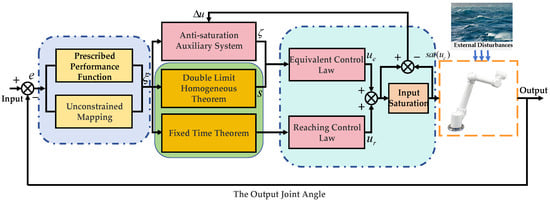
Figure 2.
Underwater manipulator schematic diagram.
3.4. Stability Analysis
Theorem 1.
Under the control law (50)–(54), the trajectory tracking system of the 6-DOF underwater manipulator achieves prescribed-performance fixed-time trajectory tracking in the presence of input saturation and external disturbances.
Proof of Theorem 1.
Based on the constraints given by Equations (41)–(43), the proof of the system’s fixed-time convergence can be structured in the following three steps:
- (1)
- Under input saturation, the system can reach the sliding surface within a fixed time and effectively reject external disturbances.
- (2)
- After the sliding surface is reached, the unconstrained variable converges in a fixed time during the sliding phase.
- (3)
- With the convergence of the unconstrained variable, the system’s tracking angular error also converges within a fixed time.
The first part is proven as follows. Consider the Lyapunov candidate function . Differentiating and substituting Equation (45) into yields
Substituting mapping models in (29), (44) and (49) into (55) yields
Based on the designed control method, Equation (56) can be further expanded as follows:
Simplifying the above Equation (57) further yields
By incorporating the constructed anti-windup auxiliary system, Equation (57) can be further transformed as
According to Yang’s inequality [25],
Substituting the above inequality into Equation (59) yields
Given that the inequality holds, Equation (61) can be reformulated as follows:
Since and , it follows that
From Lemma 3, the following inequality holds:
Equation (63) can then be rewritten as
According to Lemma 1, the system reaches the sliding mode surface and enters the sliding phase within a fixed time, satisfying
Next, the fixed-time convergence during the sliding phase needs to be proven. Based on the constructed sliding mode surface, the system exhibits distinct dynamics at different stages. Due to the piecewise characteristics of the sliding surface, the proof of fixed-time convergence in the sliding phase is divided into two parts. When the state variable satisfies , the sliding mode surface meets the following condition:
Define a Lyapunov function , whose time derivative is given by
According to Lemma 2, achieves fixed-time convergence, i.e.,
When the state variable satisfies , the following relation holds:
The derivative of can thus be reformulated as follows:
To further demonstrate the fixed-time convergence of the system, an auxiliary function is introduced:
From Equation (47), since , and , the above parameters satisfy
From the properties of Equation (72), and considering the monotonicity of the function, the following condition holds:
Then, Equation (71) can be further expressed as
Additionally, by defining and integrating both sides of Equation (76), we obtain
From Equations (41)–(44), the unconstrained variables and satisfy the following relation:
Therefore, the convergence rate of variable consistently dominates that of variable . According to Lemma 2, converges to within a fixed time, and the convergence time satisfies
Here, the neighborhood of the origin is defined as . The above analysis shows that the unconstrained variable achieves fixed-time convergence in both sub-sliding phases on the sliding mode surface, with the total convergence time satisfying
Finally, it remains to prove that the system state error can converge to the unconstrained variable within a fixed time. Based on the mapping relationship and variable definitions, the relationship between the unconstrained variable and the constrained state error satisfies
Equation (81) indicates that is the unique solution of . Therefore, the system error converges to the unconstrained variable within a fixed time, and the convergence time is given by
In summary, the fixed-time convergence of the 6-DOF underwater trajectory tracking system under the proposed control scheme has been proven. The proof of Theorem 1 is thus completed. □
4. Simulation
To systematically validate the comprehensive performance of the proposed control method, simulation experiments were conducted from the following two aspects: Firstly, a step signal was adopted as the system input to evaluate the performance of the proposed method in terms of dynamic response and steady-state accuracy by comparing it with recently advanced control algorithms. Secondly, the proposed algorithm was applied to the end-effector trajectory tracking control of a 6-DOF underwater manipulator, further verifying its engineering applicability and control effectiveness in complex working conditions. The controller parameters were set as follows: , , , , , , , , , . Parameters for the prescribed performance function were , , , . The DH parameters of the manipulator are shown in Table 1.

Table 1.
DH parameters of the underwater manipulator.
The proposed method was compared with the NFTSMC from reference [27] and the AFTSMC from reference [28], with key simulation results presented below. Figure 3 shows the step response of the six joint angles of the manipulator. It can be clearly observed that the proposed FT-PP-SMC-IS algorithm achieves faster response speed and smaller steady-state error compared to the other two methods. , where, , , , , , . , where , , , , , all are positive definite diagonal gain matrices. , , , , , , , , . The time-varying disturbance is .
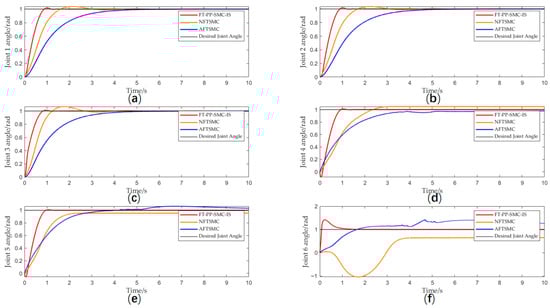
Figure 3.
(a) Joint 1 angle; (b) Joint 2 angle; (c) Joint 3 angle; (d) Joint 4 angle; (e) Joint 5 angle; (f) Joint 6 angle.
Figure 4 shows the angular velocity tracking performance for each joint of the manipulator. The proposed method maintains effective angular velocity tracking, whereas the AFTSMC approach in reference [28] exhibits severe chattering, which may lead to controller performance degradation and potential mechanical damage.
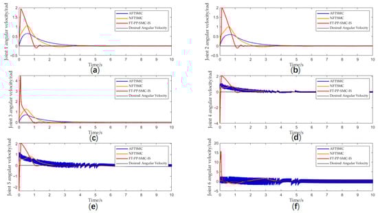
Figure 4.
(a) Joint 1 angular velocity; (b) Joint 2 angular velocity; (c) Joint 3 angular velocity; (d) Joint 4 angular velocity; (e) Joint 5 angular velocity; (f) Joint 6 angular velocity.
Compared with the benchmark algorithms, the proposed method effectively suppresses overshoot in joint angle tracking through prescribed performance boundaries, significantly mitigates response fluctuations caused by sliding mode chattering or external disturbances, and thereby ensures smoother motion of the manipulator. Meanwhile, by constraining the error range, the output torque of the actuator is indirectly limited, avoiding potential mechanical damage induced by severe chattering. Figure 5a–f present a comparison of the tracking errors of the three algorithms. Simulation results demonstrate that the proposed algorithm not only responds more rapidly and achieves the smallest steady-state error, but also strictly confines the tracking error within the bounds defined by the prescribed performance function throughout the entire control process. To quantitatively evaluate the control performance of the proposed algorithm, we conducted systematic comparative experiments with existing typical algorithms. Table 2 and Figure 6 present the tracking errors of the six joints of the underwater manipulator for each algorithm in numerical and visual forms, respectively. It can be clearly observed that, among all the compared algorithms, the proposed method achieves smaller tracking errors across all six joints, with a more concentrated and stable error distribution. This fully demonstrates that the proposed algorithm exhibits significant advantages in terms of overall tracking accuracy and stability, validating its effectiveness and superiority in complex underwater environments.
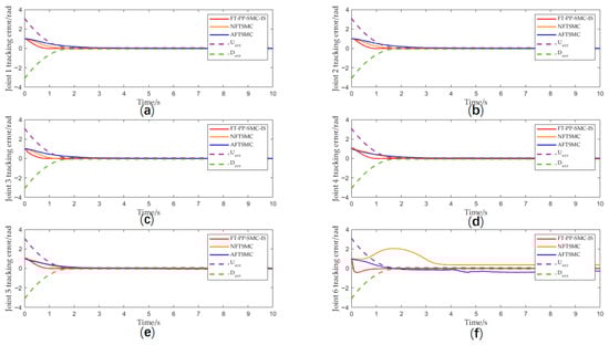
Figure 5.
(a) Joint 1 tracking error; (b) Joint 2 tracking error; (c) Joint 3 tracking error; (d) Joint 4 tracking error; (e) Joint 5 tracking error; (f) Joint 6 tracking error.
Table 2.
Joint tracking error comparison table for different algorithms.
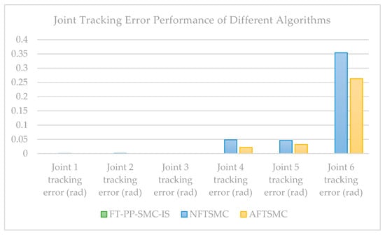
Figure 6.
Joint tracking error performance of different algorithms.
Balancing control accuracy with computational efficiency remains a key challenge in the application of underwater vehicle controllers. To evaluate this, simulation trials were conducted on a standard computing platform (Intel® Core™ i7-7700HQ CPU @ 2.80 GHz, 16.0 GB RAM, 64-bit OS). Over a 10-s simulation period (including graphical output operations), the total execution times for the three compared controllers were recorded: 74.923 s for NFTSMC, 71.4174 s for AFTSMC, and 76.5103 s for the proposed FT-PP-SMC-IS. These timings demonstrate that the computational cost of the proposed method is comparable to that of existing advanced schemes, incurring only a marginal increase in runtime.
Figure 7 presents a comparative analysis of the output torque generated by the three control methods under investigation. It can be observed that the NTSMC method without output limitation exhibits an excessively high peak torque, which may cause potential damage to the actuator. While the AFTSMC method demonstrates satisfactory steady-state performance in trajectory tracking, its output torque exhibits significant chattering that could also adversely affect the actuator. In contrast, the proposed FT-PP-SMC-IS method not only achieves effective trajectory tracking but also ensures smooth and saturation-free torque output, demonstrating well-balanced performance in both control accuracy and hardware protection.
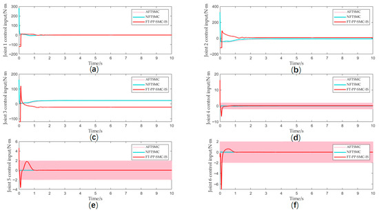
Figure 7.
(a) Joint 1 control input; (b) Joint 2 control input; (c) Joint 3 control input; (d) Joint 4 control input; (e) Joint 5 control input; (f) Joint 6 control input.
In practical engineering applications, underwater manipulators are often employed for various complex and precise operational tasks, where the tracking accuracy and stability of the end-effector directly determine the success of mission execution. Therefore, to comprehensively evaluate the overall performance of the proposed control algorithm, this study first validates its fundamental dynamic characteristics through step signal tests, and subsequently applies the method to the end-effector trajectory tracking control of a 6-DOF underwater manipulator. To comprehensively evaluate the algorithm’s control potential in practical engineering, this experiment simulated a realistic underwater environment to verify its adaptability and robustness under complex conditions such as model uncertainties, flow disturbances, and actuator saturation. The desired end-effector trajectory components of the manipulator are , , and . Figure 8 shows the 3D end-effector trajectory tracking results.
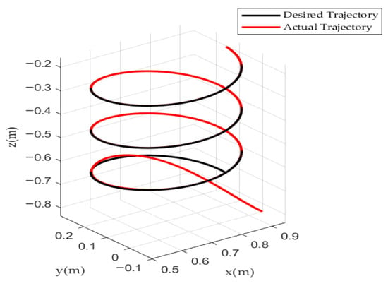
Figure 8.
The 3D end-effector trajectory tracking results.
Figure 9 demonstrates the tracking performance of each joint in 3D trajectory tracking, and Figure 10 shows that the tracking errors of all joints strictly satisfy the prescribed performance requirements. Distal joints exhibit greater sensitivity to disturbances due to stronger dynamic coupling and relatively lower inertia.
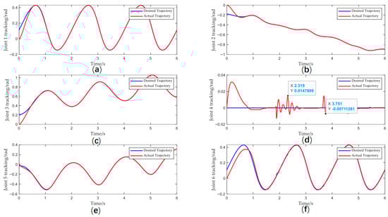
Figure 9.
(a) Joint 1 tracking; (b) Joint 2 tracking; (c) Joint 3 tracking; (d) Joint 4 tracking; (e) Joint 5 tracking; (f) Joint 6 tracking.
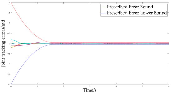
Figure 10.
Individual joint errors.
5. Conclusions
This paper proposes an FT-PP-SMC-IS method for underwater manipulators. The developed controller maintains excellent dynamic and steady-state performance under input saturation conditions. By incorporating a prescribed performance function to constrain tracking errors, it ensures fixed-time convergence in both the sliding mode reaching and sliding phases, ultimately achieving global fixed-time stability for the desired trajectory. Based on Lyapunov stability theory, the fixed-time stability of the closed-loop system is rigorously proven. Simulation and experimental results demonstrate the effectiveness of the proposed method, showing outstanding performance in both trajectory tracking accuracy and disturbance rejection capability. In future research, we will further investigate the influence mechanisms of time-varying hydrodynamic forces on the motion performance of underwater manipulators, aiming to develop a dynamic model that more accurately reflects real-world underwater conditions. Additionally, we will systematically explore controller parameter optimization by leveraging intelligent optimization algorithms and multi-objective trade-off strategies. This work seeks to enhance the system’s adaptability, robustness, and control precision across various operating conditions, thereby advancing underwater robotic manipulation technology toward higher efficiency and greater stability.
Author Contributions
Conceptualization, R.W. and W.H.; methodology, R.W., W.H. and H.W.; validation, R.W., W.H. and Z.L.; formal analysis, R.W. and W.H.; investigation, R.W., W.H. and H.W.; resources, R.W., H.W. and Y.S.; data curation, R.W., W.H. and Z.L.; writing—original draft preparation, R.W.; visualization, R.W.; supervision, H.W.; project administration, W.H. and R.W. All authors have read and agreed to the published version of the manuscript.
Funding
This research received no external funding.
Data Availability Statement
The original contributions presented in this study are included in the article. Further inquiries can be directed to the corresponding authors.
Conflicts of Interest
The authors declare no conflicts of interest.
References
- Pistone, A.; Ludovico, D.; Casareto, L.D.V.M.; Leggieri, S.; Canali, C.; Caldwell, D.G. Modelling and Control of Manipulators for Inspection and Maintenance in Challenging Environments: A Literature Review. Annu. Rev. Control 2024, 57, 100949. [Google Scholar] [CrossRef]
- Sivcev, S.; Coleman, J.; Omerdic, E.; Dooly, G.; Toal, D. Underwater Manipulators: A Review. Ocean Eng. 2018, 163, 431–450. [Google Scholar] [CrossRef]
- Li, J.; Zhou, B.; Huang, B.; Huang, W. Distributed Event-Driven Optimal Control for Networked Unmanned Surface Vehicles with Long Transmission Delays: A Memory-based Estimation and Communication Assignment Approach. IEEE Internet Things J. 2025, early access. [Google Scholar] [CrossRef]
- Wang, R.; Huang, W.Q.; Wu, J.Y.; Wang, H.; Li, J.X. Global Fast Terminal Sliding Mode Control of Underwater Manipulator Based on Finite-Time Extended State Observer. J. Mar. Sci. Eng. 2025, 13, 1038. [Google Scholar] [CrossRef]
- Moulay, E.; Lechappe, V.; Bernuau, E.; Plestan, F. Robust Fixed-Time Stability: Application to Sliding-Mode Control. IEEE Trans. Autom. Control 2022, 67, 1061–1066. [Google Scholar] [CrossRef]
- Moulay, E.; Léchappé, V.; Bernuau, E.; Defoort, M.; Plestan, F. Fixed-Time Sliding Mode Control with Mismatched Disturbances. Automatica 2022, 136, 110009. [Google Scholar] [CrossRef]
- Liu, Z.; Zhang, O.; Gao, Y.B.; Zhao, Y.; Sun, Y.Z.; Liu, J.X. Adaptive Neural Network-Based Fixed-Time Control for Trajectory Tracking of Robotic Systems. IEEE Trans. Circuits Syst. II 2023, 70, 241–245. [Google Scholar] [CrossRef]
- Xu, J.; Liu, W.; Li, L.; Yang, G.; Guo, L. Implicit Rigid Tube Model Predictive Control for Underwater Manipulators with Adaptive Sliding Mode Strategy. Ocean Eng. 2025, 324, 120682. [Google Scholar] [CrossRef]
- Zhang, M.; Song, G.; Mao, J.; Wang, F.; Zhou, J.; Song, A. Chattering Suppression and Hydrodynamic Disturbance Estimation of Underwater Manipulators Using Adaptive Fuzzy Sliding Mode Control. Trans. Inst. Meas. Control 2024, 46, 155–166. [Google Scholar] [CrossRef]
- Ge, D.; Wang, G.; Ge, J.; Xiang, B.; You, Y.; Feng, A. Trajectory Tracking Control of Two-Joint Underwater Manipulator in Ocean-Wave Environment. Ocean Eng. 2024, 292, 116329. [Google Scholar] [CrossRef]
- Zhong, Y.; Yang, F. Dynamic Modeling and Adaptive Fuzzy Sliding Mode Control for Multi-Link Underwater Manipulators. Ocean Eng. 2019, 187, 106202. [Google Scholar] [CrossRef]
- Liu, M.; Tang, Q.; Li, Y.; Liu, C.; Yu, M. A Chattering-Suppression Sliding Mode Controller for an Underwater Manipulator Using Time Delay Estimation. J. Mar. Sci. Eng. 2023, 11, 1742. [Google Scholar] [CrossRef]
- Zhao, P.; Gao, Z.; Chen, Y.; Chen, M.; Wang, J.; Zhang, J.; Yang, Y. Robust Control of Vibration-Based Manipulator with Variable Gain Integral Sliding Mode Strategy. J. Vib. Eng. Technol. 2025, 13, 320. [Google Scholar] [CrossRef]
- Liu, Z.; Zhao, Y.; Zhang, O.; Chen, W.; Wang, J.; Gao, Y.; Liu, J. A Novel Faster Fixed-Time Adaptive Control for Robotic Systems With Input Saturation. IEEE Trans. Ind. Electron. 2024, 71, 5215–5223. [Google Scholar] [CrossRef]
- Huang, H.; Tang, G.Y.; Chen, H.X.; Wang, J.J.; Han, L.J.; Xie, D. Adaptive non-singular fixed-time sliding mode control of moving-base underwater flexible manipulators. Nonlinear Dyn. 2024, 112, 4529–4550. [Google Scholar] [CrossRef]
- Zaare, S.; Soltanpour, M.R. Uncertainty and Velocity Observer-Based Predefined-Time Nonsingular Terminal Sliding Mode Control of the Underwater Robot Manipulators. Eur. J. Control 2024, 75, 100939. [Google Scholar] [CrossRef]
- Li, H.; Cai, Y. Fixed-Time Non-Singular Terminal Sliding Mode Control with Globally Fast Convergence. IET Control Theory Appl. 2022, 16, 1227–1241. [Google Scholar] [CrossRef]
- Gao, Z.; Zhang, Y.; Guo, G. Fixed-Time Prescribed Performance Adaptive Fixed-Time Sliding Mode Control for Vehicular Platoons With Actuator Saturation. IEEE Trans. Intell. Transp. Syst. 2022, 23, 24176–24189. [Google Scholar] [CrossRef]
- Lin, Z.; Wang, H.; Karkoub, M.; Shah, U.; Li, M. Prescribed Performance Based Sliding Mode Path-Following Control of UVMS with Flexible Joints Using Extended State Observer Based Sliding Mode Disturbance Observer. Ocean Eng. 2021, 240, 109915. [Google Scholar] [CrossRef]
- Heshmati-Alamdari, S.; Bechlioulis, C.P.; Karras, G.C.; Nikou, A.; Dimarogonas, D.V.; Kyriakopoulos, K.J. A Robust Interaction Control Approach for Underwater Vehicle Manipulator Systems. Annu. Rev. Control 2018, 46, 315–325. [Google Scholar] [CrossRef]
- Qin, H.; Yang, H.; Sun, Y.; Feng, L. Fixed-Time Stable Bilateral Teleoperation of Underwater Manipulator Using Prescribed Performance Terminal Sliding Surfaces. J. Frankl. Inst. 2023, 360, 3280–3306. [Google Scholar] [CrossRef]
- Cai, M.; Wang, Y.; Wang, S.; Wang, R.; Tan, M. Autonomous Manipulation of an Underwater Vehicle-Manipulator System by a Composite Control Scheme With Disturbance Estimation. IEEE Trans. Autom. Sci. Eng. 2024, 21, 1012–1022. [Google Scholar] [CrossRef]
- Moon, J.; Bae, S.-H.; Cashmore, M. Meta Reinforcement Learning Based Underwater Manipulator Control. In Proceedings of the 2021 21st International Conference on Control, Automation and Systems, Jeju, Republic of Korea, 12–15 October 2021. [Google Scholar]
- Sedghi, F.; Arefi, M.M.; Abooee, A.; Yin, S. Distributed Adaptive-Neural Finite-Time Consensus Control for Stochastic Nonlinear Multiagent Systems Subject to Saturated Inputs. IEEE Trans. Neural Netw. Learn. Syst. 2023, 34, 7704–7718. [Google Scholar] [CrossRef] [PubMed]
- Tian, Y.; Du, C.; Lu, P.; Jiang, Q.; Liu, H. Nonsingular fixed-time attitude coordinated tracking control for multiple rigid spacecraft. ISA Trans. 2022, 129, 243–256. [Google Scholar] [CrossRef]
- Song, J.; Tan, Y.C.; Zhang, L.Y.; Liu, S. An Optimal Energy-Saving Coordination Control System for Sail-Propeller of Wind-Assisted Ships. IET Intell. Transp. Syst. 2025, 19, e70090. [Google Scholar] [CrossRef]
- Sun, G.F.; Zhao, E.Q.; Zhang, G.J.; Huang, M.Y. Nonsingular fast terminal sliding mode control for robotic manipulators based on disturbance observer compensation. Control Theory Appl. 2022, 39, 1506–1515. [Google Scholar]
- Wang, J.; Shen, Y.X. Adaptive fixed-time sliding mode control for robotic manipulators. Control Decis. 2024, 39, 1918–1926. [Google Scholar]


Disclaimer/Publisher’s Note: The statements, opinions and data contained in all publications are solely those of the individual author(s) and contributor(s) and not of MDPI and/or the editor(s). MDPI and/or the editor(s) disclaim responsibility for any injury to people or property resulting from any ideas, methods, instructions or products referred to in the content. |
© 2025 by the authors. Licensee MDPI, Basel, Switzerland. This article is an open access article distributed under the terms and conditions of the Creative Commons Attribution (CC BY) license.