Abstract
The strengthening performance of carbon-fiber-reinforced polymer (CFRP) in concrete structures primarily depends on the CFRP–concrete interfacial bond behavior. For CFRP-strengthened circular reinforced concrete (RC) pipe piles in marine environments, the interfacial bond behavior is susceptible to hygrothermal conditions. In this study, cylindrical concrete specimens were designed and subjected to pull-off tests to evaluate the CFRP–concrete interfacial performance under simulated marine environmental attacks (3 days in a 50 °C salt spray followed by 4 days of seawater immersion). The deterioration mechanism and failure modes of the CFRP–concrete bond behavior in such environments were analyzed, and relationship equations describing the interfacial bond degradation were proposed and validated. Test results indicated that the CFRP–concrete bond strength at circular interfaces is approximately 21% lower than that at planar interfaces. Under hygrothermal marine conditions, the average CFRP–concrete bond strength remained relatively stable in the early stages due to the competing effects of epoxy plasticization and post-curing, while variability increased significantly in later stages. For test specimens in Group A without concrete surface grinding before CFRP wrapping, an initial bond strength of 1.5 MPa was exhibited, while, for test specimens in Group B, with surface grinding, the initial bond strength started at 2.0 MPa. Both groups experienced a significant CFRP–concrete bond strength reduction of 0.4 MPa after the first wet–dry cycle, with the subsequent average strength stabilizing near initial values. Notably, Group B achieved a peak strength of 3.88 MPa at 84 days, attributed to surface grinding, which enhanced bond strength by 33% and delayed bond failure. The overall stable average strength resulted from averaging high-strength and degraded points. A bond degradation model based on averaged strength reduction was proposed: demonstrating a strength loss of 27%–36% after 98 days of accelerated marine environmental exposure. The proposed equations describing the interfacial bond degradation on a circular concrete surface predict well the flexural capacity of CFRP-wrapped RC beams under similar environmental conditions, where the calculated flexural capacity is 0.8 times the experimental value, confirming the model’s conservative and safe design applicability.
1. Introduction
In recent years, fiber-reinforced polymer (FRP) sheets have been widely used in concrete strengthening due to their high strength, light weight, and ease of construction [1,2,3]. When the concrete structure is damaged [4], the traditional repair methods are rather complicated. The use of FRP materials for reinforcement has been widely accepted, and their applications continue to expand [5,6]. However, in practical engineering applications, although FRP materials possess high tensile strength, failure modes are generally not caused by direct rupture of the FRP but by debonding due to insufficient interfacial strength between the FRP and concrete [7]. Environmental moisture can lead to degradation of the bond between FRP and concrete through plasticization, swelling, cracking, and hydrolysis [8,9]. The expansion of epoxy resin due to moisture absorption generates internal stresses, which affect the interfacial bond, leading to cracking and debonding. In turn, the weakening of the fiber–resin interfacial bond promotes further water diffusion [10]. Exposure of epoxy resins to temperatures near or above the glass transition temperature (Tg) can also lead to premature debonding failure in FRP-strengthened members [11,12]. However, exposure to relatively high temperatures below the Tg may induce post-curing effects that improve the mechanical properties of the resin [13], resulting in an increase in bond strength. ACI 440.2R-08 recommends a maximum service temperature of 15 °C below the glass transition temperature (Tg) and specifies an aging exposure duration of 1000 h [14]. Blackburn et al. recommended an accelerated hygrothermal test with a minimum aging period of 8 weeks (i.e., 1344 h) to balance the competing effects of post-curing and plasticization [15].
Numerous studies have investigated the long-term performance of FRP materials in chloride environments [16,17,18,19,20,21,22,23,24,25,26,27,28,29,30,31,32], with chloride solution concentration and exposure time being the primary variables [20,22]. Gholami et al. found that the reduction in tensile strength of CFRP was negligible after 8 months of immersion in a 5% salt solution but became significant after only 150 h in a 10% salt solution at the same immersion temperature [20]. In addition, for FRP-repaired RC elements, the low-viscosity epoxy resin can penetrate the microcracks and pore network of concrete via capillary action during construction. This penetration behavior forms a unique mechanical anchoring effect after the resin cures [23]. When the interface is subjected to debonding stress, the geometrically interlocked structure between the cured resin and the concrete substrate generates significant mechanical resistance.
The hygrothermal environment can also induce a post-curing effect in the epoxy resin. Here, “post-curing” refers to a secondary consolidation process involving increased cross-linking between polymer (epoxy) chains, which reduces internal stress [24]. Al-Lami et al. investigated the performance of epoxy resin exposed to warm water (40 °C) for up to 1500 h. The tensile strength and ultimate strain of the epoxy resin initially increased and then decreased during this exposure [25]. This initial increase can be attributed to the beneficial effects of the post-curing process, while the subsequent decrease is due to the negative impacts of the hygrothermal exposure, which ultimately outweigh the positive contributions of post-curing. The relatively minor change in the bond strength of the CFRP–concrete interface after cyclic exposure is because the tensile strength of the epoxy resin remains greater than that of the concrete, even after hygrothermal conditioning, allowing the epoxy to continue providing adequate strength [24]. The hygrothermal conditions promote secondary cross-linking between the epoxy resin and the concrete, reducing internal stress and increasing bond strength [24]. Additionally, several other adhesion mechanisms exist among them, including adsorption, mechanical interlocking, diffusion, and electrostatic mechanisms [26].
The direct pull-off test has gained widespread popularity due to its low cost, small specimen size, and operational convenience. Current research primarily focuses on the bond behavior of CFRP–flat concrete interfaces under various environmental conditions, such as hygrothermal exposure [27], wet–dry cycles [28], simulated marine environments [29], and real marine exposure [30]. In contrast, studies on the pull-off behavior of curved interfaces remain relatively scarce. This study conducts comparative pull-off tests on both curved and flat specimens, with a specific focus on investigating the mechanical performance of CFRP–curved concrete interfaces under high-temperature and high-humidity environmental conditions.
In the present paper, bond performance between CFRP and concrete in a marine environment was studied through pull-off tests. The degradation mechanism and failure modes of the of the CFRP–concrete bond behavior of the cylindrical concrete specimens subjected to simulated marine environmental attacks (3 days in a 50 °C salt spray environment followed by 4 days of seawater immersion) were investigated. Based on the fitting of the experimental results, degradation equations to describe the CFRP–concrete bond strength under marine exposure were obtained and validated.
As pointed out by Mata et al. [31], the pull-off test method has certain limitations, such as significant variability in results within a test series and the influence of the concrete substrate strength on the measured bond strength. Consequently, it is recommended to increase the number of specimens and utilize higher-strength concrete grades in laboratory investigations to help identify outliers and ensure test quality. In the present test study, these recommendations were considered in the experimental design.
2. Experimental Program
2.1. Materials
All concrete specimens were prepared with the identical mix proportion, as detailed in Table 1. The material properties of the CFRP and epoxy resin used in the test study are provided in Table 2 and Table 3, respectively.

Table 1.
Concrete mix proportion.
Table 2.
Characteristics of CFRP.
Table 3.
Epoxy properties.
2.2. Test Specimens
The experimental design involved the preparation of two groups totaling 15 cylindrical specimens and 48 concrete cube blocks, divided into Group A and Group B. Each group consisted of 8 cylindrical specimens and 24 cube blocks. The cylindrical specimens, with a diameter of 150 mm and a height of 300 mm, were used to test the tensile bond strength of CFRP. The cube blocks, measuring 100 × 100 × 100 mm, were used to determine the compressive strength of the concrete.
Two 300 × 150 × 150 mm rectangular specimens and two cylindrical specimens were also prepared to evaluate the difference in bonding performance between flat and circular surfaces.
2.3. Concrete Surface Treatment and CFRP Wrapping
Before CFRP wrapping, the surfaces of all cylindrical specimens were thoroughly cleaned. The concrete surfaces of the specimens in Group B were ground to achieve a specific texture for comparative purposes. Epoxy resin adhesive was evenly applied to the surface of the specimens, after which pre-cut CFRP sheets were smoothly wrapped around them to eliminate air bubbles and ensure compactness. A second layer of adhesive was applied onto the CFRP surface to guarantee complete fiber saturation and uniform coating. The resin matrix, being a nonpolar material, contains hydrophilic groups (e.g., hydroxyl, carboxyl) on its main or side chains. These groups can physically adsorb water molecules through secondary valence bonds, forming a layer of bound water. This bound water is relatively stable, with strong adsorption, and it contributes to the formation of the strengthening system by interacting with both the concrete and FRP materials, facilitating a stable complexation mechanism at the interface.
The interface was inspected to ensure the absence of voids or delamination defects and then the specimens were subjected to indoor curing for 7 days followed by environmental corrosion. The fabrication process and the final specimen are shown in Figure 1.
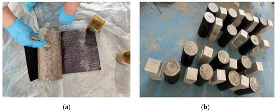
Figure 1.
During (a)/after (b) CFRP wrapping of curved specimens.
Two 300 × 150 × 150 mm rectangular specimens and two cylindrical specimens were also prepared to evaluate the difference in bonding performance between flat and curved surfaces. One rectangular specimen and one cylindrical specimen were polished to compare the effect of surface treatment on the bonding performance of flat and curved surfaces.
2.4. Accelerated Hygrothermal Marine Environmental Attack Test
To reproduce the degradation experienced by CFRP-repaired RC pipe piles in the marine splash zone, where hot and humid conditions often prevail, a salt spray chamber was employed in the laboratory to provide a high-temperature and humid atmosphere.
A relatively high temperature was selected to accelerate salt spray and thermal effects. The temperature of 50 °C was chosen to represent the upper range of surface temperatures that concrete structures can reach under direct solar radiation in hot marine climates. The 3.5% NaCl concentration corresponds to the average salinity of the seawater. The cured CFRP–curved specimens were placed in the salt spray chamber at 50 °C to simulate the high-temperature and high-humidity marine environment. The salt spray chamber is shown in Figure 2a. After three days of salt spray exposure in the chamber (see Figure 2b), the specimens were removed and immersed in simulated seawater with a 3.5% NaCl concentration for four days to replicate the seawater conditions in the splash zone (see Figure 2c). Thus, one full cycle consisted of seven days (three days of salt spray followed by four days of immersion), accounting for the alternating wet–dry cycles, the deposition of salt spray, and the immersion in seawater. The specimens were then returned to the salt spray chamber for the next high-temperature salt spray cycle. A total of 14 cylindrical specimens and 42 concrete cubes were subjected to this simulated marine environmental exposure, while the left 2 cylinders and 6 concrete cubes were placed in the laboratory as referenced test specimens. The mix proportion for the simulated seawater was as follows: the amounts of NaC1, MgSO4, and MgC12 per liter were 26.518 g, 3.305 g, and 2.447 g, respectively.
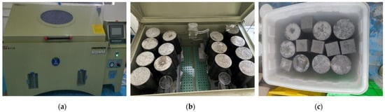
Figure 2.
Salt spray chamber and accelerated marine environmental attack ((a) salt spray chamber; (b) salt spray in the chamber; (c) immersed in simulated seawater).
2.5. Pull-Off Test
After the accelerated marine environmental attack test, pull-off tests were carried out on the CFRP-wrapped test specimens. Prior to testing the CFRP–concrete interface strength, the surface of the CFRP-wrapped test specimens was thoroughly cleaned. For CFRP-wrapped cylindrical test specimens, multiple measurement points were randomly selected around the circumferential surface of the specimens. A hand-held drilling machine equipped with a 40 mm diameter circular bit—matching the size of the steel block used for adhesion testing—was employed to pre-cut circular notch grooves. These grooves, with a depth of 2–3 mm, were designed to isolate the test area from the surrounding CFRP. After cutting, any concrete dust in the test area was removed to ensure a clean surface free of contaminants. Multiple points were notched in this manner. The drilling setup and a specimen after notching are shown in Figure 3.
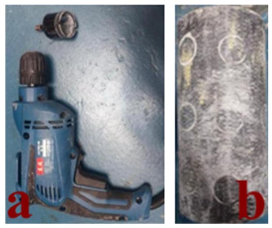
Figure 3.
(a) Drilling machine and (b) cylindrical specimen after notching.
A pull-off adhesion tester (see Figure 4) was used to perform the bond strength tests on both curved and flat surfaces. The pull-off testing process for the curved specimen is shown in Figure 5b. For comparison with flat specimens, the same pull-off protocol was also tested on the surfaces of the CFRP-strengthened flat test specimens, and the testing process is shown in Figure 5a. After completing the pull-off test, the CFRP in the tested area was detached, exposing the underlying concrete surface, as shown in Figure 6a,b.
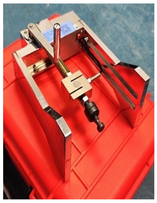
Figure 4.
Pull-off testing equipment.
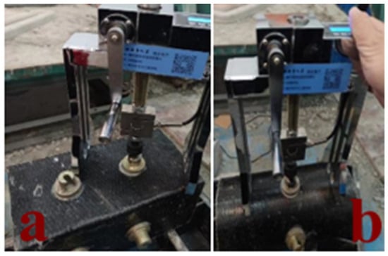
Figure 5.
Pull-off test on test specimens: (a) flat surface; (b) circular surface.
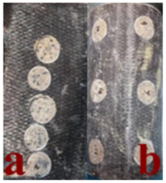
Figure 6.
Flat and circular specimens after test: (a) on flat surface; (b) on circular surface.
3. Test Results and Analysis
3.1. Analysis of Pull-Off Test Results on Circular and Planar Surfaces
The pull-off strength is calculated as follows:
where is the bond strength (MPa); is the failure load (kN); and is the bonded area of the steel block (40 mm diameter) in Figure 5 (mm2).
Since the same cutting drill bit (with a diameter of 40 mm) was used for both flat and curved surfaces, their projected areas on the flat plane are identical. The bond strength calculated using the projected area differs by only 1% from that obtained with the actual curved surface area. Therefore, when determining the area S for pull-off strength calculation, modeling software was used to measure the actual bonded area between the cut curved surface and the steel block. The test area for the planar rectangular specimen was Sflat = 1256.637 mm2, while that for the cylindrical specimen was Scurved = 1268.1266 mm2. The difference in area between the two is negligible. Based on the test results, the pull-off strength of the curved specimens was approximately 21% lower than that of the flat specimens, as shown in Figure 7. Similar findings were reported in Ref. [32], where CFRP was used to strengthen piers and bridge beams. Field pull-off tests indicated that the bond strength on cylindrical piers was about 20% lower than the average bond strength measured on bridge beams. The results of this experiment are consistent with those field observations.
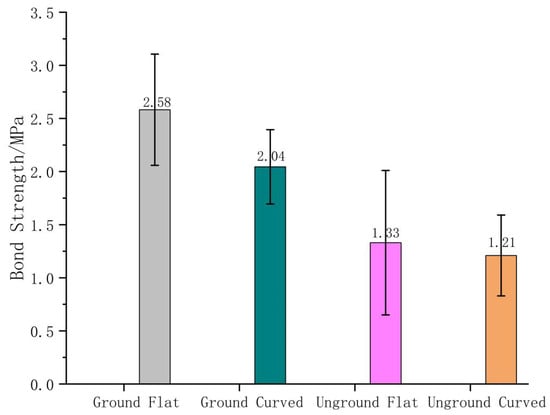
Figure 7.
Bond strength on curved vs. flat surfaces of the test specimens.
Surface grinding treatment of the concrete before CFRP wrapping significantly enhanced the bond strength. The increased surface roughness resulting from grinding improved the initial average bond strength to 2 MPa (see Figure 7). The epoxy resin, upon curing, provides mechanical bonding through interlocking and frictional forces. These mechanisms, combined with the chemical adhesion between epoxy and concrete, form a composite bonding interface [33]. Consequently, the average bond strength increases while the experimental scatter decreases, indicating that surface treatment effectively improves bond performance and reduces variability caused by concrete heterogeneity.
The discrepancy in bond strength between flat and curved CFRP-wrapped test specimens is attributed to differences in load transfer efficiency. While flat specimens exhibit uniform stress distribution (see Figure 8a), curved surfaces experience load transfer losses due to their geometrical characteristics (see Figure 8b). The observed 21% reduction in bond strength for curved specimens suggests that approximately 21% of the bonded area near the edges of the steel block may not contribute effectively to load transfer. As shown in Figure 8c, assuming a bond layer thickness of 0.2 mm between the steel block and the CFRP, a peripheral region exceeding 1.93 mm in width may be considered ineffective in transmitting bond stresses (Figure 8d).
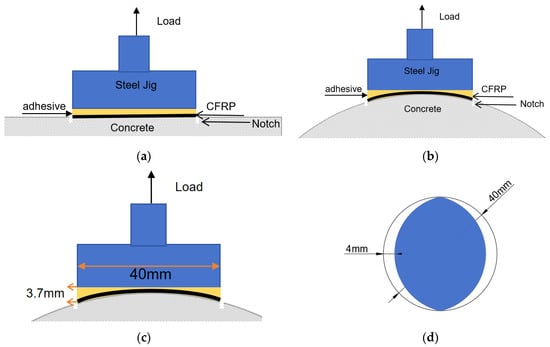
Figure 8.
Schematic diagram of the CFRP–concrete interfacial zones under pull-off load ((a) schematic diagram on flat surface; (b) schematic diagram on curved surface; (c) assumed effective bond area; (d) edge distance on curved surfaces).
3.2. Bond Strength of the CFRP-Wrapped Cylindrical Specimens Subjected to Different Durations of Accelerated Hygrothermal Marine Environmental Attacks
For CFRP-wrapped cylindrical specimens, test points were uniformly distributed along the circumference of each cylinder, with 15 points tested in each test specimen. The recorded data were used to calculate the interfacial bond strength according to Equation (1). The results are summarized in Figure 9, where the CFRP–concrete bond values are the average strength of the 15 tested points of each cylindrical specimen.
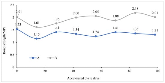
Figure 9.
CFRP–concrete bond strength in cylindrical specimens of Group A and Group B.
In Group A, the occurrence of high-strength points in the later stage, with individual bond strength reaching maximum values, can be attributed to the post-curing of the epoxy resin and its deeper penetration into the microcracks of the concrete in the hot and humid environment, resulting in enhanced mechanical interlocking. However, the overall average bond strength remained relatively low. When converted to equivalent flat surface strength, some measurement points exhibited strengths below 2.5 MPa, indicating non-compliant performance. This is primarily due to the smooth concrete surface, which was primarily composed of a mortar layer lacking roughness. Without a textured interface, the epoxy resin could not form a sawtooth-like bonding interface or generate mechanical friction, leading to an initial average bond strength of only 1.53 MPa. After degradation in the high-temperature and high-humidity marine environment, the surface deteriorated further, resulting in less concrete being attached to the CFRP during pull-off tests. This increased the variability of the test results and caused bond failures at individual points, manifested by the absence of concrete residue on the CFRP surface after testing.
In Group B, the highest bond strength appeared in the later stage, reaching a maximum stress of 3.88 MPa—the highest value observed in all curved-surface pull-off tests. However, bond failure points also occurred simultaneously. The average bond strength at this stage was 2.18 MPa, the highest recorded for this group, indicating a bimodal distribution of bond strength with both enhanced and degraded interfacial performance. The specimens in Group B were treated with an angle grinder to increase surface roughness, which improved the initial average bond strength to 2 MPa. In CFRP-wrapped cylindrical concrete specimens, surface grinding before CFRP application increased the CFRP-concrete bond strength by 33% and delayed the occurrence of bond failure after 84 days. After curing, the epoxy resin provided mechanical interlocking resistance composed of contact and friction forces, contributing to a composite bonding interface between the epoxy and concrete, indicating that the mechanical interlocking is one of the primary mechanisms governing the bond between FRP and concrete [33].
It can be concluded that surface roughness is one of the key mechanisms for enhancing bond strength. Similar techniques include the groove bonding method, U-wrapping anchorage, near-surface mounted reinforcement, and hybrid FRP bonding [34]. In engineering practice, surface sand-blasting is also widely used to increase roughness and improve interfacial bond strength. Nevertheless, with prolonged exposure to aggressive environments, surface concrete inevitably undergoes degradation, which weakens the interfacial bond strength. The uncertainty in the pull-off test results primarily stems from the heterogeneity of concrete aggregates and voids, while the hot and humid conditions exacerbated interfacial degradation, leading to increased data scatter.
The initial increase in CFRP–concrete pull-off can be attributed to the beneficial effects of epoxy post-curing, while the subsequent decrease is due to the negative impact of hygrothermal exposure, which eventually outweighs the positive contributions of post-curing. Thus, a decline in bond strength was observed in later stages. However, the average bond strength after 70 days did not decrease significantly because the pull-off tests captured higher bond strength values that offset the average strength reduction caused by degradation. Al-Lami et al. [25] investigated the behavior of epoxy resin exposed to warm water (40 °C) for up to 1500 h. They reported an initial increase followed by a decrease in tensile strength and ultimate strain of the epoxy resin, which is consistent with the bond strength trends observed in this experiment.
3.3. Bond Failure Modes of the CFRP-Wrapped Cylindrical Specimens Subjected to Different Durations of Accelerated Hygrothermal Marine Environmental Attacks
Pull-off test results were classified based on failure modes. The desirable failure mode is proper adhesion of FRP to concrete, where the FRP material remains tightly bonded to the concrete surface and the pull-off strength exceeds the shear strength of the concrete. This is considered the desirable failure mechanism.
According to the ASTM D7522/D7522M standard [35], in the pull-off test, failure modes of CFRP–concrete interfaces are categorized as follows: (1) invalid measurements due to the debonding between the steel block and CFRP; (2) adhesive failure due to the failure of the epoxy resin adhesive; (3) mixed failure due to the failure of the epoxy resin adhesive and concrete; (4) cohesive failure in the concrete substrate.
For FRP-wrapped rectangular concrete test specimens, after immersion in 60 °C seawater for 4 days followed by 3 days of laboratory drying, the failure modes of the FRP–concrete interfaces changed with the wetting–drying cycling [36]. For the CFRP-wrapped cylindrical concrete specimens in the present test, the change of the failure modes of the CFRP–concrete interface after different durations of accelerated marine environmental attacks (3-day 50 °C salt spray and 4-day seawater immersion cycling) is shown in Figure 10.
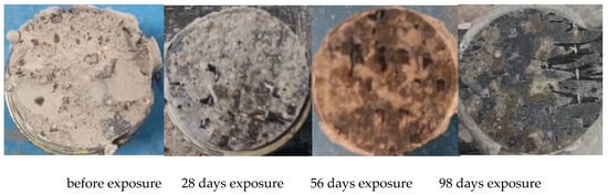
Figure 10.
Failure modes of CFRP–concrete interface in the cylindrical specimens after 3-day 50 °C salt spray and 4-day seawater immersion cycling.
By comparing the results of Ref. [36] and the present test, it can be concluded that exposure to salt spray and seawater cycling led to failure primarily within the concrete layer adjacent to the CFRP. Before exposure, the pulled-off CFRP surfaces were largely covered with concrete, indicating cohesive failure. After three months of hygrothermal cycling, failure occurred at the interface between the epoxy resin and the concrete, or within the resin layer itself. After multiple cycles of environmental degradation, mixed failure became the dominant failure mode in all specimens. In the experimental study by Dil et al. [36], test results demonstrated a gradual reduction in concrete attached to the CFRP after pull-off testing, with a transition from cohesive to mixed failure. Despite this, the pull-off strength remained around 2 MPa throughout the two-year period. A comparison with the present experiment reveals a consistent transition to mixed failure after environmental exposure. In both cases, less concrete adhered to the FRP surface following pull-off testing, indicating similar failure mechanisms under comparable corrosive conditions.
From Table 4 and Table 5, it can be seen that, due to the grinding process on the concrete surface before CFRP wrapping, the bond failure in Group B occurred less frequently, and the internal cohesion failure time was prolonged. However, for both groups of CFRP-wrapped cylindrical specimens, the failure mode of the pulled-off CFRP surfaces completely transformed into mixed failure after a 56-day accelerated marine environmental attack.
Table 4.
Percentage of destruction patterns in Group A.
Table 5.
Percentage of destruction patterns in Group B.
Thus, for the CFRP-wrapped cylindrical concrete specimens subjected to different durations of accelerated marine environmental attacks (3-day 50 °C salt spray and 4-day seawater immersion cycling), several typical failure modes were observed:
- Adhesive failure: This failure mode resulted from experimental inaccuracies. Compared to other measurement points on the same specimen, no concrete adhesion was observed on the CFRP surface after pull-off testing. This phenomenon was observed across various time periods in Group A. Due to its weaker initial bond strength, Group A was more susceptible to bond failure. In contrast, bond failure occurred in Group B only on the 86th day, indicating that the surface treatment measures effectively delayed the onset of such failure. The adhesive failure in the CFRP–concrete interface is shown in Figure 11.
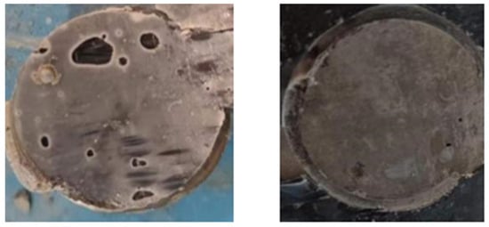 Figure 11. Adhesive failure in the CFRP–concrete interface of the cylindrical concrete test specimens.
 - Concrete failure: This failure mode occurred simultaneously with adhesive failure and was a sufficient condition for adhesive failure, though adhesive failure did not necessarily imply concrete failure. During testing, the concrete surface in the test area remained undamaged by the pull-off test but exhibited lower strength compared to other regions. This was confirmed using a rebound hammer, which caused failure in the weakened concrete area upon testing. Concrete failure in the CFRP–concrete before and after rebound tester testing is shown in Figure 12.
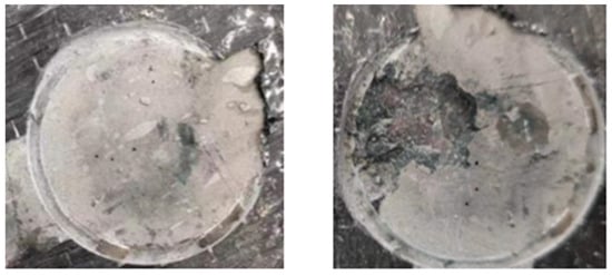 Figure 12. Concrete failure in the CFRP–concrete interface of the cylindrical concrete specimens before and after rebound hammer testing.
 - Mixed failure: This mode involved a combination of cohesive failure within the concrete and adhesive failure at the epoxy–concrete interface. Rebound hammer tests revealed lower strength values in areas of cohesive concrete failure and higher strength values in areas of interfacial failure. This discrepancy arose because cohesive failure occurred in weaker concrete zones, whereas interfacial failure exposed stronger concrete regions. The mixed failure in the CFRP–concrete interface is shown in Figure 13.
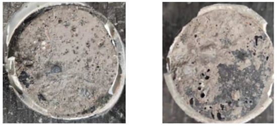 Figure 13. Mixed failure in the CFRP–concrete interface of the cylindrical concrete specimens.
Based on the experimental results, the failure modes observed in curved cylindrical concrete specimens after pull-off testing under hygrothermal marine conditions were classified into three types, as summarized in Table 6.
Table 6.
Summary of the failure modes of the CFRP–concrete interface in the cylindrical specimens subjected to different durations of accelerated hygrothermal marine environmental attacks.
4. Degradation Equation of CFRP–Concrete Interfacial Bond Strength Under Hygrothermal Marine Environmental Attacks
Over the 98-day experimental period, although the average CFRP–concrete interfacial bond strength in cylindrical specimens showed little overall change, the variability of the measurements increased significantly. In the later stages, some measured points exhibited higher bond strengths. This phenomenon can be attributed to the post-curing effect of the epoxy resin and its deeper penetration into the surface pores of the concrete under hot and humid environmental conditions, which enhanced mechanical interlocking and frictional resistance. The combined contribution of these mechanisms ultimately outweighed the plasticization effect of the hygrothermal environment on the epoxy resin.
In Group B, after hygrothermal marine environmental cycling, pull-off tests revealed both high-strength points and failure points. The data from this group demonstrate a more pronounced divergence in bond strength during the later stages of the experiment. Therefore, data from Group B were selected to generate frequency distribution diagrams, as they more clearly reflect the influence of the high-temperature and high-humidity marine environment on CFRP–concrete bond strength (see Figure 14). As can be seen from Figure 14a, after Day 0~Day 14 of the accelerated marine environmental attack, the measured bond strengths were relatively concentrated between 1.5 MPa and 2.0 MPa. In contrast, Figure 14b shows that, between Day 84 and Day 98, the bond strengths exhibited a more uniform distribution trend. This indicates that the CFRP–concrete interfacial bond in the curved concrete specimens was degraded by the high-temperature, high-humidity marine environment, resulting in a divergence of bond strength values rather than a concentrated distribution. In all accelerated marine environmental attacks, the average bond strength changed little, although a flattened distribution with the emergence of both higher and lower strength points is shown in Figure 14b. Therefore, it is suggested that, in the evaluation of the pull-off test results, both the average CFRP–concrete interfacial bond strength and the distribution characteristics and variability of the data must be considered.
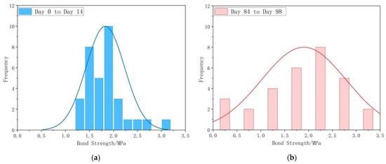
Figure 14.
Histograms of the CFRP–concrete bond strength distribution in test specimens of Group B at different marine environmental attack stages ((a) Day 0 to Day 14; (b) Day 84 to Day 98).
4.1. CFRP–Concrete Interfacial Bond Strength Degradation Equation of Group A
Since the pull-off test is a partial measurement of the CFRP–concrete bond strength, a single data point cannot represent the overall bond strength. Therefore, we conducted 15 pull-off tests on each specimen—a key difference from conventional testing methods. More measurement points provide a more comprehensive reflection of the bond strength distribution. For Group A, the average bond strength remained constant in the later stage of the tests, which was deemed unreasonable. To address this, we processed the test data to derive a “degradation-average curve”. This curve is not a constitutive stress–strain model but specifically describes the bond strength deterioration on curved surfaces. It serves as a practical tool for engineers to evaluate the degradation of CFRP-strengthened members in actual engineering projects, based on the CFRP–concrete bond strength obtained from pull-off tests.
To determine whether the bond performance of the CFRP–concrete curved interface in the test area was degraded by environmental exposure, the measured data were categorized based on the initial average pull-off strength. Values below the initial average bond strength were considered indicative of an accelerated marine environmental attack, while data exceeding this value were excluded. The initial average bond strength for Group A was 1.53 MPa. After filtering out values above this threshold, the remaining bond strength points (below 1.53 MPa) were averaged to quantify the extent of degradation.
The degraded bond strength data of Group A were fitted to obtain the CFRP–concrete interfacial bond strength degradation equation of the curved CFRP-wrapped concrete specimens subjected to hygrothermal marine environmental attacks, as expressed by Figure 15 and Equation (2):
where is the CFRP–concrete interfacial bond strength (MPa) and is the durations of the accelerated hygrothermal marine environmental attacks (day).
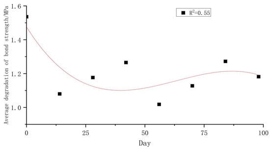
Figure 15.
Fitted equation of degraded average bond strength for Group A.
4.2. CFRP-Concrete Interfacial Bond Strength Degradation Equation of Group B
Following the same data processing method as for Group A, the bond strength data of Group B were filtered and averaged to obtain the degraded average bond strength values. An exponential function was selected to fit the degraded bond strength data of Group B, as it provided a better fit and was more consistent with the theoretical model. The fitted equation is shown in Figure 16.
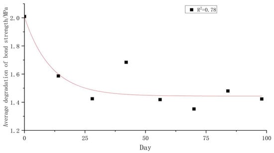
Figure 16.
Fitted equation of degraded average bond strength for Group B.
The resulting degradation equation for the curved interface bond strength of Group B under hygrothermal marine environment is given by Figure 16 and Equation (3):
where is the CFRP–concrete interfacial bond strength (MPa) and is the durations of the accelerated hygrothermal marine environmental attacks (day).
The fitting curve in this study is primarily intended to intuitively characterize the temporal degradation behavior of bond strength while providing a comparatively concise prediction reference for engineering practice. Distinct from the stress–strain constitutive model developed via shear tests, this curve focuses on trend characterization rather than describing fundamental physical mechanisms. Fitting curves are rarely employed in most pull-off test studies, largely due to two constraints: first, the inherent high dispersion of pull-off test data coupled with the limited number of measurement points in conventional tests fails to meet the requirements for reliable fitting; second, no unified standard exists for dedicated fitting models targeting bond strength degradation under marine environmental exposure. To address these limitations, this study enhanced data reliability by increasing the measurement density to 15 pull-off tests per specimen, effectively reducing data dispersion. Its parameters primarily reflect the degradation trend of bond strength under marine environmental actions, offering a quantitative basis for assessing the long-term performance of CFRP–concrete interfaces.
A simple average of all raw data misleadingly suggested stable bond strength, which conflicted with the observed flexural capacity degradation of CFRP-strengthened beams in similar marine environments. To resolve this discrepancy, the data were processed to isolate the “degrading-average” trend, which directly informed the development of Equations (2) and (3). Practically interpretable as environmental reduction factors for bond strength, these equations align conceptually with the reduction factors specified in design guidelines such as the guidance in Ref. [37] and the Chinese code GB50608-2020 [38] for marine applications.
5. Validation of the Fitted Degradation Equation for Bond Strength of Circular Interfaces in a Hygrothermal Marine Environment
The use of CFRP for strengthening RC elements significantly enhances their flexural capacities. However, in hygrothermal marine environments, the degradation of interfacial bond performance cannot be ignored, as it considerably affects the flexural behavior of strengthened RC elements. To validate the interfacial bond strength degradation equations derived from pull-off tests on circular RC elements in this study, the equation was applied to evaluate the flexural capacity of CFRP-strengthened RC beams under similar environmental conditions due to the few tests on the flexural capacity of CFRP-strengthened circular RC elements. The Chinese standard “GB 50608-2020 Technical standard for fiber reinforced polymer (FRP) in construction” [37] was followed to analyze the trend of flexural capacity degradation in hygrothermal environments and verify the proposed degradation equation formula.
5.1. Basic Information of the Tested RC Beams
The parameters of a tested RC beam [38] were as follows: The cross-section of the beam was 200 mm × 100 mm and the calculated span was 1600 mm (see Figure 17). The design concrete strength was C30 and the actual concrete cube compressive strength was 42.5 MPa. A 2Φ10 rebar with a yield strength of 333.3 MPa was used as tensile reinforcement. The thickness, tensile strength, and elastic modulus of the CFRP sheet were 0.167 mm, 3609 MPa, and 243 GPa, respectively.
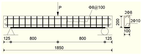
Figure 17.
Dimension and reinforcement of concrete beam.
Six CFRP-strengthened RC beam test specimens were prepared (see Table 7). All RC beam test specimens were strengthened by a 1580 mm length of the CFRP sheet at the bottom of the beam (see Figure 17). Beam test specimen L1 was designed as the referenced specimen, which was placed in the laboratory and subjected to no environmental attacks. Beam test specimens L2~L6 were subjected to 5d, 10d, 15d, 30d, and 60d of hygrothermal environmental attacks, respectively. This hygrothermal environment was taken as 60 °C and 95% in the hygrothermal chamber to simulate the humid and hot mountainous climate of Chongqing [38].
Table 7.
Comparison of predicted and experimental flexural capacity of CFRP-repaired RC beams.
5.2. Assumptions and Formula for Predicting Flexural Capacity of CFRP-Strengthened RC Beams
In the referenced test of Ref. [38], the failure mode of the CFRP-strengthened beams involved initial yielding of the steel reinforcement followed by debonding of the CFRP. The concrete at the compressive edge did not reach its ultimate compressive strain, so it was assumed that concrete at the compressive edge reached a peak strain of 0.002 [38].
For the flexural capacity prediction of a CFRP-strengthened RC beam under hygrothermal conditions, the thickness of the adhesive layer is neglected. The stress provided by the CFRP is calculated by Equation (4) and will not exceed the tensile strength of the CFRP material itself:
where is the tensile stress in the CFRP sheet (MPa), is the tensile strain in the CFRP sheet, and is the elastic modulus of the CFRP (MPa).
The degradation curve derived from circular pull-off tests was extrapolated to evaluate the interfacial performance of CFRP-strengthened structures, based on the fundamental assumption that the relative degree of interfacial degradation induced by marine environmental attacks is comparable across different loading modes. Specifically, pull-off tests primarily reflect the interfacial behavior under Mode I (normal loading), while CFRP-strengthened planar beams are typically subjected to mixed Mode II/III (shear + peel) stress states. This extrapolation is a simplification that requires further rigorous validation, which it is explicitly acknowledged herein. More rigorous inferences await further research.
Prior to environmental exposure, the stress–strain relationship of the CFRP material is assumed to follow Equation (4), and the bond between the CFRP and concrete is considered intact. After environmental exposure, the bond strength between the CFRP and concrete deteriorates over time due to the environmental attack. For the CFRP-strengthened RC beams shown in Figure 17, beam specimens L2~L6 were put into the hygrothermal chamber. Since this simulated environmental condition was similar to the marine environment in this study and the concrete surfaces were ground before CFRP wrapping, so the degradation equation of the CFRP–concrete interfacial bond strength of Group B (ground surface) in Equation (3) was used and normalized to obtain the degradation ratio resulting in the percentage degradation equation shown in Figure 18 and Equation (5).
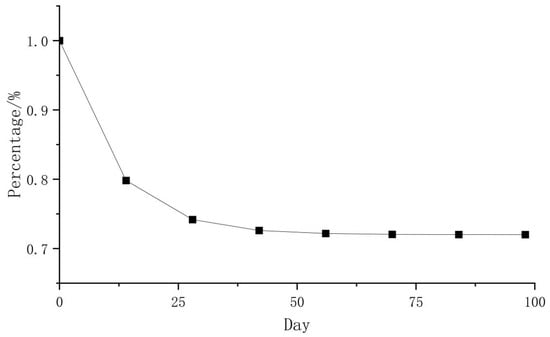
Figure 18.
Grope B percentage degradation equation.
By applying the degradation ratio formula of as an environmental degradation coefficient multiplied by the tensile stress of the CFRP, the degradation of CFRP tensile stress resulting from the deterioration of the CFRP–concrete interface in a hygrothermal marine environment is given as follows:
According to the standard GB 50608-2020 [37] and the failure mode of the CFRP-strengthened RC beams in Ref. [38], the height of the concrete compression zone of the CFRP-strengthened RC beam satisfies , where is the distance from the compressive reinforcement to the compressive edge of the concrete. Correspondingly, the flexural capacity of the CFRP-strengthened RC beams subjected to 5d, 10d, 15d, 30d, and 60d of hygrothermal environmental attacks is simplified as follows:
where is the cross-sectional design bending moment (kN · m); is the yield strength of the tensile reinforcements (N/mm2); is the areas of tensile reinforcements (mm2); is the height from the tensile CFRP section to the compressive concrete edge, generally taken as the overall height of the section (mm); is the distance from the centroid of tensile reinforcement to the compressive edge (mm); is the cross-sectional area of CFRP (mm2).
When the beam reaches the ultimate flexural limit state, the CFRP tensile strain in Equation (4) is taken as the minimum value of Equation (8):
where is the effective tensile strain in the CFRP when the concrete compressive edge reaches the ultimate compressive strain; is the effective tensile strain in the CFRP at interfacial debonding (should not be less than ); is the tensile strength of the CFRP.
As mentioned above, because the CFRP-strengthened RC beams in Ref. [38] failed in the initial yielding of the tensile reinforcements followed by debonding of the CFRP, the height of the concrete compression zone satisfied , and the concrete at the compressive was assumed to be = 0.002, the effective tensile strain in the CFRP is calculated by the following formulas [37]:
where is width of the RC beam; is the yield strength of the compressive reinforcements (N/mm2); is the areas of the compressive reinforcements (mm2).
For the in Equation (8), according to standard GB 50608-2020 [37], the value must satisfy and can be calculated by the following formulas:
where is thickness of the composite sheet (mm); is the development length of the CFRP, extending from the section of full utilization to the cut-off point (mm); is the width influence coefficient of the CFRP; is the width of the CFRP (mm); is the design value of the concrete tensile strength (N/mm2).
5.3. Predicting Results and Discussion
For the CFRP-strengthened RC beam test specimens shown in Figure 17 and Table 7, = 37 mm, = 16.7 mm2. The minimum tensile strain in the CFRP determined by Equation (8) = 0.01198. The predicted flexural capacities Fu and experimental flexural capacities Ft of the CFRP-strengthened RC beams are shown in Table 7. As can be seen from Table 7, the predicted values were approximately 0.8 to 0.9 times the experimental values.
The discrepancies between the predicted and experimental flexural capacities can be attributed to two primary reasons: (1) the predictive formula we employed is derived from a design code, which inherently incorporates safety factors and simplifying assumptions, leading to conservative estimates; (2) there were inevitable minor differences between the exact environmental exposure conditions in our experiments and those assumed in the theoretical model, leading to variations in the applied degradation rate.
It is worth noting that even the original theoretical model presented in Ref. [39] reported a 10% deviation from its experimental values, which is considered acceptable in this field. The proposed model in the present study, which yields results on the conservative (safe) side, aligns with this expected level of variation.
Applying the degradation results derived from circular surfaces to the planar strengthened RC beam experiments was consistent with the findings in Section 3.1, where the CFRP–concrete bond strength on circular surfaces was observed to be 20–22% lower than that on planar surfaces. This indicates that the surface bond strength degradation curve for circular members in hygrothermal environments exhibits a similar degradation amplitude to that for planar surfaces under comparable conditions. Thus, the degradation curve for circular interfacial bond strength in hygrothermal marine environments, as derived from pull-off tests, has been validated. This curve can be applied to other similar hygrothermal environments to estimate the degradation of CFRP–concrete bond strength by predicting the degraded stress provided by the CFRP based on the interfacial bond strength deterioration.
6. Conclusions
In this study, pull-off tests were carried out to investigate the CFRP–concrete interfacial performance of cylindrical concrete specimens subjected to different exposures to simulated hygrothermal marine environmental attacks (3 days in a 50 °C salt spray environment followed by 4 days of seawater immersion). The deterioration mechanism and failure modes of the CFRP–concrete bond behavior in such environments were analyzed. On the basis of the test results, equations describing the CFRP–concrete interfacial bond degradation on a circular concrete surface were proposed and validated. The following conclusions can be drawn:
- Pull-off test results indicate that the bond strength at the CFRP–concrete circular interface is approximately 21% lower than that at the planar interface. Cylinder concrete specimens allow for more measurement points and reduce the inhomogeneity of interfacial bond strength.
- In CFRP-wrapped cylindrical concrete specimens, surface grinding before CFRP application increases the CFRP–concrete bond strength by 33% and delays the occurrence of bond failure. Under hygrothermal marine conditions, the epoxy resin exhibits both plasticization and post-curing effects, leading to an initial decline followed by a partial recovery in bond strength. While the average bond strength remains relatively stable in the early stages, the variability of pull-off data increases significantly in later stages, indicating that evaluation should not rely solely on average strength values.
- After 28 days of exposure to the marine environment, partial mixed failure modes of the CFRP–concrete interfacial zones begin to appear in pull-off tests. With prolonged exposure, the dominant failure modes of the CFRP–concrete interfacial zones change from cohesive concrete failure to mixed failure.
- The average bond strength curve is not suitable for characterizing interfacial degradation under hygrothermal marine conditions. By categorizing test data based on initial bond strength, interfacial degradation models were established using pull-off test results. A nonlinear exponential curve was fitted to the data (R2 = 0.78) and its applicability was validated through flexural tests of RC beams under similar environmental conditions.
For marine concrete structures with restoration value, external CFRP wrapping is recommended as an effective strengthening method. This not only retards chloride ion penetration but also protects the reinforcing bars in the concrete substrate from corrosion, thereby extending the service life of the RC structures. In practical engineering applications, the following testing protocol is proposed to ensure the durability of CFRP-strengthened marine concrete structures:
- (1)
- Conduct bond strength measurements on 15 points per structural member, with a minimum of two representative members tested each time (resulting in a total of no fewer than 30 measurement points) to obtain reliable initial bond strength data;
- (2)
- Perform periodic bond strength testing annually after the initial measurement. By comparing the updated data with the derived bond degradation equation, the degree of interfacial bond deterioration can be quantitatively evaluated, providing a scientific basis for timely maintenance or reinforcement interventions.
This study has several limitations that suggest directions for future work. The accelerated aging protocol requires better benchmarking against real marine conditions, and future studies should establish quantitative acceleration factors. The surface roughness characterization should be qualitative, and parameters (e.g., Ra, Rz) must be employed in the subsequent work. The bond strength reduction on curved concrete test specimens, while experimentally confirmed, needs explanation via 3D FE modeling to analyze stress concentrations. The proposed CFRP–concrete interfacial bond strength empirical degradation models require a more fundamental basis obtained by investigating the underlying physicochemical mechanisms and kinetics.
Author Contributions
J.-W.Z.: methodology, software, validation, formal analysis, investigation, data curation, writing—original draft preparation, visualization. X.-H.W.: conceptualization, resources, writing—review and editing, supervision, project administration, funding acquisition. All authors have read and agreed to the published version of the manuscript.
Funding
This research was funded by Shanghai Natural Science Foundation grant number 21ZR1426800.
Data Availability Statement
The data presented in this study are available upon request from the corresponding author.
Acknowledgments
This research was financially supported by the Shanghai Natural Science Foundation (No. 21ZR1426800).
Conflicts of Interest
The authors declare no conflict of interest.
References
- Sun, L.; Wang, C.; Zhang, C. Experimental investigation on the bond performance of sea sand coral concrete with FRP bar reinforcement for marine environments. Adv. Struct. Eng. 2023, 26, 533–546. [Google Scholar] [CrossRef]
- Wei, X.; Xie, S.; Luo, A.; Liu, Y.; Li, Y.; Wu, L. Performance improvement of ecologically friendly ultra-high performance concrete with waste tire recycled steel fiber. Constr. Build. Mater. 2025, 495, 143607. [Google Scholar] [CrossRef]
- Yang, C.; Nan, Z.; Huo, Y. Design, characterisation, and crushing performance of hexagonal-quadrilateral lattice-filled steel/CFRP hybrid structures. Compos. B Eng. 2025, 304, 112631. [Google Scholar] [CrossRef]
- Weng, Y.H.; Hu, Z.J.; Qian, K. Punching shear behavior of full-scaled reinforced concrete slab-column connection after cooling from fire-induced elevated temperature. Eng. Struct. 2025, 334, 120216. [Google Scholar] [CrossRef]
- Huang, H.; Huang, M.; Zhang, W.; Pospisil, S.; Wu, T. Experimental investigation on rehabilitation of corroded RC columns with BSP and HPFL under combined loadings. J. Struct. Eng. 2020, 146, 04020157. [Google Scholar] [CrossRef]
- Shrestha, B.; Abdulazeez, M.M.; ElGawady, M.A. Comparative study of interfacial bond strength of steel H-pile with ultra- high performance and polymer concrete jacket. Eng. Struct. 2025, 343, 120976. [Google Scholar] [CrossRef]
- Gamage, J.C.P.H.; Al-Mahaidi, R.; Wong, M.B. Integrity of CFRP-concrete bond subjected to long-term cyclic temperature and mechanical stress. Compos. Struct. 2016, 149, 423–433. [Google Scholar] [CrossRef]
- Korkees, F. Moisture absorption behavior and diffusion characteristics of continuous carbon fiber reinforced epoxy composites: A review. Polym-Plast. Technol. Mater. 2023, 62, 1789–1822. [Google Scholar] [CrossRef]
- Liew, J.X.; Zhang, P.; Kai, M.F.; Dai, J.G. An experimental study of the moisture-induced degradation characteristics of GFRP-concrete interface. Mater. Design. 2025, 255, 114183. [Google Scholar] [CrossRef]
- Bhuyan, M.K.; Bhuyan, M.S.; Rodríguez-Dévora, J.I.; Yanez, M. Delamination behavior of bidirectional S2 glass epoxy laminated composite due to combined moisture and temperature cyclic loading. J. Compos. Mater. 2013, 47, 3421–3432. [Google Scholar] [CrossRef]
- Ferrier, E.; Rabinovitch, O.; Michel, L. Mechanical behavior of concrete–resin/adhesive–FRP structural assemblies under low and high temperatures. Constr. Build. Mater. 2016, 127, 1017–1028. [Google Scholar] [CrossRef]
- Firmo, J.P.; Correia, J.R.; Pitta, D.; Tiago, C.; Arruda, M.R.T. Experimental characterization of the bond between externally bonded reinforcement (EBR) CFRP strips and concrete at elevated temperatures. Cem. Concr. Compos. 2015, 60, 44–54. [Google Scholar] [CrossRef]
- Böer, P.; Holliday, L.; Kang, T.H.K. Independent environmental effects on durability of fiber-reinforced polymer wraps in civil applications: A review. Constr. Build. Mater. 2013, 48, 360–370. [Google Scholar] [CrossRef]
- ICC Evaluation Service. Acceptance Criteria for Concrete and Reinforced and Unreinforced Masonry Strengthening Using Externally Bonded Fiber-Reinforced Polymer (FRP) Composite Systems; AC125; ICC: Whittier, CA, USA, 2007. [Google Scholar]
- Blackburn, B.P.; Tatar, J.; Douglas, E.P.; Hamilton, H.R. Effects of hygrothermal conditioning on epoxy adhesives used in FRP composites. Constr. Build. Mater. 2015, 96, 679–689. [Google Scholar] [CrossRef]
- Cromwell, J.R.; Harries, K.A.; Shahrooz, B.M. Environmental durability of externally bonded FRP materials intended for repair of concrete structures. Constr. Build. Mater. 2011, 25, 2528–2539. [Google Scholar] [CrossRef]
- Al-Tamimi, A.K.; Hawileh, R.A.; Abdalla, J.A.; Rasheed, H.A.; Al-Mahaidi, R. Durability of the bond between CFRP plates and concrete exposed to harsh environments. J. Mater. Civil. Eng. 2015, 27, 04014252. [Google Scholar] [CrossRef]
- Silva, M.A.G.; Biscaia, H.C.; Marreiros, R. Bond-slip on CFRP/GFRP-to-concrete joints subjected to moisture, salt fog and temperature cycles. Compos. Part. B Eng. 2013, 55, 374–385. [Google Scholar] [CrossRef]
- Hassan, S.A.; Gholami, M.; Ismail, Y.S.; Sam, A.R.M. Characteristics of concrete/CFRP bonding system under natural tropical climate. Constr. Build. Mater. 2015, 77, 297–306. [Google Scholar] [CrossRef]
- Gholami, M.; Mohd Sam, A.R.; Marsono, A.K.; Tahir, M.M.; Faridmehr, I. Performance of steel beams strengthened with pultruded CFRP plate under various exposures. Steel Compos. Struct. 2016, 20, 999–1022. [Google Scholar] [CrossRef]
- Abanilla, M.A.; Li, Y.; Karbhari, V.M. Durability characterization of wet layup graphite/epoxy composites used in external strengthening. Compos. Part. B Eng. 2005, 37, 200–212. [Google Scholar] [CrossRef]
- Correia, L.; Sena-Cruz, J.; Michels, J.; França, P.; Pereira, E.; Escusa, G. Durability of RC slabs strengthened with prestressed CFRP laminate strips under different environmental and loading conditions. Compos. Part. B Eng. 2017, 125, 71–88. [Google Scholar] [CrossRef]
- Ouyang, Z.; Wan, B. Nonlinear deterioration model for bond interfacial fracture energy of FRP-concrete joints in moist environments. J. Compos. Constr. 2009, 13, 53–63. [Google Scholar] [CrossRef]
- Wang, M.; Xu, X.; Ji, J.; Yang, Y.; Shen, J.; Ye, M. The hygrothermal aging process and mechanism of the novolac epoxy resin. Compos. Part. B Eng. 2016, 107, 1–8. [Google Scholar] [CrossRef]
- Al-Lami, K.; Colombi, P.; D’Antino, T. Influence of hygrothermal ageing on the mechanical properties of CFRP-concrete joints and of their components. Compos. Struct. 2020, 238, 111947. [Google Scholar] [CrossRef]
- Kinloch, A.J. Adhesion and Adhesives: Science and Technology; Chapman and Hall: London, UK, 1987. [Google Scholar]
- Alsuhaibani, E.; Yazdani, N.; Beneberu, E. Experimental and numerical study of CFRP laminate strengthened concrete beams under hygrothermal environment. Adv. Civ. Eng. 2024, 2024, 5472036. [Google Scholar] [CrossRef]
- Fazli, H.; Yassin, A.Y.M.; Shafiq, N.; Teo, W. Pull-off testing as an interfacial bond strength assessment of CFRP-concrete interface exposed to a marine environment. Int. J. Adhes. Adhes. 2018, 84, 335–342. [Google Scholar] [CrossRef]
- Shrestha, J.; Zhang, D.; Ueda, T. Durability performances of carbon fiber-reinforced polymer and concrete-bonded systems under moisture conditions. J. Compos. Constr. 2016, 20, 04016023. [Google Scholar] [CrossRef]
- Long, M.; Djelal, C.; Kesteloot, S.; Bigourdan, B.; Le Gac, P.Y.; Szulc, J. Durability of CFRP concrete bonding in a marine environment. In Proceedings of the European Conference on Composite Materials (ECCM), Venice, Italy, 24–28 June 2012. [Google Scholar]
- Mata, O.R.; Atadero, R.A. Evaluation of pull-off tests as a FRP–concrete bond testing method in the laboratory and field. Pract. Period. Struct. Des. Constr. 2014, 19, 4014001. [Google Scholar] [CrossRef]
- Pallempati, H.; Beneberu, E.; Yazdani, N. Evaluation of external FRP-concrete bond in repaired concrete bridge girders and columns. Innov. Infrastruct. Solut. 2016, 1, 12. [Google Scholar] [CrossRef]
- Shrestha, J.; Ueda, T.; Zhang, D. Durability of FRP concrete bonds and its constituent properties under the influence of moisture conditions. J. Mater. Civ. Eng. 2015, 27, A4014009. [Google Scholar] [CrossRef]
- Grelle, S.V.; Sneed, L.H. Review of anchorage systems for externally bonded FRP laminates. Int. J. Concr. Struct. Mater. 2013, 7, 17–33. [Google Scholar] [CrossRef]
- ASTM D7522/D7522M-21; Standard Test Method for Pull-Off Strength for FRP Laminate Systems Bonded to Concrete or Masonry Substrates. ASTM International: West Conshohocken, PA, USA, 2021.
- Dai, J.G.; Yokota, H.; Iwanami, M.; Kato, E. Experimental investigation of the influence of moisture on the bond behavior of FRP to concrete interfaces. J. Compos. Constr. 2010, 14, 834–844. [Google Scholar] [CrossRef]
- Ascione, L.; Caron, J.F.; Godonou, P.; van IJselmuijden, K.; Knippers, J.; Mottram, T.; Oppe, M.; Sorensen, M.G.; Taby, J.; Tromp, L.; et al. Prospect for New Guidance in the Design of FRP; EC Joint Research Centre: Ispra, Italy, 2016. [Google Scholar]
- GB 50608-2020; Technical Standard for Fiber Reinforced Polymer (FRP) in Construction. China Planning Press: Beijing, China, 2020.
- Jiang, S.; Yao, G.; Liu, C.; Liu, X. Flexural behavior of reinforced concrete beams strengthened with carbon fiber reinforced polymer under hydrothermal environment. J. Southwest JiaoTong Uuiv. 2020, 55, 175–183. [Google Scholar]
Disclaimer/Publisher’s Note: The statements, opinions and data contained in all publications are solely those of the individual author(s) and contributor(s) and not of MDPI and/or the editor(s). MDPI and/or the editor(s) disclaim responsibility for any injury to people or property resulting from any ideas, methods, instructions or products referred to in the content. |
© 2025 by the authors. Licensee MDPI, Basel, Switzerland. This article is an open access article distributed under the terms and conditions of the Creative Commons Attribution (CC BY) license (https://creativecommons.org/licenses/by/4.0/).