Abstract
Suction anchors are widely used in marine engineering because of their easy installation, cost-effectiveness, and excellent load-bearing capacity. However, existing research on their bearing capacity has primarily focused on homogeneous soils, which fails to adequately reflect the actual bearing capacity of layered seabed soils. Therefore, this study conducted a series of numerical simulations to investigate the pullout bearing capacity of suction anchors subjected to inclined loads in upper-stiff–lower-soft layered clay. By considering the clay strength (Sum/kD) and soil layer thickness ratio (Th/L, Tc/L), this study systematically explores the influence of the optimal centerline loading depth (Zcl,opt), uniaxial ultimate bearing capacity (Hult and Vult), and the VH failure envelope of suction anchors. The results indicate that the layer thickness ratio Th/L of lightly overconsolidated clay (LOC) is the key factor influencing the Zcl,opt and ultimate bearing capacity Hult and Vult. An increase in Th/L significantly enhances the pullout resistance of suction anchors, which primarily results from the combined enhancement effect of lateral friction resistance and end resistance at the anchor–soil interface. The layered clay has a distinct influence on the horizontal and vertical bearing capacities of suction anchors. Based on the results of parameter analysis, a conservative analytical expression for the lower bound of the VH failure envelope curve is further proposed. The research conclusions provide a theoretical basis and engineering practice guidance for the optimized design and safety assessment of suction anchors in layered soil.
1. Introduction
Suction anchors typically refer to cylindrical structures that are closed at the top and open at the bottom, commonly constructed of steel or concrete [1,2]. Its diameter is typically 3–7 m, with wall thickness ranging from 25 to 75 mm, and the L/D is typically between 1 and 10 [3]. Suction anchors are widely used in coastal floating platforms, offshore wind turbine foundations, and deepwater projects due to their rapid installation, low cost, high load-bearing capacity, and minimal disturbance to seabed soil layers [4,5]. During the installation of suction anchors, the anchors are initially driven into the seabed soil using their own weight. Subsequently, water is pumped out through the suction holes at the top of the anchor, which creates a pressure differential between the interior and exterior of the anchor. This pressure differential forces the anchor to continue driving into the soil. When the top cover of the suction anchor makes contact with the seabed soil, the anchor is considered fully penetrated [6,7].
In actual engineering environments, offshore structures inevitably experience the effects of waves, wind, and currents [8,9]. Since the load must be transmitted to the suction anchor via the suspension chain and mooring chain, the suction anchor is continuously subjected to inclined loads [10]. The bearing mechanism of suction anchors subjected to inclined pullout loads differs from that of suction anchor foundations bearing vertical loads at the top. The schematic diagram of the suction anchor mooring system is shown in Figure 1. The loading angle and padeye location alter the failure mode of suction anchors [11]. Keaveny et al. [12] conducted prototype tests on a series of suction anchors installed in clay and applied mooring forces to the padeyes of the anchors below the mud surface. The test results indicate that when the mooring force is applied at the midpoint below the mud surface of the suction anchor, the corresponding ultimate bearing capacity is twice that when applied at the mud surface. Newlin [13] suggested that when mooring forces are applied below the optimal padeye position, the top of the suction anchor tilts away from the mooring force direction upon failure. In this case, the failure mode is not pullout failure but rotation within the soil. The suction anchor can obtain its maximum bearing capacity only when the anchor undergoes translational displacement. Therefore, the loading angle and padeye are critical factors affecting suction anchors.
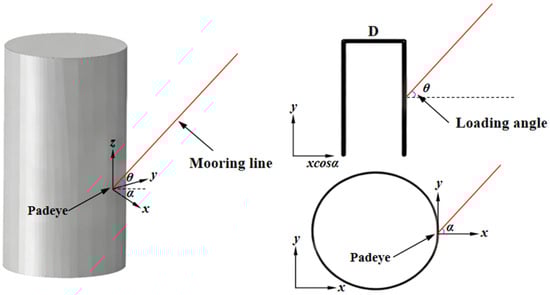
Figure 1.
Schematic diagram of suction anchor mooring.
To explore the ultimate bearing capacity of suction anchors under inclined loads, numerous studies have been conducted through theoretical analysis, numerical simulation, and physical testing. Current research primarily focuses on suction anchors in homogeneous soil. Wang et al. [14] conducted load-controlled model tests on the ultimate bearing capacity of suction anchors in soft clay and analyzed the effects of loading direction on failure modes and ultimate bearing capacity. The test results indicate that the bearing capacity of suction anchors is influenced by the loading direction. The reverse bearing capacity of the soil layer below the anchor base is a key factor affecting the ultimate bearing capacity of suction anchors. Zhang et al. [15] investigated the effect of cutting grooves on the ultimate bearing capacity of suction anchors in normally consolidated clay through numerical simulation methods. Kim et al. [16] investigated the behavior of suction anchor foundations installed in cohesionless soil under horizontal loading through numerical simulation. They conducted parametric studies on different length-to-diameter ratios and padeye positions of the suction anchors. The horizontal bearing capacity of the suction anchors was estimated, and soil stress distribution was analyzed under loading applied at the optimal padeye position. Existing studies on the bearing capacity of suction anchors have primarily focused on single homogeneous soil layers, which do not account for the actual layered characteristics of soil masses [17,18]. However, under the influence of geological movements and sedimentation processes, the actual seabed typically exhibits natural layering or anisotropic properties along the depth direction. The characteristics of such layered soil differ significantly from those of the current single-layer homogeneous soil layers studies [19,20]. In natural layered soils, a typical layered soil structure occurs where stronger soil layers overlie weaker layers [21]. For example, in the Bohai oil and gas fields off of China, the seabed exhibits a layered structure with upper-stiff–lower-soft layers depending on factors such as estuarine sediment transport patterns and tidal currents [22,23]. Additionally, in areas such as the Gulf of Guinea, the Bass Strait off southeastern Australia, and the Joa oil field in the North Sea, the seabed also contains hard soil layers with significantly greater strength than the underlying soil [24,25]. Furthermore, existing design guidelines for piles in layered soils primarily employ the equivalent lateral friction coefficient of the piles and the p–y curve method for lateral friction resistance. This approach is unsuitable for predicting the pullout resistance of suction anchors in layered soils. Existing guidelines, such as those from the American Petroleum Institute (API) [26] and DNV [27], typically assume homogeneous and uniform soil properties. Applying these existing guidelines to predict bearing capacity under layered soil conditions may be overly conservative. Therefore, it is important to fully consider the influence of layered soil properties to gain a deeper understanding of the pullout resistance capacity of suction anchors.
Based on the above-mentioned research status, this study aims to investigate the ultimate bearing capacity of suction anchors in upper-stiff–lower-soft layered clay. To analyze the bearing capacity of suction anchors under inclined loads, numerical simulation methods were employed. Considering variations in clay strength (Sum/kD) and layer thickness ratios (Th/L, Tc/L, Tn/L), the ultimate bearing capacity of suction anchors subjected to inclined loads in layered clay (lightly overconsolidated clay (LOC, thickness = Th), in normally consolidated clay (NC, thickness = Tc), and in low-strength normally consolidated clay (LNC, thickness = Tn)) was investigated. The primary research content includes (1) determining the optimal centerline loading depth Zcl,opt in layered clay; (2) obtaining the corresponding uniaxial ultimate bearing capacities Hult and Vult; (3) quantifying the suction anchor VH failure envelope under inclined loading and deriving an analytical expression for its lower-bound solution.
2. Numerical Modeling
2.1. Geometry and Mesh
By referring the studies of Kim et al. [28] and Fu et al. [29], the numerical simulation model selected the suction anchor diameter D = 5 m and a depth of embedment of L = 7.5 m, with L/D = 1.5 and a thickness of t = 50 mm. The selected suction anchor dimensions are commonly adopted in engineering practice [30,31]. As shown in Figure 2a, the suction anchor is installed in layered clay. As the stiffness of suction anchors and soil differs significantly, suction anchors are typically treated as rigid bodies to improve computational efficiency. This method is widely applied in offshore geotechnical engineering [32,33]. The suction anchor is modeled using rigid materials with a density of ρ = 6800 kg/m3, an elastic modulus of E = 210 GPa, and a Poisson’s ratio of ν = 0.3. An inclined load is applied by setting a reference point on the suction anchor.
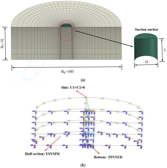
Figure 2.
Schematic diagram of the numerical model: (a) Model mesh partitioning; (b) Model constraint settings.
In this study, a three-dimensional finite element model was constructed using the commercial software ABAQUS 2020. The suction anchor and soil mass were modeled using three-dimensional eight-node solid elements (C3D8H). Due to load symmetry, only half of the soil mass was modeled to improve computational efficiency. The minimum mesh size for the model was 0.02 D. Based on existing research and the sensitivity analysis of mesh sizes, the selected minimum mesh size was reasonable [34,35]. The length and height of the soil were BH = 10 D and BV = 3 L, respectively, with the suction anchor positioned at the center of the soil model. The model dimensions were selected sufficiently large to eliminate the influence of boundary effects [18,36]. The relevant constraints on the soil are shown in Figure 2b.
2.2. Soil Parameters and Interface Properties
The clay in this study is treated as an elastoplastic material, adhering to the Tresca yield criterion and associated flow rules [26]. The Poisson’s ratio of the clay is ν = 0.49, which is used to simulate undrained conditions where volume remains constant. The undrained shear strength of the clay is satisfied:
where represents the undrained shear strength of the soil at the mud surface, represents the gradient of clay strength with depth, and represents the depth below the mud surface. The soil elastic modulus is taken as E = 500 Su, and the normalized parameter Sum/kD is used to evaluate the influence of soil properties on bearing capacity. Based on relevant studies and geological exploration reports (Sum/kD = 0, 0.4, 0.67, and 1.0 [37,38,39,40]), the relevant parameters of the clay are shown in Table 1. The selection of clay parameters is based on the summary of idealized seabed profiles for offshore wind farms in numerous regions by Cerfontaine et al. [41]. The chosen clay strength encompasses both low-strength and high-strength clays. The numerical simulation tests for suction anchors are outlined in Table 2.

Table 1.
Clay parameters.
Table 2.
The experimental setup for the suction anchor numerical simulation test.
To investigate the bearing capacity of suction anchors in upper-stiff–lower-soft layered clay under inclined loading, the soil in this study was divided into three layers. The first layer consisted of LOC with Sum/kD = 1.0 and layer thickness ratios Th/L = 0.5, 0.75 and 1.25. The second layer comprised either NC or LOC, with Sum/kD values of 0.4, 0.67, and 1.0, and layer thickness ratios Tc/L = 0.5, 0.75, and 1.25. The third layer consisted of LNC, with Sum/kD = 0 and a soil layer thickness ratio Tn/L = (3 L − Th − Tc)/L. The relevant parameters were obtained by referring to related research and geological exploration reports. Regarding the bearing capacity of suction anchors in clay, due to the low permeability coefficient of clay, numerous studies have assumed the soil to be in undrained conditions [42,43,44].
2.3. Details of Analysis and Loading Methods
The finite element modeling process includes the following steps:
- (1)
- The model construction and meshing stage: A finite element model of the suction anchor and soil was constructed and meshed. The mesh size for the suction anchor was set to 0.02 D, with a C3D8H mesh type. The soil mesh size was progressively refined, with smaller mesh sizes closer to the suction anchor, and the minimum mesh size was 0.02 D.
- (2)
- The initial geostress equilibrium stage: The finite element model was assembled, and the geostress equilibrium and loading analysis steps were set up. The geostress equilibrium analysis was performed first. In this stage, only the soil mass was subjected to geostress equilibrium analysis, and the suction anchor was treated as void space. In the initial geostress equilibrium stage, the anchor–soil interface contact was not activated.
- (3)
- The contact activation stage: After the soil stress equilibrium is established, the anchor–soil interface contact is activated. This means the penetration process of the suction anchor is disregarded, and the suction anchor is considered to be in the “in-place” state.
- (4)
- The load application stage: A reference point, RP, is established at the suction anchor to apply the inclined load. The inclined pullout load is applied under displacement control, with a maximum allowable displacement of 0.2 D.
The tangent method was employed to determine the uniaxial bearing load capacity, based on the study of Long et al. [45], for which no distinct yield value was observed when the load-displacement curve reached its maximum displacement. When the suction anchor moves horizontally or vertically without rotation, the uniaxial bearing capacity is equivalent to the uniaxial ultimate bearing capacity Hult and Vult. The complete VH failure envelopes for the suction anchor can be obtained through sweep analysis, reverse sweep analysis, and probe analysis, which have been widely applied [46,47,48].
As shown in Figure 3, when the suction anchor moves horizontally under inclined loading without rotation, the inclined load can be simplified into a horizontal force H, a vertical force V, a constraining moment M, and mooring angle . By applying the principle of moment equilibrium, the optimal padeye depth Zpad,opt at the corresponding angle and the optimal centerline loading depth Zcl,opt can be obtained, which satisfy the equation:
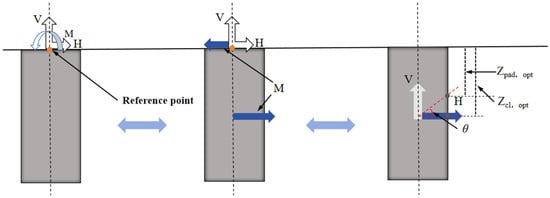
Figure 3.
The schematic diagram of the optimum centerline loading depth for the suction anchor.
By displacement control the inclined load was applied at the reference point set at the top center of the suction anchor, and the accuracy of the test results has been extensively validated [49]. The ultimate bearing capacity of suction anchors was defined as the load capacity corresponding to translational motion without rotation. Therefore, a reference point “PR” was established at the top center of the suction anchor to restrict rotation. By applying the corresponding inclined load, the corresponding ultimate bearing capacity was obtained.
3. Model Validation
To validate the accuracy of the constructed numerical model, the numerical simulation results of suction anchors under inclined loading were compared with existing experimental results, as shown in Figure 4. It can be seen from Figure 4a that for NC with Su = 1.25 z and L/D = 1.5, the numerical simulation results show excellent consistency with test results from Supachawarote [50] and the experimental results from the Norwegian Geotechnical Institute (NGI), the Offshore Technology Research Center (OTRC), and the Center for Offshore Foundation Systems (COFSs) [30,51]. The VH envelope obtained from the numerical model closely matches their findings, which indicates that the numerical model developed in this study can effectively reproduce the pullout behavior of suction anchors in clay.
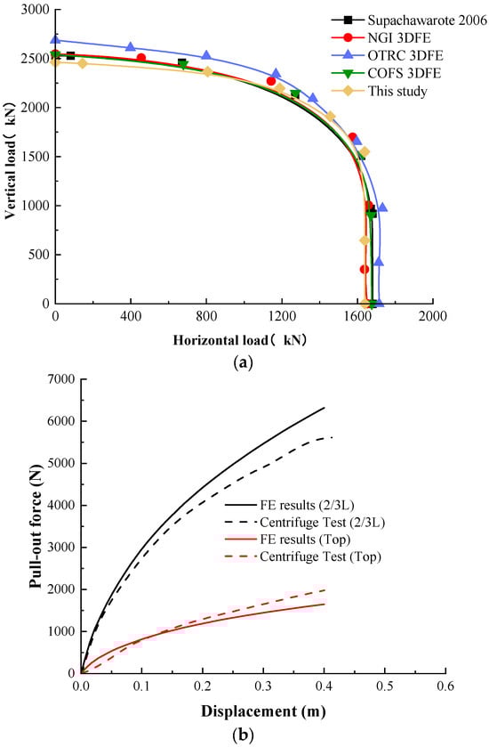
Figure 4.
Model validation results: (a) Validation results for clay [50]; (b) Validation results for silty sand [28].
Furthermore, the accuracy of the constructed numerical simulation model was further validated by referencing centrifuge test data and finite element modeling results for non-cohesive soils from Kim et al. [28]. The loads were applied at the top of the suction anchor and below the mud surface at Zpad = 2/3 L, with Cu = 7 kPa, the internal friction angle φ = 32°, and the dilation angle ψ = 8°. The selection of relevant parameters strictly followed those used in the centrifuge tests and the finite element model. The corresponding comparison results are shown in Figure 4b, which shows that the constructed numerical model can effectively characterize the bearing capacity of the suction anchor.
4. Results of Numerical Analyses
4.1. Optimum Centerline Loading Depth Zcl,opt
The optimal centerline loading depth Zcl,opt is the key factor determining whether the suction anchor undergoes translational or rotational motion under inclined loading. When the inclined load vector applied to the suction anchors padeye passes through Zcl,opt, the suction anchors move horizontally under the inclined load without rotation. At this point, the inclined load corresponds to the maximum pullout force at the given mooring angle. When the inclined load vector applied to the anchor padeye deviates from Zcl,opt, the suction anchor will rotate forward or backward during the pullout process, correspondingly reducing the pullout resistance of the suction anchor. Therefore, Zcl,opt is an indicator reflecting the pullout resistance capacity and failure mode of the suction anchor under corresponding soil parameter conditions. In engineering design, the location of Zcl,opt must be prioritized for determination.
Figure 5 shows the influence of different soil mechanical parameters and layer thickness on the optimal centerline loading depth Zcl,opt for layered clay. It can be seen that the LOC thickness ratio Th/L is the key factor controlling Zcl,opt. Taking Sum/kD = 0.4 as an example, when Th/L = 0.5, half of the suction anchor is embedded in the LOC layer, with Zcl,opt = 0.65. With the increase in Th/L to 0.75 and 1.25, the upper portion of the suction anchor contributes more lateral friction resistance due to the increased thickness of the LOC layer. To balance the moments, the suction anchors Zcl,opt shift downward, with the corresponding values Zcl,opt being 0.67 and 0.71, respectively. When Th/L > 1, the suction anchor is fully embedded in the LOC layer. The values of Zcl,opt remain nearly unchanged for different Sum/kD and Tc/L, as the high strength of the LOC soil dominates the pullout resistance. When Th/L = 0.5 and Tc/L = 0.5, the suction anchor end is located between the NC layer and the LNC layer interface. It can be observed that the variation of Zcl,opt at this point is still influenced by the higher-strength clay within the suction anchor, which means that the impact of high-strength clay on Zcl,opt is significantly greater than that of low-strength clay.
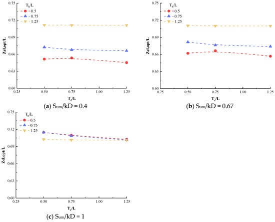
Figure 5.
The effect of layered soil thickness on the optimal centerline loading depth Zcl,opt.
4.2. Uniaxial Ultimate Bearing Capacity (Hult and Vult)
The uniaxial ultimate bearing capacity (Hult and Vult) represents the pullout resistance of the suction anchors when subjected to horizontal or vertical pullout forces without rotation. In numerical simulations, the uniaxial ultimate bearing capacity equals the integral of the ultimate lateral friction resistance along the anchorage depth. Based on the above principles, the effects of suction anchor relative positions (Th/L and Tc/L) and soil strength (Sum/kD) on uniaxial ultimate bearing capacity were quantified. The uniaxial ultimate bearing capacities Hult and Vult of suction anchors under different conditions are shown in Table 3, Table 4 and Table 5.
Table 3.
Uniaxial ultimate bearing capacity Hult and Vult (Sum/kD = 0.4).
Table 4.
Uniaxial ultimate bearing capacity Hult and Vult (Sum/kD = 0.67).
Table 5.
Uniaxial ultimate bearing capacity Hult and Vult (Sum/kD = 1).
As shown in Table 3, Table 4 and Table 5, the LOC thickness ratio Th/L is the core factor determining the uniaxial ultimate bearing capacity. Specifically, the undrained shear strength of LOC is significantly higher than that of NC and LNC. As the embedment length of the suction anchor into the LOC increases, the combined effect of lateral friction resistance and end resistance at the anchor–soil interface becomes more pronounced. Taking Sum/kD = 0.67 and Tc/L = 0.5 as examples, when Th/L increases from 0.5 to 1.25, the corresponding horizontal ultimate bearing capacity Hult of the suction anchor rises from 4182.01 kN to 5096.61 kN, representing an increase of approximately 21.9%. The vertical ultimate bearing capacity Vult increases from 4457.01 kN to 6566.56 kN, representing an increase of approximately 47.3%. This supports the findings of Zhou et al. [18,45], which concluded that the pullout resistance of suction anchors in layered soils is positively correlated with the thickness of the anchor embedded in the higher undrained strength clay layer. As the anchor embedment depth in the higher undrained strength clay layer increases, both lateral friction resistance and end resistance enhance during the anchor–soil interface interaction under pullout forces.
The corresponding displacement contour map (Figure 6) also shows that as Th/L increases from 0.5 to 1.25, the suction anchors experience passive earth pressure on the external wall under horizontal loading, which results in the formation of a passive earth pressure zone. The extent of this passive earth pressure zone is primarily influenced by the length L of the suction anchor. When the suction anchor length remains constant, the horizontal ultimate bearing capacity is primarily influenced by the strength of the clay surrounding the anchor.
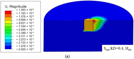
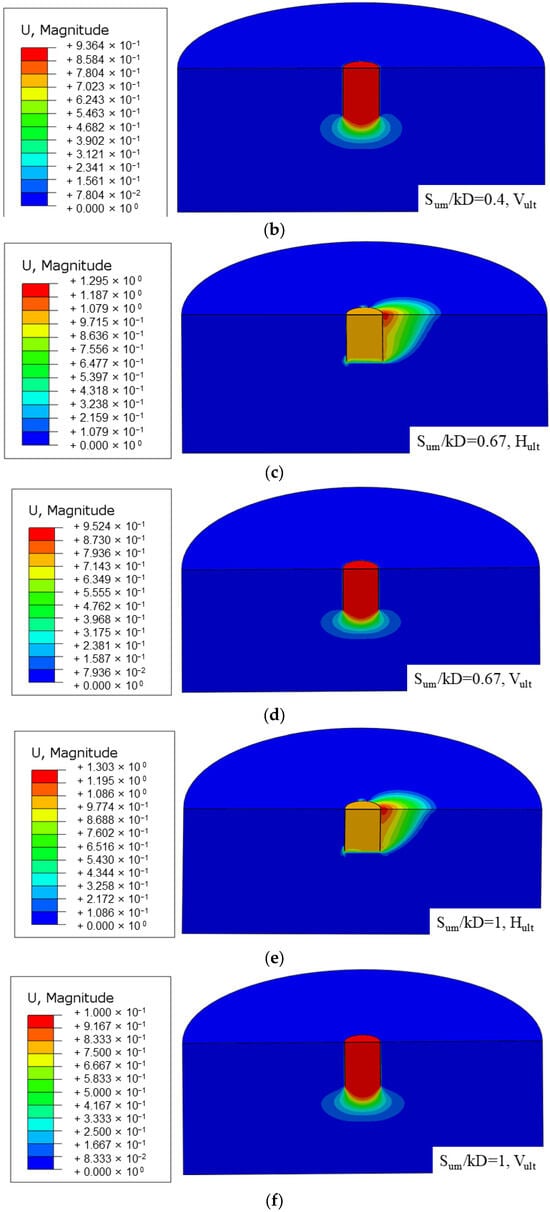
Figure 6.
The displacement contour plots of suction anchors under horizontal/vertical loads (Sum/kD = 0.67,Tc/L = 0.5): (a,b) Th/L = 0.5; (c,d) Th/L = 0.75; (e,f) Th/L = 1.25; the units in the figures are meters.
When subjected to vertical loads, the pullout resistance of suction anchors is primarily composed of the anchor–soil lateral friction resistance and end resistance. As the thickness ratio Th/L of the LOC soil layer increases, Figure 6 shows that the end-resistance influence zone expands. By combining the results in Table 3, Table 4 and Table 5, it can be seen that as Th/L increases, the bearing capacity of the suction anchor improves. Based on the definition of lateral friction resistance, the lateral friction resistance of the suction anchor remains unchanged at this stage. This means that the contribution of end resistance to the vertical bearing capacity of the suction anchor increases, and consequently, the corresponding vertical ultimate bearing capacity Vult increases. The vertical ultimate bearing capacity is primarily influenced by the thickness ratios Th/L and Tc/L.
The layered clay makes the soil strength along the clay surface exhibit non-uniformity. The increase in Sum/kD enhances the uniaxial bearing capacity of layered clay. Taking Th/L = 0.5 and Tc/L = 0.5 as examples, when Sum/kD increases from 0.4 to 1.0, Hult rises from 3990.1 kN to 5017.5 kN, an increase of approximately 25.7%; Vult increases from 4195.2 kN to 5341.32 kN, an increase of approximately 27.3%. The higher the Sum/kD, the greater the overall shear strength of the layered soil, and both the friction resistance and end resistance at the anchor–soil interface increase simultaneously. The soil strength Sum/kD is positively correlated with bearing capacity: the higher the soil strength, the greater the corresponding bearing resistance. The thickness of the LNC soil layer has no significant effect on Hult and Vult. The displacement vector contour plots for layered soil subjected to horizontal/vertical loads are shown in Figure 7.
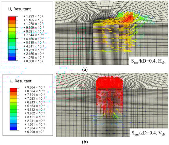
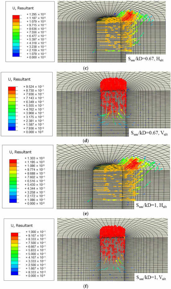
Figure 7.
The displacement vector plots of suction anchors under horizontal/vertical loads (Th/L, Tc/L = 0.5): (a,b) Sum/kD = 0.4; (c,d) Sum/kD = 0.67; (e,f) Sum/kD = 1; the units in the figures are meters.
It can be observed that when the thickness ratios Th/L and Tc/L remain unchanged, the corresponding horizontal/vertical load-displacement vector plots show little variation. This indicates that at this point, the bearing capacity of the suction anchor is primarily influenced by the friction resistance at the anchor–soil interface.
The thickness ratio Tc/L of the NC soil layer has little effect on the horizontal ultimate bearing capacity Hult but significantly affects the vertical ultimate bearing capacity Vult. For example, when Sum/kD = 1.0 and Th/L = 0.5, as Tc/L increases from 0.5 to 1.25, Hult changes little, rising only from 5017.5 kN to 5085.19 kN. Meanwhile, Vult increases from 5341.32 kN to 7211.5 kN, representing an increase of approximately 35.0%. Combining Figure 6 and Figure 7 with the studies by Supachawarote [50], vertical bearing capacity relies more on the accumulated effect of friction resistance at the anchor–soil interface (the accumulation of lateral friction and end resistance). As the strength of the clay in the suction anchorage zone increases, the friction resistance becomes more pronounced. In contrast, horizontal bearing capacity is dominated by the distribution pattern of lateral resistance. The influence of Tc/L on Hult is smaller than that of Th/L and Sum/kD, which leads to a relatively minor overall change in Hult.
When Th/L > 1, which corresponded to the suction anchor being fully embedded in the LOC layer, the horizontal ultimate bearing capacity Hult tended toward stability. Meanwhile, the vertical ultimate bearing capacity Vult still shows a slight increase, which suggests that the vertical bearing capacity is more complexly affected by the coupling of multiple soil layers. The lower soil layers (NC, LNC) still contribute to the end resistance. As the end resistance represents the force between the suction anchor end and the soil it contacts, it can also be seen from Figure 6 that an end-resistance influence zone exists. This means that the end resistance of the suction anchor is related to the strength of the soil within a certain area around the end of the suction anchor.
4.3. The VH Failure Envelopes
The VH failure envelopes for layered soil are shown in Figure 8. By dimensionless processing of horizontal and vertical bearing capacities using H0/γ′D and V0/γ′D, respectively, the effects of parameters such as suction anchor dimensions and soil weight are eliminated.
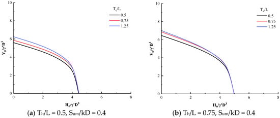
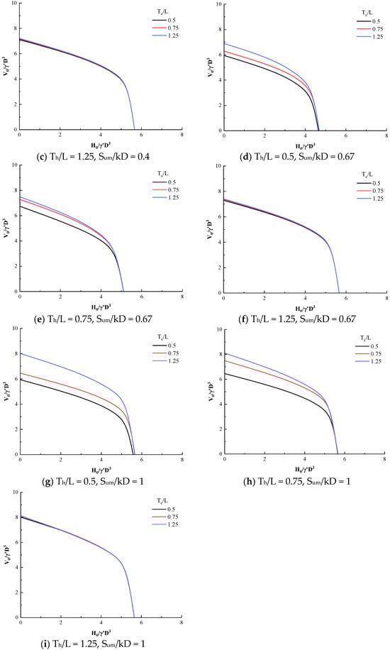
Figure 8.
The results of VH failure envelopes: (a–c) Sum/kD = 0.4, Th/L = 0.5, 0.75, 1.25; (d–f) Sum/kD = 0.67, Th/L = 0.5, 0.75, 1.25; (g–i) Sum/kD = 1, Th/L = 0.5, 0.75, 1.25.
As shown in Figure 8, with the increase in the LOC layer thickness ratio Th/L (from 0.5 to 1.25), the horizontal bearing capacity of the VH failure envelopes significantly increases under the same vertical load. This indicates that the total area of the VH failure envelopes expands, which means that the corresponding combined uniaxial bearing capacity improves. The LOC soil layer exhibits relatively high strength. As the thickness ratio Th/L increases, the contact area between the suction anchor and the high-strength clay expands. This allows the anchor–soil interface to provide more uniform and substantial lateral friction resistance. Consequently, when horizontal loads increase, the attenuation of vertical loads becomes more gradual. The research findings align with the conclusions of Zhao et al. [52], indicating that the embedment length of suction anchors in high-strength soil layers is positively correlated with the combined bearing capacity.
The VH failure envelopes in layered clay exhibit asymmetry, which indicates that layered clay has a distinct influence on the horizontal and vertical bearing capacities of suction anchors. The horizontal friction resistance of the suction anchors dominates when horizontal loads dominate, with the thickness of the LOC layer determining the horizontal bearing capacity. When vertical loads dominate, the friction resistance at the anchor–soil interface and the end resistance play key roles, while the vertical bearing capacity is influenced by both the LOC and the underlying NC and LNC layers. By combining the results with Figure 8c,f,i, it can also be observed that when Th/L = 1.25, the suction anchor is fully embedded in the LOC layer. As the strength of the NC and LNC layers varies, the horizontal pullout bearing capacity of the suction anchor remains nearly constant, while the corresponding vertical pullout bearing capacity slightly increases with the increase in the strength of the NC and LNC layers.
To visually represent the relative shape of the VH failure envelope, the results can be normalized based on the uniaxial bearing capacity H0 and V0. Extensive research indicates that the only lower bound solution of the VH failure envelope can be observed through relevant processing, which shows that the normalized VH failure envelope is independent of soil layer thickness and soil properties [53,54]. This conservative solution method allows the yield envelope in the VH envelope to be obtained simply by scaling H0 and V0. Based on previous research findings and regression analysis, the lower bound of the VH failure envelope, as shown in Figure 9, and can be expressed as follows:
where represents the normalized vertical bearing capacity and represents the normalized horizontal bearing capacity. The exponent 1/0.85 indicates that the vertical bearing capacity reduces the capacity of the horizontal bearing capacity. Meanwhile, the ultimate bearing capacity of the suction anchors installed in layered clay can be obtained by multiplying the corresponding ultimate bearing capacities Hult and Vult by Equation (4).
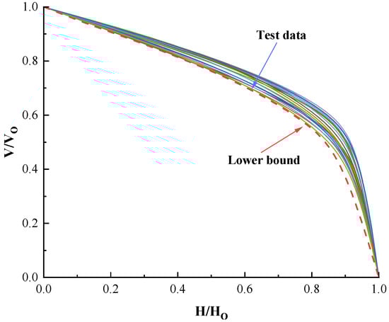
Figure 9.
The normalized VH failure envelope.
5. Discussion
In this paper, the bearing capacity of suction anchors subjected to inclined loads in upper-stiff–lower-soft layered clay is systematically investigated. The numerical simulation results indicate that the clay strength Sum/kD and the thickness ratio T/L are the core factors determining the bearing capacity of layered clay. To investigate the difference in bearing capacity of suction anchors in layered clay and homogeneous clay under inclined loading, the same numerical model shown in Figure 1 was employed to analyze the pullout bearing capacity of suction anchors for different clay strengths Sum/kD (Clay A to Clay D), as listed in Table 1. The optimum centerline loading depth, uniaxial ultimate load capacity, and VH failure envelopes under the corresponding operating conditions were investigated.
It can be seen from Figure 10 that for homogeneous clay with varying Sum/kD, as the clay strength increases, Zcl,opt decreases from 0.71 to 0.69. The increase in Sum/kD indicates a higher proportion of shear strength near the mud surface, shifting the center of gravity of the anchor shear strength upward. According to the principle of moment equilibrium, to prevent anchor rotation, Zcl,opt shifts slightly upward. Overall, Zcl,opt exhibited little change.
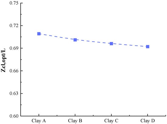
Figure 10.
Optimal centerline loading depth Zcl,opt for suction anchors in homogeneous clay.
Compared with the results in Section 4.1, it can be observed that the homogeneous clay Zcl,opt is solely influenced by Sum/kD, which has a more stable variation pattern. For layered clays, Zcl,opt is primarily affected by the LOC layer, while the influence of the NC and LNC layers on Zcl,opt is masked by the high-strength LOC layer. This indicates that layered soils differ from homogeneous soils in their single correlation of ‘Sum/kD-Zcl,opt,’ with the thickness of high-strength soil layers being the core variable controlling Zcl,opt. By comparing with the findings of Fu et al. [29] for homogeneous clay Zcl,opt, the accuracy of the constructed numerical model can be further validated.
In combination with Figure 11, it can be observed that, as Sum/kD increases, the uniaxial ultimate bearing capacity grows synchronously. However, the rate of increase varies: when Sum/kD rises from 0.4 to 1.0, the horizontal ultimate bearing capacity Hult increases from 2915.65 kN to 5095.8 kN (an increase of approximately 74.8%), whereas the vertical ultimate bearing capacity Vult increases from 3976.02 kN to 7317.5 kN (an increase of approximately 84.0%). The increase in Hult is more pronounced. This difference stems from the distinct mechanisms governing bearing capacity. Horizontal bearing capacity relies on the uniform mobilization of lateral friction resistance throughout the entire anchor length; as Sum/kD increases, lateral friction resistance at all anchor depths rises synchronously. In contrast, because the vertical bearing capacity is simultaneously influenced by end resistance, this also results in a greater increase in the vertical ultimate bearing capacity than in the horizontal ultimate bearing capacity.
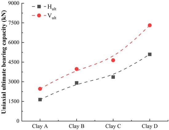
Figure 11.
Uniaxial ultimate bearing capacity Hult and Vult for homogeneous clay.
In comparison with Section 4.2, it is evident that Hult in layered clay is largely unaffected by the thicknesses of the NC and LNC layers. When Tc/L increases from 0.5 to 1.25, Hult remains nearly constant, being controlled solely by the LOC layer thickness Th/L, whereas Vult is influenced by both Th/L and Tc/L. When Tc/L increases to 1.25, Vult increases by approximately 35%. This contrasts with the behavior in homogeneous clay, where both Hult and Vult are governed by a single Sum/kD. Horizontal bearing capacity is more sensitive to the upper high-strength soil layer, while vertical bearing capacity is influenced by the coupled effects of multiple soil layers.
The VH failure envelopes for homogeneous clay are shown in Figure 12. By comparing with Section 4.3, it can be observed that the VH envelopes of layered clay exhibit distinct differences from those of homogeneous clay. Specifically, when the horizontal bearing capacity is high, the envelope retains relatively high vertical bearing capacity, with the LOC layer providing significant lateral friction resistance. Conversely, when the vertical bearing capacity is high, the envelope corresponds to a decrease in bearing capacity, where the anchor tip may be located in the NC or LNC layer, resulting in reduced end resistance.
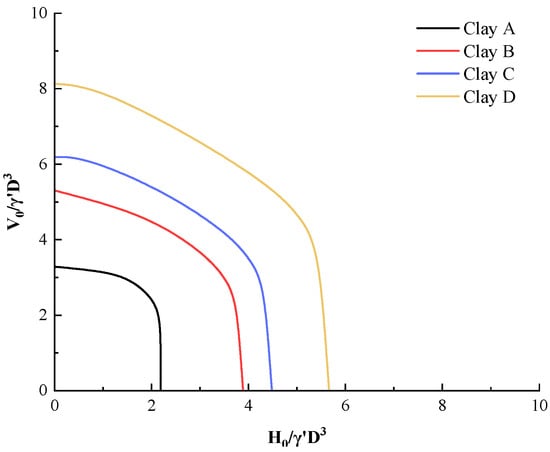
Figure 12.
The VH failure envelopes for homogeneous clay.
A comprehensive analysis reveals significant differences in the pullout resistance of suction anchors in homogeneous clay and layered clay. While extensive research has focused on the bearing capacity of suction anchors in homogeneous clay, it is essential to investigate their pullout resistance in layered clay.
6. Limitations
This study conducted a series of pullout bearing capacity analyses for suction anchors with a commonly used L/D = 1.5 in engineering applications, specifically within upper-stiff–lower-soft clay. It systematically investigated the effects of upper-stiff–lower-soft layered clay on the optimal centerline loading depth Zcl,opt, uniaxial ultimate bearing capacity Hult and Vult, and VH failure envelopes of suction anchors. The findings provide a theoretical basis and practical guidance for optimizing the design and safety assessment of suction anchor foundations in layered clay. However, certain limitations remain.
- (1)
- This paper investigates the pullout bearing capacity of suction anchors subjected to inclined loads in layered clay with upper-stiff–lower-soft. In practical engineering, layered clay exhibits diverse characteristics, such as upper-stiff–lower-soft, upper-soft–lower-hard, soft–hard–soft, and hard–soft–hard, etc. Therefore, based on existing research, a systematic investigation into the bearing capacity of suction anchors in layered clay is necessary.
- (2)
- This paper investigates the pullout bearing capacity of suction anchors with a L/D = 1.5 in layered clay. In practical engineering applications, the L/D of suction anchors varies according to project design (ranging from L/D = 1 to 10). Therefore, further research is required to study the pullout bearing capacity in layered clay under a wide range of L/D.
- (3)
- This paper only systematically analyzes the pullout capacity of suction anchors and does not examine in detail how pullout capacity varies with different padeyes. Further research is needed to analyze the pullout capacity of suction anchors at different padeyes under inclined loads.
Therefore, subsequent research should systematically investigate the bearing capacity of suction anchors under different layered soils (upper-stiff–lower-soft, upper-soft–lower hard, soft–hard–soft, and hard–soft–hard, etc.), varying L/D, and different padeyes locations. By normalizing relevant data, the pullout resistance capacity of suction anchors in different layered soils should be evaluated, and the corresponding design framework based on numerical analysis should be proposed.
7. Conclusions
In this paper, finite element numerical simulations were conducted to investigate the pullout capacity of suction anchors under inclined loading. This study examined the effects of varying soil parameters Sum/kD and layer thickness ratios Th/L and Tc/L on the optimum centerline loading depth Zcl,opt, uniaxial ultimate bearing capacity (Hult and Vult), and VH failure envelope of suction anchors. The main conclusions are as follows.
- (1)
- The layer thickness ratio Th/L of the LOC is the core factor controlling Zcl,opt. When the suction anchor partially embeds into the LOC layer, as the LOC layer thickness increases, the upper portion of the suction anchor contributes more lateral friction resistance. To balance the moments, the suction anchors Zcl,opt shifts downward. When the suction anchor is fully embedded in the LOC soil layer, Zcl,opt depends solely on the parameters of the LOC soil mass.
- (2)
- The thickness ratio Th/L of the LOC soil layer is the core factor determining the uniaxial ultimate bearing capacity, as the undrained shear strength of the LOC layer is significantly higher than that of the NC layer. As the length of the suction anchor embedded into the LOC layer increases, the combined effect of lateral friction resistance and end resistance at the anchor–soil interface becomes more pronounced. The layered soil makes the soil strength along the clay surface exhibit non-uniformity. The increase in Sum/kD enhances the uniaxial bearing capacity of layered clay. The thickness of the NC layer Tc/L, has little effect on the horizontal ultimate bearing capacity Hult but significantly influences the vertical ultimate bearing capacity Vult.
- (3)
- The strength of the LOC soil is relatively high. As the thickness ratio Th/L increases, the contact area between the suction anchor and the high-strength clay expands, providing more uniform and greater lateral friction at the anchor–soil interface. When the horizontal bearing capacity increases, the decrease in vertical bearing capacity becomes more gradual. The lower bound solution for the VH failure envelope of the corresponding layered soil has been obtained.
- (4)
- A comparative analysis of the pullout bearing capacity of suction anchors under inclined loads in layered clay and homogeneous clay reveals that soil layering significantly affects the bearing capacity of suction anchors. In homogeneous clay, the pullout bearing capacity of suction anchors is solely influenced by the soil strength Sum/kD. In contrast, the pullout bearing capacity in layered clay is affected by factors including the soil strength Sum/kD and the soil layer thickness ratio T/L.
Author Contributions
Conceptualization, C.-L.J. and L.-L.L.; Methodology, X.-T.Z., H.-Y.W. and D.-F.F.; Formal analysis, H.-Y.W. and L.-L.L.; Investigation, C.-L.J. and H.-Y.W.; Resources, X.-T.Z. and D.-F.F.; Writing—original draft, C.-L.J. and H.-Y.W.; Writing—review & editing, X.-T.Z., L.-L.L. and D.-F.F.; Visualization, H.-Y.W.; Supervision, L.-L.L.; Project administration, X.-T.Z.; Funding acquisition, L.-L.L. and D.-F.F. All authors have read and agreed to the published version of the manuscript.
Funding
The authors would like to acknowledge the consistent support provided by the National Natural Science Foundation of China (through the grant of No. 52394251), the Natural Science Foundation of Shandong Province (Grant ZR2022YQ54), and the Taishan Scholars Programs. Their support is gratefully acknowledged.
Data Availability Statement
The data presented in this study are available on request from the corresponding author due to privacy.
Conflicts of Interest
Authors Cheng-Liang Ji and Xia-Tao Zhang are employed by the Shandong Electric Power Engineering Consulting Institute Co., Ltd. The remaining authors declare that the research was conducted in the absence of any commercial or financial relationships that could be construed as a potential conflict of interest.
Abbreviations
The following symbols are used in this paper:
| θ | Loading angle |
| BH | Width of horizontal boundary |
| BV | Height of vertical boundary |
| D | The diameter of the suction anchor |
| E | Young’s modulus |
| H | Horizontal load |
| H0 | Horizontal pullout bearing capacity |
| H0/γ′D3 | Dimensionless horizontal pullout bearing capacity |
| Hult | Ultimate horizontal pullout bearing capacity |
| k | Normally consolidated soil clay strength gradient |
| L | Length of suction anchor |
| L/D | Normalized length of suction anchor |
| LNC | Low-strength normally consolidated clay |
| LOC | Lightly overconsolidated clay |
| M | Moment reaction force |
| NC | Normally consolidated clay |
| Su | Clay undrained shear strength |
| Sum | Clay undrained shear strength at mudline |
| Sum/kD | Normalized clay shear strength |
| t | Thickness of suction anchor |
| Th | Thickness of lightly overconsolidated clay |
| Th/L | Normalized thickness of lightly overconsolidated clay |
| Tc | Thickness of normally consolidated clay |
| Tc/L | Normalized thickness of thickness of normally consolidated clay |
| Tn | Thickness of low-strength normally consolidated clay |
| Tn/L | Normalized thickness of low-strength normally consolidated clay |
| V | Vertical load |
| V0 | Vertical pullout bearing capacity |
| V0/γ′D3 | Dimensionless vertical pullout bearing capacity |
| Vult | Ultimate vertical pullout bearing capacity |
| Z | Depth below the mudline |
| Zpad | Depth of the padeye |
| Zcl | Depth of the centerline |
| Zpad,opt | Optimized padeye depth |
| Zcl,opt | Depth of the optimized centerline |
| Zpad,opt/L | Dimensionless optimized depth of the padeye |
| Zcl,opt/L | Dimensionless optimized centerline depth |
| γ′ | Effective unit weight |
| ν | Poisson’s ratio |
References
- Tjelta, T.I. Suction Piles: Their Position and Application Today. In Proceedings of the Eleventh International Offshore and Polar Engineering Conference, Stavanger, Norway, 17–22 June 2001. [Google Scholar]
- Andersen, K.H.; Jostad, H.P. Foundation design of skirted foundations and anchors in clay. In Proceedings of the Offshore Technology Conference, Houston, TX, USA, 3–6 May 1999; OTC: New York, NY, USA, 1999; p. OTC-10824. [Google Scholar]
- Andersen, K.H.; Murff, J.D.; Randolph, M.F.; Clukey, E.C.; Erbrich, C.T.; Jostad, H.P.; Hansen, B.; Aubeny, C.; Sharma, P.; Supachawarote, C. Suction anchors for deepwater applications. In Proceedings of the 1st International Symposium on Frontiers in Offshore Geotechnics, Perth, Australia, 19–21 September 2005; pp. 3–30. [Google Scholar]
- Hannawi, K.; Prince-Agbodjan, W. Transfer behaviour and durability of cementitious mortars containing polycarbonate plastic wastes. Eur. J. Environ. Civ. Eng. 2015, 19, 467–481. [Google Scholar] [CrossRef]
- Mohiuddin, M.A.; Hossain, M.S.; Kim, Y.H.; Hu, Y.; Ullah, S.N. Insight into the Behavior of a Caisson Anchor under Cyclic Loading in Calcareous Silt. J. Geotech. Geoenviron. Eng. 2022, 148, 04022047. [Google Scholar] [CrossRef]
- Bhattacharjee, S.; Majhi, S.M.; Smith, D.; Garrity, R. Serpentina FPSO mooring integrity issues and system replacement: Unique fast track approach. In Proceedings of the Offshore Technology Conference, Houston, TX, USA, 5–8 May 2014; OTC: New York, NY, USA, 2014; p. D031S033R003. [Google Scholar]
- Panayides, S.; Powell, T.; Schrøder, K. Penetration resistance of suction caissons in layered soils–A case study. In Proceedings of the Offshore Site Investigation Geotechnics 8th International Conference Proceeding, London, UK, 12–14 September 2017; pp. 562–569. [Google Scholar]
- Li, D.; Hou, X.; Zhang, Y. Shearing behavior of suction caisson wall-sand interface throughout the suction caisson life-cycle. Appl. Ocean Res. 2024, 142, 103852. [Google Scholar] [CrossRef]
- Lei, G.; Wang, K.; Cheng, W.; Zhang, L. A Novel Analytical Model of Gas-Water Relative Permeability in Hydrate-Bearing Sediments Under Creep. SPE J. 2025, 1, 4951–4971. [Google Scholar]
- Wang, J.H.; Liu, J.L.; Zhou, Y.R. Model tests on bearing capacities of suction anchors with taut mooring systems under combined static and cyclic loads. Chin. J. Geotech. Eng. 2012, 34, 997–1004. [Google Scholar]
- El-Sherbiny, R.M. Performance of Suction Caisson Anchors in Normally Consolidated Clay; The University of Texas at Austin: Austin, TX, USA, 2006. [Google Scholar]
- Keaveny, J.; Hansen, S.; Madshus, C.; Dyvik, R. Horizontal capacity of large-scale model anchors. In Proceedings of the International conference on soil mechanics and foundation engineering, New Delhi, India, 5–10 January 1994; pp. 677–680. [Google Scholar]
- Newlin, J. Suction anchor piles for the Na Kika FDS mooring system part 1: Site characterization and design. In Deepwater Mooring Systems: Concepts, Design, Analysis, and Materials; American Society of Civil Engineers: Reston, VA, USA, 2003; pp. 28–54. [Google Scholar]
- Wang, J.H.; Liu, J.L.; Chen, W.Q. Effects of Loading Direction on Ultimate Bearing Capacity of Suction Anchors with Taut Mooring System. Chin. J. Geotech. Eng. 2012, 34, 385–391. [Google Scholar]
- Zhang, M.H.; Yin, Z.Y.; Fu, Y. Pull-out capacity and failure mechanism of suction anchors in clay considering trench configuration and local scour effects. Eng. Geol. 2025, 347, 107942. [Google Scholar] [CrossRef]
- Kim, S.; Choo, Y.W.; Kim, J.H.; Kim, D.S.; Kwon, O. Pullout resistance of group suction anchors in parallel array installed in silty sand subjected to horizontal loading–centrifuge and numerical modeling. Ocean Eng. 2015, 107, 85–96. [Google Scholar] [CrossRef]
- Kim, S.R. Evaluation of vertical and horizontal bearing capacities of bucket foundations in clay. Ocean Eng. 2012, 52, 75–82. [Google Scholar] [CrossRef]
- Zhou, M.; Yang, N.; Tian, Y.; Zhang, X. Inclined pullout capacity of suction anchors in clay over silty sand. J. Geotech. Geoenviron. Eng. 2023, 149, 04023030. [Google Scholar] [CrossRef]
- Zou, X.; Yang, Z.; Hu, J. Bearing capacity of monopile-bucket composite foundation in sand-over-clay under VHM combined static loads. Appl. Ocean Res. 2024, 150, 104092. [Google Scholar] [CrossRef]
- Zhu, B.; Dai, J.L.; Kong, D.Q.; Feng, L.Y.; Chen, Y.M. Centrifuge modelling of uplift response of suction caisson groups in soft clay. Can. Geotech. J. 2020, 57, 1294–1303. [Google Scholar] [CrossRef]
- Subramaniam, R.; Banerjee, S. Three-Dimensional Numerical Analysis of Static and Cyclic Pull-out Response of Plate Anchors in Reinforced Soft Clay. Int. J. Geosynth. Groun. 2024, 10, 46. [Google Scholar] [CrossRef]
- Colliat, J.; Dendani, H.; Puech, A.; Nauroy, J. Gulf of Guinea deepwater sediments: Geotechnical properties, design issues and installation experiences. In Proceedings of the 2nd International Symposium on Frontiers in Offshore Geotechnics (ISFOG), Perth, Australia, 7–10 November 2010; pp. 59–86. [Google Scholar]
- Lieng, J.T.; Tjelta, T.I.; Skaugset, K. Installation of two prototype deep penetrating anchors at the Gjoa Field in the North Sea. In Proceedings of the Offshore Technology Conference, Houston, TX, USA, 3–6 May 2010; OTC: New York, NY, USA, 2010; p. OTC-20758. [Google Scholar]
- Ehlers, C.; Chen, J.; Roberts, H.; Lee, Y. The origin of near-seafloor “crust zones” in deepwater. In Proceedings of the 1st International Symposium on Frontiers in Offshore Geotechnics, Perth, Australia, 19–21 September 2005; p. 927. [Google Scholar]
- Chao, Z.; Wang, H.; Hu, S.; Wang, M.; Xu, S.; Zhang, W. Permeability and porosity of light-weight concrete with plastic waste aggregate: Experimental study and machine learning modelling. Constr. Build. Mater. 2024, 411, 134465. [Google Scholar] [CrossRef]
- ANSI/API RECOMMENDED PRACTICE 2GEO. Geotechnical and Foundation Design Considerations; American Petroleum Institute: Washington, DC, USA, 2011; p. 120. [CrossRef]
- Bhattacharya, S. Design of Foundations for Offshore Wind Turbines; John Wiley & Sons: Hoboken, NJ, USA, 2019. [Google Scholar]
- Kim, S.; Choo, Y.W.; Kim, D.S. Pullout capacity of horizontally loaded suction anchor installed in silty sand. Mar. Georesources Geotechnol. 2016, 34, 87–95. [Google Scholar] [CrossRef]
- Fu, D.; Zhang, Y.; Yan, Y.; Jostad, H.P. Effects of tension gap on the holding capacity of suction anchors. Mar. Struct. 2020, 69, 102679. [Google Scholar] [CrossRef]
- Houlsby, G.T.; Byrne, B.W. Design procedures for installation of suction caissons in clay and other materials. Proc. Inst. Civ. Eng.-Geotech. Eng. 2005, 158, 75–82. [Google Scholar] [CrossRef]
- Mi, Y.; Ma, H.; Yi, E.; Sun, K. Extraction of suction anchors in sand with overpressure-Experimental study and numerical analysis. Ocean Eng. 2024, 297, 117058. [Google Scholar] [CrossRef]
- Li, J.; Sun, J.; Zhang, Z.; Li, Z. Comparative investigation of torsional interactive behaviours between suction anchors and clayey ground by centrifugal tests. Ocean Eng. 2025, 341, 122676. [Google Scholar] [CrossRef]
- Wang, H.; Wang, Y.; Pisanò, F. Horizontal Capacity of Suction Anchor with Retrievable Cap in Clay for Floating Wind Turbine. In Proceedings of the Offshore Technology Conference, Houston, TX, USA, 6–9 May 2024; OTC: New York, NY, USA, 2024; p. D021S026R001. [Google Scholar]
- Zhang, Y.; Andersen, K.H.; Tedesco, G. Ultimate bearing capacity of laterally loaded piles in clay–Some practical considerations. Mar. Struct. 2016, 50, 260–275. [Google Scholar] [CrossRef]
- Jia, N.; Zhang, P.; Liu, Y.; Ding, H. Bearing capacity of composite bucket foundations for offshore wind turbines in silty sand. Ocean Eng. 2018, 151, 1–11. [Google Scholar] [CrossRef]
- Wang, X.; Tian, Y.; Li, S.; Li, J. Exploring the bearing characteristics of suction bucket foundations in Offshore wind turbines: A comprehensive analysis of tensile and compressive behavior. Ocean Eng. 2024, 298, 117234. [Google Scholar] [CrossRef]
- Davis, E.; Booker, J.R. The effect of increasing strength with depth on the bearing capacity of clays. Geotechnique 1973, 23, 551–563. [Google Scholar] [CrossRef]
- Menzies, D.; Roper, R. Comparison of jackup rig spudcan penetration methods in clay. In Proceedings of the Offshore Technology Conference, Houston, TX, USA, 3–6 May 2008; OTC: New York, NY, USA, 2008; p. OTC-19545. [Google Scholar]
- Hung, L.C.; Kim, S.-R. Evaluation of undrained bearing capacities of bucket foundations under combined loads. Mar. Georesources Geotechnol. 2014, 32, 76–92. [Google Scholar] [CrossRef]
- Ma, H.-L.; Feng, X.-L.; Liu, L.-L.; Zhang, A.; Wang, D. Changes in the effective absolute permeability of hydrate-bearing sands during isotropic loading and unloading. Pet. Sci. 2025. [Google Scholar] [CrossRef]
- Alnmr, A.; Mayassah, M. Innovations in offshore wind: Reviewing current status and future prospects with a parametric analysis of helical pile performance for anchoring mooring lines. J. Mar. Sci. Eng. 2024, 12, 1040. [Google Scholar] [CrossRef]
- Park, J.-S.; Park, D. Vertical bearing capacity of bucket foundation in sand overlying clay. Ocean Eng. 2017, 134, 62–76. [Google Scholar] [CrossRef]
- Wang, X.; Li, D.; Li, J. Centrifuge modeling and numerical analysis on lateral performance of mono-bucket foundation for offshore wind turbines. Ocean Eng. 2022, 259, 111925. [Google Scholar] [CrossRef]
- Liu, R.; Meng, X.; Li, C.; Ma, W.; Chen, G. Suction penetration characteristics and resistance calculation of bucket foundation in sand. Appl. Ocean Res. 2022, 127, 103300. [Google Scholar] [CrossRef]
- Long, C.; Liang, R.; Zhou, M.; Li, J.; Zhang, X. Inclined pullout capacity of suction anchors in clay-silty sand-clay soil deposits. Appl. Ocean Res. 2025, 158, 104549. [Google Scholar] [CrossRef]
- Zdravkovic, L.; Potts, D.; Jardine, R.J. A parametric study of the pull-out capacity of bucket foundations in soft clay. Geotechnique 2001, 51, 55–67. [Google Scholar] [CrossRef]
- Mccarron, W.O.; Sukumaran, B. Ultimate capacities of suction caissons and pile elements for deepwater applications. In Proceedings of the ISOPE International Ocean and Polar Engineering Conference, Seattle, WA, USA, 28 May–2 June 2000; p. ISOPE-I-00-180. [Google Scholar]
- Chioktouridi, D. Undrained Bearing Capacity of Misaligned Suction Anchors: A Comparative Study on Different Numerical Approaches. Master’s Thesis, Delft University of Technology, Delft, The Netherlands, 2016. [Google Scholar]
- Xia, H.; Zhou, M.; Niu, F.; Zhang, X.; Tian, Y. Combined bearing capacity of bucket foundations in soft-over-stiff clay. Appl. Ocean Res. 2022, 126, 103299. [Google Scholar] [CrossRef]
- Supachawarote, C. Inclined Load Capacity of Suction Caisson in Clay; University of Western Australia Perth: Perth, Australia, 2006. [Google Scholar]
- Tian, Y.; Zheng, T.; Zhou, T.; Cassidy, M.J. A new method to investigate the failure envelopes of offshore foundations. In Proceedings of the International Conference on Offshore Mechanics and Arctic Engineering, Busan, Republic of Korea, 19–24 June 2016; p. V001T010A002. [Google Scholar]
- Zhao, L.; Gaudin, C.; O’loughlin, C.D.; Hambleton, J.P.; Cassidy, M.J.; Herduin, M. Drained capacity of a suction caisson in sand under inclined loading. J. Geotech. Geoenviron. Eng. 2019, 145, 04018107. [Google Scholar] [CrossRef]
- Gourvenec, S. Effect of embedment on the undrained capacity of shallow foundations under general loading. Geotechnique 2008, 58, 177–185. [Google Scholar] [CrossRef]
- Gourvenec, S.; Randolph, M. Effect of strength non-homogeneity on the shape of failure envelopes for combined loading of strip and circular foundations on clay. Geotechnique 2003, 53, 575–586. [Google Scholar] [CrossRef]
Disclaimer/Publisher’s Note: The statements, opinions and data contained in all publications are solely those of the individual author(s) and contributor(s) and not of MDPI and/or the editor(s). MDPI and/or the editor(s) disclaim responsibility for any injury to people or property resulting from any ideas, methods, instructions or products referred to in the content. |
© 2025 by the authors. Licensee MDPI, Basel, Switzerland. This article is an open access article distributed under the terms and conditions of the Creative Commons Attribution (CC BY) license (https://creativecommons.org/licenses/by/4.0/).