Abstract
Ship-to-ship impacts can lead to serious outcomes such as environmental contamination, cargo and economic losses, and risks to crew safety. The steady growth of maritime traffic has amplified the likelihood of such incidents, emphasizing the necessity of more reliable mitigation technologies. Conventional protective systems are often inadequate for present-day demands, underscoring the need for improved energy-absorbing solutions. In this study, a double-chamber airbag is developed to strengthen the lateral crash resistance of vessels, particularly under deliberate collision conditions. The model is analyzed using finite element simulations, which are further verified through experimental comparison to ensure computational accuracy. The proposed configuration is benchmarked against a single-chamber airbag, and the findings reveal its superior capability in attenuating impact forces. Parametric analyses under varying velocities and impact angles confirm that the new design offers stable crashworthiness and effectively redistributes collision energy. At low speeds, it reduces local deformation, while under high-energy or oblique impacts, it cushions the structure and prevents severe hull damage. The observed trends demonstrate the potential of the double-chamber concept for future ship protection applications in complex operational environments.
1. Introduction
Ensuring ship safety during collisions remains a persistent challenge in modern maritime operations. Such incidents can cause ecological pollution, economic losses, and even casualties, emphasizing the necessity of reliable impact-mitigation technologies. Traditional anti-collision approaches have primarily focused on improving structural rigidity through high-strength steels and composite materials [1,2,3,4]. For instance, Fan et al. [5] developed a steel–UHPFRC hybrid fender that effectively reduced bridge pier damage, while Wang et al. [6] verified the crashworthiness of GFRP composite devices through experiments.
In subsequent studies, Zhou et al. [7] introduced a novel ship–bridge collision protection system composed of double-layer UHPC floating boxes and steel supports. Applied on the Honghe Bridge in Zhuhai, the system effectively extended the collision duration and reduced collision forces. Building on this direction, Yan et al. [8] designed a steel box–soft-body hybrid configuration, achieving superior energy absorption and improved mitigation of vessel–bridge collision effects.
Although such rigid structures perform well in low-velocity impacts, their excessive weight and stiffness hinder long-term use aboard ships, restricting their practicality for voyage protection. Consequently, recent studies have shifted toward lightweight and deformable materials. Among them, rubber-based systems have become promising candidates due to their high resilience and damping capacity. Wang et al. [9] investigated flexible rubber elements as impact absorbers, while Cho et al. [10] and Park et al. examined both solid and pneumatic fenders through laboratory and numerical evaluations, confirming their capacity to mitigate damage under diverse service conditions.
With the advancement of flexible energy-dissipating technologies, airbags have gained growing attention for collision mitigation, especially in severe impact environments. Mature applications already exist in automotive and aerospace engineering [11,12,13], and continuous optimization efforts have been reported. For instance, Franco et al. [14] created an adaptive airbag geometry tailored for autonomous driving, optimized through a DoE-based framework and experimentally verified. In aerospace studies, Zhou et al. [15] analyzed a multi-bag configuration for lunar landers via simulation and drop tests, while Xu et al. [16] applied an origami-inspired hybrid cushion concept using multi-objective optimization to improve soft-landing performance.
Compared with land-based applications, the maritime use of airbag systems remains nascent, yet multiple studies have verified their feasibility. Pan et al. [17] designed a flexible airbag protection unit and validated its performance through material experiments, LS-DYNA (R11.1) numerical modeling, and scale tests. Park et al. [18] demonstrated that pneumatic fenders effectively lessen impact forces between vessels and offshore installations, and Fang et al. [19] further analyzed their dynamic response in ship-to-ship collisions, offering valuable guidance for future marine airbag development.
Building upon these previous advances, the present study introduces a double-chamber pneumatic fender system for ship-collision protection. Its integrated venting and sealing mechanisms allow efficient energy absorption and dissipation, minimizing hull damage during impacts. The design is numerically modeled using the finite-element method (FEM) and benchmarked against experimental data. Comprehensive simulations under multiple impact conditions are performed to assess its applicability and feasibility in mitigating intentional or high-energy collision scenarios.
2. Methods and Validation
2.1. Finite Element Method and Model Test
The benchmark experiment by Pan et al. [17,19] modeled a 3000-ton bulk carrier striking a bridge pier at a scale of 1:15. Building upon that scenario, the present work extends the investigation numerically to examine a newly developed double-chamber airbag concept. A capsule-shaped protective airbag was adopted, featuring hemispherical ends and a central cylindrical segment. The overall length of the bag is 900 mm, its diameter is 300 mm, and the cylindrical portion is 600 mm long with a wall thickness of 1.17 mm. It consists of a polyurethane inner membrane and two outer plies of ultra-high-molecular-weight polyethylene (UHMWPE) fiber fabric, bond-free between layers. The ship model from the original test measured 5.00 m in length, 0.85 m in beam, and 0.42 m in depth, with a design draft of 0.30 m and a total mass of 0.80 t.
A finite-element representation (Figure 1) was constructed to replicate the experimental setup. In the simulation, both the vessel hull and the wall were modeled as rigid bodies with a uniform element size of 25 mm. Their behavior was defined using MAT_20_RIGID, and the relevant parameters are summarized in Table 1. The impact velocity was specified as 0.5 m/s. To achieve mass equivalence with the experiment, the density of the numerical hull was tuned so that the total weight matched the model ship. Hydrodynamic effects were represented by an added-mass approach with a coefficient of 0.02 M (M being the ship mass). The airbag itself was meshed at 20 mm resolution and assigned MAT_034_FABRIC, suited for thin flexible membranes. Shell elements were applied for the ship and wall structures, whereas membrane elements were used for the airbag surface.
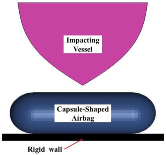
Figure 1.
Finite element model of collision scene.

Table 1.
Model material parameters [10].
In LS-DYNA (R11.1), mass flow rate and temperature are key thermodynamic parameters that characterize the airbag’s inflation and deflation process. Mass flow rate controls gas exchange, affecting internal pressure and energy absorption. During impact, rapid compression and expansion make it a crucial factor in airbag response. Temperature influences stiffness and pressure distribution—compression raises temperature, increasing stiffness, while expansion causes cooling, reducing resistance to deformation. Even in low-speed impacts, these temperature variations affect cushioning performance and must be considered for accurate modeling.
To ensure the practical applicability of the model, certain nodes of the airbag are constrained to a hypothetical rigid wall, simulating the fixed state of the airbag in actual use. The contact within the airbag is defined using the “contact-airbag-single-surface” keyword [20], while the contact between the airbag, wall, and impact ship components is defined using the surface-to-surface contact algorithm. According to general rules, the master and slave surfaces are determined: the ship and airbag select the stiffer ship as the master surface, the airbag and rigid wall select the stiffer rigid wall as the master surface, and between the ship and the rigid wall, the larger and planar rigid wall is chosen as the master surface. During the collision simulation, the humidity of the environment is considered, and the friction coefficient is set to 0.5 to simulate physical phenomena under high humidity conditions, ensuring that the frictional behavior aligns with the contact characteristics in an actual moist environment. This parameter setup brings the simulation closer to real maritime collision scenarios, enhancing the reliability and practical value of the simulation results.
2.2. Validation Based on Model Tests
Figure 2 shows the time-history responses of the impact force between the airbag and the rigid wall, together with the acceleration of the striking ship. The collision-force curve presents a distinct single-peak shape, illustrating that the airbag’s deformation during compression and rebound proceeds in a stable and continuous manner. The acceleration record indicates that the ship’s motion gradually increases to a maximum value and then decreases until it returns to rest after separating from the airbag.
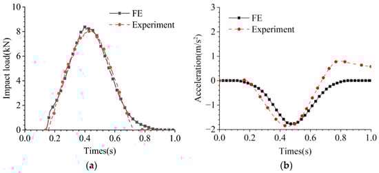
Figure 2.
Collision force and acceleration time history curve, (a) Collision force curve; (b) Acceleration curve.
Both the experimental and numerical results demonstrate a close correlation in the variation patterns of collision force and acceleration. In the physical test, the maximum impact force reached 8.03 kN, while the finite-element simulation predicted 8.37 kN, yielding a 4.1% difference. The corresponding peak accelerations were 1.87 m/s2 and 1.77 m/s2 for the experiment and the simulation, respectively, differing by 5.3%. The minor deviations can be attributed to the asymmetric deformation of the airbag in the experiment, which slightly changes the acting direction of the load, and to the simplified treatment of hydrodynamic effects through the added-mass approach. Despite these differences, the overall agreement in force amplitude, acceleration response, and impact duration confirms the reliability of the finite-element simulation method. The entire contact process—from initial engagement to full separation—lasted approximately 0.7 s in both cases, validating the model’s capability to reproduce the dynamic energy-dissipation behavior observed in the experiments.
3. Airbag Protection Design and Comparative Analysis of Protective Performance
3.1. Structural Design and Layout of Double-Chamber Airbags
Airbags are generally categorized into three structural types: sealed, vented, and combined. Sealed airbags absorb impact energy through internal gas compression and elastic rebound; vented airbags release energy through a vent once the internal pressure exceeds a specified threshold; combined airbags integrate the features of both types, typically employing a double-chamber design. In this study, the cushioning performance of a novel double-chamber airbag is evaluated through numerical simulations, using a finite element model validated in Section 2.2. It should be noted, however, that the absence of direct physical testing for the double-chamber design introduces certain uncertainties, particularly in relation to venting behavior and material deformation.
In this design, the airbag adopts a double-chamber configuration, integrating a vented unit for pressure relief and a sealed unit for load stabilization (Figure 3). The vented chamber, positioned adjacent to the impacted compartment, absorbs collision energy by expelling gas through a one-way vent valve when overpressure occurs, thereby reducing structural damage. The sealed chamber, located closer to the striking ship, is smaller in size and has no vent openings. During impact, it stabilizes the structure and protects the vented chamber from direct contact with the striking bow, preventing excessive deformation or puncture and ensuring effective cushioning.
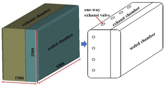
Figure 3.
Structural design of double-chamber airbag.
To maintain equal initial pressure between the two chambers before impact, the SET_SEGMENT command in LS-DYNA (R11.1) was employed to define each chamber separately, combined with a mass flow rate equation for independent inflation. This approach enables a more realistic simulation of the inflation process and improves the accuracy of evaluating the airbag system’s performance.
3.2. Finite Element Model
The principal dimensions of both the striking and impacted ships are summarized in Table 2. To concentrate on the deformation response of the impacted vessel’s side structure and evaluate the airbag’s protective capability, the striking ship is represented as a rigid body. This simplification, commonly adopted in ship–ship collision research, enables accurate computation of collision forces while maintaining high efficiency. Because the damage sustained by the striking ship is not of primary concern in this study, the rigid-body assumption allows a more precise assessment of the airbag’s performance.
Table 2.
Ship main dimension.
For computational efficiency, all internal structural components of the striking vessel were excluded from the model. A partial finite-element representation of the impacted ship was then established, comprising three adjacent watertight compartments. The draft of the impacted vessel was adjusted by modifying its material density. The developed finite-element configurations are illustrated in Figure 4.
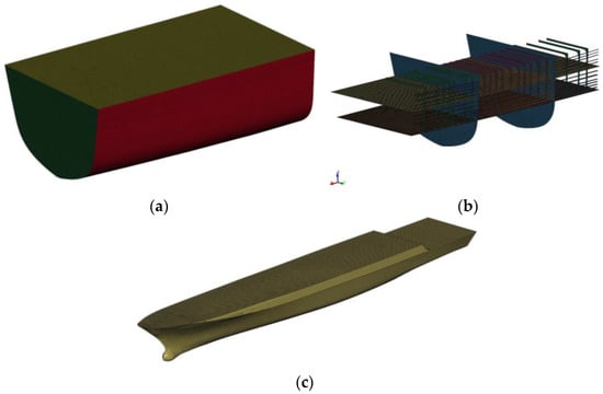
Figure 4.
Finite element model, (a) Impacted compartment; (b) Internal Structure of impacted Compartment; (c) Finite element model of impact ship.
In the simulation framework, the airbag device was pre-mounted on the ship’s side and maintained in a fully inflated state throughout the analysis. Given that the side structure of a vessel is particularly susceptible to collision-induced damage [21,22], the study emphasizes the airbag’s role in improving lateral impact resistance. The protective airbag installed on the compartment is depicted in Figure 5a, measuring 5 m × 2.5 m × 1.5 m. The corresponding layout is shown in Figure 5b. To ensure efficient energy absorption at the prescribed internal pressure, an initial clearance of 0.2 m was introduced between the striking ship and the airbag before impact. Additionally, to avoid penetration during collision, a customized contact definition for the airbag was employed, which executes contact detection more frequently than conventional methods, resulting in a more realistic simulation of its dynamic behavior.
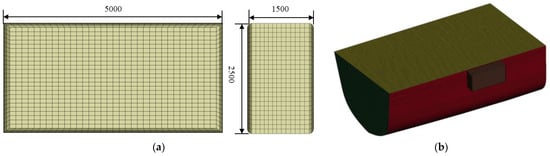
Figure 5.
Dimensions of single-chamber airbag and its side arrangement airbag, (a) Dimensions of single-chamber airbag; (b) Airbag arrangement location.
3.3. Typical Ship Collision Scenarios
The material characteristics of the components involved in the collision scenario are summarized in Table 3. The impacted compartment is constructed from marine-grade steel AH36, which has a failure strain of 0.3 [23]. Figure 6 illustrates the collision configurations both with and without airbag protection. Under standard conditions, the striking vessel travels at 5 knots and collides at an impact angle of 45 degrees. The contact point is positioned slightly above the patrol ship’s draft line, aligning with the center of the protective airbag. The principal parameters of the airbag are provided in Table 4.
Table 3.
Material parameters of components in typical collision scenarios.
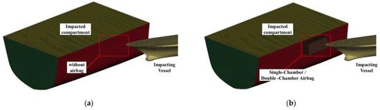
Figure 6.
Comparison of collision conditions: (a) without Airbag Protection; (b) with single- or double-chamber airbag protection.
Table 4.
Airbag configuration parameters.
It should be noted that the initial pressure and vent area were guided by the experimental data of Pan et al. [17] but were adjusted to reflect the geometry of the present double-chamber airbag and finalized through sensitivity analyses to ensure stable and realistic simulation responses. The exhaust threshold was set slightly above the initial pressure according to engineering practice, so that venting occurs only under collision-induced overpressure.
3.4. Analysis of Simulation Results
Figure 7 and Table 5 present the time-history response of the collision force. Without airbag protection, the maximum load reaches 2.92 MN, and the impact duration is only 0.54 s, meaning that most kinetic energy is directly transmitted to the ship’s structure. When the airbag is applied, the peak load decreases to 1.97 MN, and the contact time becomes notably longer. A secondary peak appears at approximately 2.6 s, suggesting a re-contact between the striking vessel and the compartment. This behavior confirms that the airbag significantly mitigates structural stress by absorbing and dispersing the impact energy.
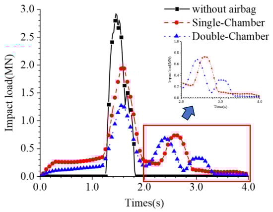
Figure 7.
Collision-force time histories under various impact conditions.
Table 5.
Comparison of maximum impact load and contact duration for different airbag configurations.
For the single-chamber airbag, the maximum impact load is 1.97 MN, with the total interaction period extending to about 2.96 s. The secondary contact observed at 2.6 s indicates a rebound effect, which prolongs the buffering process and enables more efficient energy dissipation, thereby lessening the structural deformation of the hull.
Further comparison reveals that the maximum collision force in the case of the double-chamber airbag is 1.27 MN—approximately 0.7 MN (35.5%) lower than that obtained with the single-chamber configuration. This improvement is attributed to the coordinated function of the sealed and vented chambers: the sealed chamber maintains geometric stability, while the vented one releases internal pressure through gas discharge. Such a mechanism enhances energy absorption and damping performance, effectively reducing the impact load transmitted to the protected compartment.
Table 6 compares the damage and deformation characteristics of the impacted compartment under different protection configurations. The first comparison concerns the cases with a single-chamber airbag and without any protective device. Without airbag protection, the compartment experiences severe plastic deformation, with the maximum strain reaching 0.248, particularly concentrated in the side shell plating and transverse framing. When the single-chamber airbag is applied, the peak strain decreases to 0.167, and the plastic-strain contours reveal a substantially smaller damaged area than that observed in the unprotected case. This indicates that the addition of an airbag effectively absorbs and dissipates collision forces, thereby reducing the stress and deformation of the ship’s structural components.
Table 6.
Comparison of Damage and Deformation between Compartment and Side Shell Structure.
Furthermore, examining the damage cloud diagram of the compartment protected with a double-chamber airbag shows that the maximum strain is 0.147, which is a reduction of 0.02 compared to the single-chamber scenario with a strain of 0.167. Additionally, the plastic deformation cloud diagram reveals that the damage area is more localized in the double-chamber airbag scenario. This further demonstrates the effectiveness of the double-chamber design in absorbing impact energy and limiting damage propagation. Overall, compared to the single-chamber airbag, the double-chamber airbag provides superior protection in reducing structural strain and damage caused by collisions.
In the unprotected condition, the collision energy is primarily absorbed by the ship’s structural components, especially the side shell and transverse frames, which account for 439.0 kJ (50.02%) and 278.2 kJ (31.76%) of the total absorbed energy, respectively. This direct energy transfer leads to significant plastic deformation in key areas. When a single-chamber airbag is installed, it absorbs 474.8 kJ (52.3%) of the impact energy, significantly reducing the load borne by structural components. Consequently, the energy absorbed by the side shell and transverse frames drops to 189.1 kJ and 149.7 kJ, leading to reduced deformation and improved structural resilience.
Figure 8c shows the energy absorption under the double-chamber airbag configuration. The total absorbed energy reaches about 1300 kJ, higher than both the unprotected and single-chamber cases. The vented chamber dissipates energy through controlled gas release, prolonging the collision duration and lowering the peak load, while the sealed chamber stabilizes the structure. Consequently, most of the energy is carried by the airbag system, leaving only minimal residual loads on the side shell and other components. This confirms the superior buffering and protective performance of the double-chamber design in mitigating collision-induced structural damage.
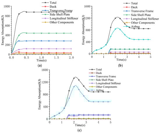
Figure 8.
Energy-absorption histories of structural components under various airbag configurations: (a) without airbag protection; (b) with single-chamber airbag; (c) with double-chamber airbag.
4. Parameter Sensitivity Analysis
To comprehensively assess the crash-resistance capability of the double-chamber airbag in side-impact situations, numerical simulations were performed under representative operating conditions. The impact velocity and angle were varied independently, while other parameters were held constant, to examine their individual effects on the structural response. The selected velocity range of 3–9 kn represents typical low- to moderate-speed encounters for coastal and law-enforcement vessels, consistent with the conditions considered in ship-collision risk modeling studies [24]. Similarly, the impact angles between 30° and 90° cover realistic collision orientations frequently analyzed in experimental investigations of oblique impact behavior [25]. When examining impact velocity, the collision angle was fixed at 45°, whereas in the analysis of impact angle, the vessel speed was maintained at 5 knots.
4.1. Effect of Initial Impact Velocity
To accurately assess the impact of collisions on the ship’s structure under airbag protection, this study adopts the concept of relative velocity and assumes that the impacted ship is stationary. This assumption not only simplifies the complexity of the collision process but also facilitates an in-depth exploration of the side structure’s collision response under different impact velocities from both theoretical and practical perspectives. Through this method, it is possible to more accurately simulate and analyze the dynamic changes during the collision process, providing important references for the safety protection design of patrol vessels.
Considering the various situations ships may encounter during missions, such as high-speed pursuits, interceptions, and emergency evasions, setting a reasonable impact speed is crucial for studying the physical phenomena during collisions and the response of the ship structure. Therefore, this study selects four different impact speeds—3 kn, 5 kn, 7 kn, and 9 kn—to simulate scenarios with varying collision intensities, thereby comprehensively evaluating the structural safety after equipping with double-chamber airbag protection. Under the stationary-ship assumption, the striking ship’s velocity denotes the relative speed between the two vessels, ensuring physical consistency in the simulation.
From Table 7, it can be seen that as the speed of the striking ship increases, the strain value of the impacted compartment continues to rise, leading to increased damage and deformation. Specifically, when the impact speeds reach 7 knots and 9 knots, the strain values of the impacted compartment are 0.203 and 0.296, respectively. As the impact velocity increases, the collision force generated during the collision also increases, resulting in greater stress and strain on the hull, which leads to more severe structural damage, including localized denting of the impacted compartment. When the impact speed is 3 knots, the plastic strain of the compartment is 0, indicating that no plastic deformation occurred in the impacted compartment. This suggests that at lower speeds, the airbag can effectively absorb the collision force from the striking ship, preventing direct contact with the impacted compartment, thereby demonstrating the airbag’s effectiveness in mitigating collision forces.
Table 7.
Damage deformation cloud diagrams of the compartment under double-chamber airbag protection at different impact velocities.
From Figure 9, it can be observed that the presence of the airbag protection device significantly prolongs the collision duration. This is visually reflected in the extended nature of the load curves at different velocities in the figure. In terms of the time distribution of collision force, the presence of the airbag results in a more gradual force distribution over time, which helps reduce the impact pressure on the ship structure in a short period, thereby mitigating structural damage. At an impact speed of 3 knots, the airbag effectively absorbs the energy from the striking ship, preventing direct contact between the striking ship and the impacted compartment, ensuring that the collision force on the side shell remains relatively low, with a peak value of only 0.092 MN. This demonstrates the airbag’s effective protective and energy-absorbing capabilities under low-speed collisions. At higher collision speeds, due to the same initial position of the striking ship, while the airbag still provides a certain level of protection, the peak collision force and its occurrence time advance with increasing impact speed. At impact speeds of 7 knots and 9 knots, even with the cushioning effect of the airbag, considerable energy is still transferred to the impacted compartment, with peak collision forces reaching 2.42 MN and 1.55 MN, respectively. This indicates that at higher speeds, the collisions among the striking ship, the impacted ship, and the airbag are more intense, and the duration of impact is relatively longer.
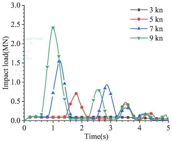
Figure 9.
Variation in collision force with time for different impact speeds.
4.2. Effect of Initial Impact Angles
In maritime collision accidents, the impact angle is a key factor affecting collision outcomes, including the distribution of collision forces and the integrity of the structure. Collisions between ships typically occur at various angles, making it crucial to analyze the effects of different impact angles in the design of collision protection systems. This not only helps evaluate the performance of double-chamber airbags but also provides guidance for structural design and safety standards.
Right-angle collisions (90 degrees) are considered the most severe, as nearly all kinetic energy is transferred to the impacted ship, causing maximum structural damage. Non-perpendicular collisions, however, are common when ships attempt to avoid direct contact or due to operational errors and poor visibility, leading to oblique impacts. Despite the presence of airbag protection, different impact angles can still lead to various forms of structural damage and safety risks. Therefore, this section analyzes angles of 30 degrees, 45 degrees, 60 degrees, 75 degrees, and 90 degrees, aiming to provide more comprehensive protective measures for government ships equipped with double-chamber airbags, ensuring their safety and reliability during missions. Figure 10 presents a simplified schematic of the collision angle.
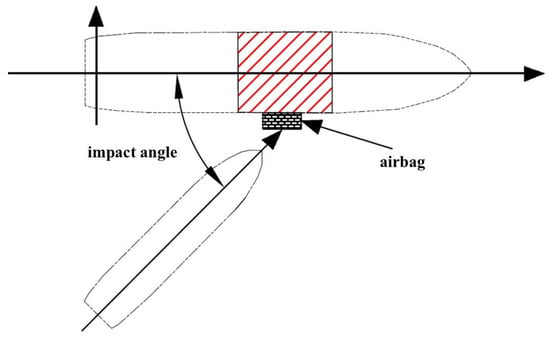
Figure 10.
Illustration of impact angles.
Table 8 shows that with increasing impact angle, the strain level of the impacted compartment rises continuously, leading to more significant structural deformation. When the impact angle is 30°, the compartment exhibits nearly no plastic strain, suggesting that at small angles the airbag efficiently dissipates impact energy and prevents direct contact between the two vessels. This indicates its strong buffering capacity in reducing collision-induced loads. As the angle increases to 75° and 90°, the equivalent plastic strain of the side shell grows markedly, reaching 0.204 and 0.297, respectively. The increase occurs because, at larger angles, the contact area expands and the collision force is spread over a wider region of the side hull, producing more severe overall damage.
Table 8.
Damage deformation cloud diagrams of the compartment under double-chamber airbag protection at different impact angles.
The impact load on the compartment gradually increases as the collision angle becomes larger (see Figure 11). At smaller impact angles, such as 30°, the force curve shows a lower and smoother peak, with a peak value of 0.092 MN occurring later in the impact process. This indicates that the airbag performs exceptionally well under such conditions, efficiently absorbing the impact energy and significantly reducing the force exerted on the side structure. This demonstrates the airbag’s effectiveness in protecting the ship during small-angle impacts, showcasing its strong protective capability.
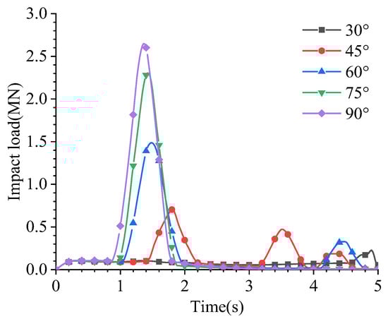
Figure 11.
Collision-force time histories at varying impact angles.
At larger impact angles of 75° and 90°, the peak collision force increases significantly, reaching 2.30 MN and 2.64 MN, respectively. This suggests that at larger impact angles, the collision force transmission path is more direct and shorter, causing a substantial amount of impact energy to be transferred directly to the impacted ship without much dispersion. In the angle range of 30° to 60°, the collision force curves are relatively similar, indicating that the airbag can still function effectively within this range. However, at impact angles of 75° and 90°, while the airbag still provides some cushioning effect, its ability to absorb the collision force diminishes, resulting in more energy being transferred to the impacted compartment.
5. Conclusions
This study proposes a double-chamber airbag system to improve ship collision protection, building upon the experimental work of Pan J et al. [17] and extending it through numerical simulations. The effectiveness of the system was evaluated by comparing collision responses in three scenarios: no airbag, single-chamber airbag, and double-chamber airbag. The key findings are as follows:
- (1)
- Compared with both the single-chamber and unprotected cases, the double-chamber fender exhibited markedly superior performance—manifested in lower structural strain levels, prolonged impact duration, and more efficient redistribution of collision energy.
- (2)
- Energy-distribution analysis indicated that, without protection, the majority of kinetic energy was taken up by the side shell and internal framing, producing considerable plastic deformation. When equipped with the double-chamber device, however, more than half of the total energy was dissipated within the airbag system, substantially reducing the load transmitted to the ship’s primary structure.
- (3)
- Across different velocities and collision angles, the proposed system consistently provided stable cushioning behavior. Notably, at high-energy or oblique impacts, the double-chamber configuration postponed the occurrence of peak forces and limited structural damage to smaller localized zones.
The results suggest that the double-chamber design may offer improved energy absorption and damage mitigation compared to single-chamber alternatives. Nevertheless, this study has some limitations, as the design was evaluated solely through numerical simulations with a simplified hydrodynamic representation and idealized material assumptions. These factors may affect the quantitative accuracy of the results. Future work will therefore focus on scaled or full-scale experiments to validate the reliability and practical performance of the double-chamber system, as well as on incorporating more refined hydrodynamic models and extending the approach to realistic ship–ship collision scenarios. Moreover, integrating intelligent perception and risk assessment techniques could further enhance the applicability of the proposed fender system [26,27], which may offer valuable support for adaptive control and real-time protection in future applications.
Author Contributions
Conceptualization, Z.W. and K.L.; methodology, Z.W. and Z.G.; formal analysis, Z.W.; data curation, Q.M.; visualization, Q.M.; writing—original draft, Z.W.; writing—review and editing, W.Q.; supervision, K.L. and Z.G. All authors have read and agreed to the published version of the manuscript.
Funding
This research was supported by the National Natural Science Foundation of China (Grant Nos. 52571350, 52271279, and 52171311).
Data Availability Statement
The data supporting the findings of this study are available from the corresponding author upon reasonable request.
Conflicts of Interest
The authors declare no conflicts of interest.
References
- Chen, J.; Fang, H.; Zhuang, Y.; Shen, Z.; He, W. Crushing behavior of multi-layer lattice-web reinforced double-braced composite cylinders under lateral compression and impact loading. Thin-Walled Struct. 2023, 193, 111289. [Google Scholar] [CrossRef]
- Cheng, Y.; Liu, K.; Li, Y.; Wang, Z.; Wang, J. Experimental and numerical simulation of dynamic response of U-type corrugated sandwich panels under low-velocity impact. Ocean Eng. 2022, 245, 110492. [Google Scholar] [CrossRef]
- Niklas, K.; Bera, A.; Garbatov, Y. Impact of steel grade on a ship colliding with an offshore wind turbine monopile supporting structure. Ocean Eng. 2023, 287, 115899. [Google Scholar] [CrossRef]
- Zhao, S.; Fang, H.; Wang, R.; Cao, P. Ship collision performance of a fiber-reinforced composite material winding tube filled with ceramic pellets. Eng. Struct. 2025, 324, 119335. [Google Scholar] [CrossRef]
- Fan, W.; Guo, W.; Sun, Y.; Chen, B.; Shao, X. Experimental and numerical investigations of a novel steel-UHPFRC composite fender for bridge protection in vessel collisions. Ocean Eng. 2018, 165, 1–21. [Google Scholar] [CrossRef]
- Wang, J.; Song, Y.; Wang, W.; Tu, L. Evaluation of composite crashworthy device for pier protection against barge impact. Ocean Eng. 2018, 169, 144–158. [Google Scholar] [CrossRef]
- Zhou, L.; Li, H.; Wei, J.; Pu, X.; Mahunon, A.D.; Jiang, L. Design and simulation analysis of a new type of assembled UHPC collision avoidance. Appl. Sci. 2020, 10, 4555. [Google Scholar] [CrossRef]
- Yan, H.; Fang, H.; Zhu, L.; Jia, E.; Dai, Z.; Zhang, X. Evaluation of a novel steel box-soft body combination for bridge protection against ship collision. Rev. Adv. Mater. Sci. 2023, 62, 20220295. [Google Scholar] [CrossRef]
- Wang, F.; Chang, H.-J.; Ma, B.-H.; Wang, Y.-G.; Yang, L.-M.; Liu, J.; Dong, X.-L. Flexible guided anti-collision device for bridge pier protection against ship collision: Numerical simulation and ship collision field test. Ocean Eng. 2023, 271, 113696. [Google Scholar] [CrossRef]
- Cho, H.R.; Kim, H.J.; Park, S.M.; Park, D.K.; Yun, S.H.; Paik, J.K. Effect of solid rubber fenders on the structural damage due to collisions between a ship-shaped offshore installation and an offshore supply vessel. Ships Offshore Struct. 2023, 18, 1037–1059. [Google Scholar] [CrossRef]
- Elaidy, A.; Rayner, R.; Kalyvas, C. Innovative Design of External Airbag System for Improved Automotive Safety. IEEE Open J. Veh. Technol. 2024, 5, 967–978. [Google Scholar] [CrossRef]
- Nayak, R.; Padhye, R.; Sinnappoo, K.; Arnold, L.; Behera, B.K. Airbags. Text. Prog. 2013, 45, 209–301. [Google Scholar] [CrossRef]
- Shaout, A.; Mallon, C.A. Automotive airbag technology: Past, present and future. Int. J. Comput. Appl. Technol. 2000, 13, 159–171. [Google Scholar] [CrossRef]
- Franco, B.; Alves Ribeiro, J.M.; Sánchez-Arce, I.d.J. Development of an Airbag Geometry Specific for Autonomous Vehicles. Eng 2023, 4, 2553–2570. [Google Scholar] [CrossRef]
- Zhou, X.; Zhou, S.; Li, D.; Cui, D.; Dong, C. Research on design and cushioning performance of combined lunar landing airbag. Acta Astronaut. 2022, 191, 55–78. [Google Scholar] [CrossRef]
- Xu, Y.; Yang, Y.; Huang, H.; Chen, G.; Li, G.; Chen, H. Multi-Objective Optimization Design of an Origami-Inspired Combined Cushion Airbag. Aerospace 2024, 11, 169. [Google Scholar] [CrossRef]
- Pan, J.; Peng, H.; Gan, J.; Zhang, W.; Li, X. Study on Crashworthiness Performance of an Airbag Anti-Collision Device for Vessel-Bridge Collision. In Proceedings of the International Conference on Offshore Mechanics and Arctic Engineering, Melbourne, Australia, 11–16 June 2023; p. V002T002A004. [Google Scholar] [CrossRef]
- Park, S.M.; Kim, H.J.; Cho, H.R.; Kong, K.H.; Park, D.K.; Paik, J.K. Effect of pneumatic rubber fenders on the prevention of structural damage during collisions between a ship-shaped offshore installation and a shuttle tanker working side-by-side. Ships Offshore Struct. 2023, 18, 596–608. [Google Scholar] [CrossRef]
- Jun, F.; Jin, P.; Jiangqiang, G.; Xiaobin, L.; Mingcai, X. Collision Performance Analysis of Airbag Anti-Ship Collision Device. In Proceedings of the ISOPE International Ocean and Polar Engineering Conference, Ottawa, ON, Canada, 18–23 June 2023; p. ISOPE–I-23-477. [Google Scholar]
- Zhou, H.; Zhong, Z.; Hu, M. Design and occupant-protection performance analysis of a new tubular driver airbag. Engineering 2018, 4, 291–297. [Google Scholar] [CrossRef]
- Hogström, P. RoPax Ship Collision—A Methodology for Survivability Analysis. Ph.D. Thesis, Chalmers Tekniska Hogskola, Goteborg, Sweden, 2012. [Google Scholar]
- Qiu, W.; Liu, K.; Liu, H.; Zong, S.; Wang, J.; Gao, Z. Crashworthiness Optimization Method of Ship Structure under Multi-Working Conditions. J. Mar. Sci. Eng. 2023, 11, 1335. [Google Scholar] [CrossRef]
- Liu, H.; Liu, K.; Wang, X.; Gao, Z.; Wang, J. On the Resistance of Cruciform Structures during Ship Collision and Grounding. J. Mar. Sci. Eng. 2023, 11, 459. [Google Scholar] [CrossRef]
- Lee, H.J.; Namgung, H. A CDC–ANFIS-Based Model for Assessing Ship Collision Risk in Autonomous Navigation. J. Mar. Sci. Eng. 2025, 13, 1492. [Google Scholar] [CrossRef]
- Xia, J.; Zhang, Q.; Wang, J.; He, Z.; Zhou, Q.; Zhou, D.; Lu, X. Experimental study of the effect of various collision angles and critical conditions on marine engine’s twin-spray collision process. Int. J. Engine Res. 2023, 24, 999–1015. [Google Scholar] [CrossRef]
- Chen, X.; Ma, F.; Wu, Y.; Han, B.; Luo, L.; Biancardo, S.A. MFMDepth: MetaFormer-based monocular metric depth estimation for distance measurement in ports. Comput. Ind. Eng. 2025, 207, 111325. [Google Scholar] [CrossRef]
- Liu, X.; Deng, S.; Liu, T.; Liu, T.; Wang, S. A manoeuvre indicator and ensemble learning-based risky driver recognition approach for highway merging areas. Transp. Saf. Environ. 2024, 6, tdae015. [Google Scholar] [CrossRef]


Disclaimer/Publisher’s Note: The statements, opinions and data contained in all publications are solely those of the individual author(s) and contributor(s) and not of MDPI and/or the editor(s). MDPI and/or the editor(s) disclaim responsibility for any injury to people or property resulting from any ideas, methods, instructions or products referred to in the content. |
© 2025 by the authors. Licensee MDPI, Basel, Switzerland. This article is an open access article distributed under the terms and conditions of the Creative Commons Attribution (CC BY) license (https://creativecommons.org/licenses/by/4.0/).