Article

Hybrid Regularized Variational Minimization Method to Promote Visual Perception for Intelligent Surface Vehicles Under Hazy Weather Condition

1
School of Mechanical Engineering, Northwestern Polytechnical University, Xi’an 710072, China
2
China E-Tech (Ningbo) Maritime Electronics Research Institute Co., Ltd., Ningbo 315040, China
3
College of Information Science & Electronic Engineering, Zhejiang University, Hangzhou 310058, China
*
Author to whom correspondence should be addressed.
J. Mar. Sci. Eng. 2025, 13(10), 1991; https://doi.org/10.3390/jmse13101991
Submission received: 19 July 2025 / Revised: 7 September 2025 / Accepted: 16 September 2025 / Published: 17 October 2025
(This article belongs to the Special Issue Emerging Computational Methods in Intelligent Marine Vehicles)

Abstract

Intelligent surface vehicles, including unmanned surface vehicles (USVs) and autonomous surface vehicles (ASVs), have gained significant attention from both academic and industrial communities. However, shipboard maritime images captured under hazy weather conditions inevitably suffer from a blurred, distorted appearance. Low-quality maritime images can lead to negative effects on high-level computer vision tasks, such as object detection, recognition and tracking, etc. To avoid the negative influence of low-quality maritime images, it is necessary to develop a visual perception enhancement method for intelligent surface vehicles. To generate satisfactory haze-free maritime images, we propose development of a novel transmission map estimation and refinement framework. In this work, the coarse transmission map is obtained by the weighted fusion of transmission maps generated by dark channel prior (DCP)- and luminance-based estimation methods. To refine the transmission map, we take the segmented smooth feature of the transmission map into account. A joint variational framework with total generalized variation (TGV) and relative total variation (RTV) regularizers is accordingly proposed. The joint variational framework is effectively solved by an alternating-direction numerical algorithm, which decomposes the original nonconvex nonsmooth optimization problem into several subproblems. Each subproblem could be efficiently and easily handled using the existing optimization algorithm. Finally, comprehensive experiments are conducted on synthetic and realistic maritime images. The imaging results have illustrated that our method can outperform or achieve comparable results with other competing dehazing methods. The promoted visual perception is beneficial to improve navigation safety for intelligent surface vehicles under hazy weather conditions.

1. Introduction

Intelligent surface vehicles, e.g., unmanned surface vehicles (USVs) and autonomous surface vehicles (ASVs), etc., have received scholarly attention for promoting the construction and development of maritime intelligent transportation systems. Many onboard sensors, e.g., visible-light/thermal-infrared cameras, automatic identification systems (AIS), radar, etc., have been widely exploited to improve the capacity of situational awareness for surface vehicles under complex navigation environments. Owing to the higher performance–price ratio, visible-light cameras attract more attention and play an important role in promoting safe navigation. However, visible-light maritime images easily suffer from a blurred, distorted appearance under hazy weather conditions. The visually degraded images will lead to negative influences on subsequent tasks for surface vehicles, such as object detection, recognition, tracking, visual navigation, etc. [1,2]. Therefore, it is necessary to effectively restore high-quality images from the haze-degraded images.
Currently, significant progress has been made in image dehazing techniques, which can be broadly categorized into three types: contrast enhancement methods, physics-based imaging methods, and deep learning-based methods. Although these approaches can effectively improve image quality in general scenarios, they still exhibit certain limitations. Contrast enhancement methods tend to lose valuable information; physics-based methods have shortcomings in estimating the transmission map and modeling image degradation under complex maritime environments; deep learning-based methods, while achieving excellent performance, rely heavily on high-quality training data and still show estimation errors in the transmission map for sky and water regions.
Therefore, there is an urgent need for an image dehazing method that can adapt to complex maritime scenarios, reduce dependence on high-quality training data, and maintain accurate transmission estimation in sky and water regions, thereby enhancing the visual perception and navigational safety of surface vessels under hazy conditions. This study proposes a corresponding solution to address these issues and validates through experiments its effectiveness in improving image quality and enhancing maritime object detection performance.

1.1. Related Works

1.1.1. Contrast Enhancement Methods

Images captured in haze environments have low contrast. Therefore, many methods have been proposed to eliminate haze through contrast stretching. Early attempts, e.g., histogram equalization (HE) and its extended versions [3,4] transformed the histogram into a uniform distribution for enhancing the contrast of hazy images. Zhou et al. [5] proposed a single image dehazing method based on Retinex theory [6], which decomposed one image into reflection and illumination for enhancing separately. Ancuti et al. [7] introduced a multi-scale fusion-based strategy to improve the visibility of hazy images, designing weight maps to effectively fuse image information. However, since the inherent degradation characteristic of hazy images is ignored, valuable information is easily lost in contrast enhancement methods. Therefore, it is challenging to eliminate the degrading effect of hazy images by these methods.

1.1.2. Physical-Based Methods

Through the analysis of haze generation, numerous physical-based methods have been proposed. Specifically, these methods regard the image dehazing task as an inverse problem, where the parameters of image degradation models are estimated from hazy images. For instance, Fattal [8] proposed a transmission estimation method based on surface shading to restore clear images. Berman et al. [9] found that a haze-free image can be well approximated by a few hundred distinct colors to form clusters in RGB space, i.e., non-local prior. In particular, each color cluster is represented by a haze line. A method for restoring a haze-free version by identifying those haze-lines was thus constructed. Based on the fact that pixels of small patches in natural images typically exhibit a 1D distribution in RGB color space, Fattal introduced color-lines prior [10]. In addition, Fattal proposed an image dehazing method base on Markov random field, which is dedicated to estimating transmission maps on noisy and scattered scenes. He et al. [11] proposed the dark channel prior (DCP) according to statistics of natural haze-free images. Based on DCP, He proposed a novel method to estimate transmission and restore the haze-free image. However, DCP-based methods [11,12] easily fail in sky and water regions due to the deviation of transmission estimation. To avoid this problem, Zhu et al. [13] proposed a fusion of luminance and dark channel prior (F-LDCP) strategy to estimate the transmission of sky and water regions accurately. According to our research, physical-based methods can excavate the potential details in the degraded image as much as possible. However, limitations of this kind of method still exist in maritime scenes due to the complexity and ill-posedness of the dehazing problem.

1.1.3. Deep Learning-Based Methods

With the development of convolutional neural networks (CNNs), various deep learning-based methods have been proposed and have made significant advances in dehazing issues. According to our research, deep learning-based image dehazing methods can be divided into parameter estimation and end-to-end methods. DehazeNet [14] was a typical dehazing network for parameter estimation, which obtains dehazed versions by estimating transmission. Subsequently, Ren et al. [15] proposed a multi-scale convolutional neural network (MSCNN) for transmission estimation. However, it is difficult to collect transmission and atmospheric light of images. To solve the problem caused by the dataset, an unsupervised dehazing strategy [16] was designed. Instead of using the training method utilising paired datasets, this method generates transmission by minimizing the energy function of the dark channel prior. Chen et al. [17] defined a new feature called patch map and proposed the patch-map-based hybrid learning DehazeNet (PMHLD). More recently, a deep network-enabled three-stage dehazing network was developed to enhance the imaging quality for visual Internet of Things (IoT)-based intelligent transportation systems [18]. A parameter-adaptive fusion method, related to the new color channel and preserved brightness, was proposed to perform single image dehazing in intelligent transportation systems [19]. In addition, an unsupervised dehazing method, taking into consideration the patch-line and fuzzy clustering-line priors, was presented to accurately estimate the atmospheric scattering parameters and haze-free images [18]. The improved image quality helps enhance ship detection [20] accuracy under hazy weather conditions and contributes to traffic safety. Although the deep learning methods have demonstrated superior performance for image dehazing tasks, strong dependence on high-quality training images is still a problem that cannot be ignored in maritime applications.

1.2. Motivation and Contributions

Although image dehazing has made remarkable achievements, few studies have been proposed for intelligent surface vehicles and maritime scenes. Undoubtedly, maritime images contain more homogeneous regions than plain images, e.g., sky and water. However, many methods fail to suppress the haze in these regions. For instance, dark channel prior (DCP) [11] easily cause a block effect in backgrounds [21]. It is thus necessary to develop more advanced dehazing methods to improve the imaging quality under hazy weather conditions.
Motivated by the great performance of regularized methods in maritime image enhancement tasks [22,23], we proposed a joint variational regularized framework for refining the transmission map. In this paper, maritime image dehazing is performed in two steps, as illustrated in Figure 1. For solving the worse performance of DCP in sky regions, the transmission maps estimated by different methods are integrated as the coarse transmission map. Subsequently, according to the segmented smooth feature of the transmission map, TGV (Total Generalized Variation) [24] and RTV (Relative Total Variation) [25] regularizers are adopted to this joint variational framework to constrain the transmission map, as detailed in Algorithm 2. TGV is a regularization method that denoises images while preserving edges by balancing first- and higher-order gradients, whereas RTV distinguishes structures from textures based on the relative variation of local gradients, allowing textures to be smoothed while retaining important structures. It has the capacity to restore hazy images and improve detection results.
Algorithm 1 Hybrid Regularized Variational Dehazing
1:
Input: Hazy image I , Optimal parameters λ 1 5 , β 1 , 2 .
2:
Initialize:  i = 0 .
3:
Estimate A , t d according to DCP theory [11], Equation (6).
4:
Estimate t l according to Luminance-based model Equation (7).
5:
Fusion t ¯ by ( t d , t l ) according to Equation (9).
6:
Build refined model Equation (15), decompose into sub-problems.
7:
Define  X 0 , Y 0 , J ¯ 0 , t 0 .
8:
While a stopping criterion is not satisfied do
9:
     Update X i + 1 form Equation (19) for fixed t i ,
10:
   Update Y i + 1 using primal-dual algorithm for fixed J ¯ i ,
11:
   Update J ¯ i + 1 form Equation (22) for fixed t i and Y i + 1 ,
12:
   Update t i + 1 form Algorithm 2 for fixed X i + 1 , J i + 1 , t i , and t ¯ ,
13:
    i i + 1 ,
14:
Restore J according to Equation (3).
15:
Output: Haze-free image J .
In conclusion, the main contributions of this work are summarized as follows
  • Hybrid Variational Method. A hybrid variational model, which combines with TGV and RTV regularizers, is proposed to refine the transmission map. The hybrid regularizer effectively solves the problems of over-smoothness and artifact interference.
  • Numerical Optimization Algorithm. The original transmission-refined model is a nonconvex nonsmooth optimization problem, which is decomposed into simpler subproblems based on the alternating direction method and easily handled by existing numerical methods.
  • Competitive Dehazing Performance. Experiments conducted on synthetic and realistic maritime images proved that the proposed approach could robustly and effectively restore the visibility of hazy images in maritime scenes.
The remainder of this paper is organized into several sections. Section 2 analyzes the image degradation process. Section 3 briefly introduces the fusion process of coarse transmission maps. In Section 4, we propose a hybrid regularized variational dehazing model and the corresponding numerical optimization algorithm. The experimental results on both synthetic and realistic maritime images are presented in Section 5. Finally, we summarize our contributions to this paper in Section 6.

2. Problem Formulation

According to the atmospheric scattering theory firstly introduced by McCartney [26], images captured by imaging sensors are mainly composed of two components, i.e., (1) incident light reflected from the object, which is attenuated by the influence of the scattering medium, e.g., particles, water vapor, etc., and (2) atmospheric light reflected from the scattering medium. The hazy image can thus be formulated as follows
I ( x ) = J ( x ) t ( x ) + A ( 1 t ( x ) ) ,
where x is the pixel coordinate, I is the observed hazy image, J is the haze-free image needed to be reconstructed, A is the global atmospheric light, and t is the transmission map related to the depth map, i.e.,
t ( x ) = e β d ( x ) ,
where β is the scattering coefficient related to wavelength, and d is the distance between the target and imaging sensor.
The purpose of image dehazing is to restore the latent haze-free image J from the observed hazy image I . According to Equation (1), the restored image J can be estimated as follows
J ( x ) = I ( x ) A max ( t ( x ) , t ϵ ) + A .
with t ϵ > 0 being a small constant to avoid instability.
Image dehazing is a typical ill-posed inverse problem since both transmission map t and atmospheric light A are commonly unknown. The dehazing performance strongly depends upon the accurate estimation of the transmission map. To achieve high-quality dehazing, it is thus important to accurately estimate the transmission map using satisfactory physical priors related to latent haze-free images. In this work, we will propose a coarse-to-fine strategy to accurately estimate the transmission map, assisting in yielding high-quality dehazing results.

3. Estimation of Coarse Transmission Map

This section will introduce both DCP and luminance priors to estimate the coarse transmission map.

3.1. DCP-Based Transmission Map

Through the statistical analysis of outdoor haze-off images, He et al. [11] concluded that some pixels with extremely low intensities exist in at least one color channel for most of the local image areas except large sky regions. This observation forms a famous prior (i.e., DCP), which is described as follows
J dark ( x ) = min y Ω ( x ) min c { r , g , b } J c ( y ) 0 ,
where J dark denotes the dark channel, Ω ( x ) is a local patch centered at x . The concept of DCP is essentially beneficial for estimating the transmission map t in Equation (3). In particular, it is necessary to first calculate the atmospheric light A . Among the pixels, related to the top 0.1 % of brightest pixels in the dark channel, the one with the maximum intensity in I could be selected as the global atmospheric light A . After the estimation of A , we can calculate the dark channel of I and J in Equation (1), and then put the minimum operators on both sides, i.e.,
min y Ω ( x ) min c I c ( y ) A c = t ( x ) min y Ω ( x ) min c J c ( y ) A c + 1 t ( x ) .
Based on the assumption of DCP in Equation (4), the DCP-based transmission map t d can be estimated from Equation (5), i.e.,
t d ( x ) 1 μ min y Ω ( x ) min c I c ( y ) A c ,
where μ is a constant parameter and empirically set to 0.95 . It could guarantee natural-looking results in maritime practice.
For most hazy images without large sky regions, DCP could achieve satisfactory dehazing in terms of both quantitative and qualitative evaluations. The maritime images, captured for vehicle surveillance, often contain large sky and water regions. Within these regions, the assumption of DCP is inevitably invalid because the intensity value of the dark channel is much greater than zero. According to Equations (5) and (6), it is easy to derive an underestimation of the dark channel, leading to the inaccurate t d , obviously smaller than the actual version. As illustrated in Figure 2, the DCP-based transmission map t d is almost equal to zero in the sky and water regions. It can make the dehazing suffer from serious overly dark appearances and halo artifacts. It is thus necessary to accurately estimate the transmission map in large sky and water regions, where DCP commonly fails [27].

3.2. Luminance-Based Transmission Map

Inspired by previous studies [13,27], the luminance-based model can be used to estimate the transmission map in the sky and water regions where DCP fails. The luminance-based transmission map model is essentially based on the luminance channel of a CIE color space. The corresponding transmission map is estimated as follows
t l ( x ) = e β L ^ ( x ) ,
where β is the scattering coefficient, L ^ is the revised value of luminance channel. The scattering coefficient is affected by many factors such as light wavelength, aerosol type, polarization state, and weather conditions. For the sake of convenience, only the wavelengths that play a more important role in light scattering are considered in our method. In this work, the scattering coefficient β of the red, green, and blue channels in RGB images are set to 0.3324, 0.3433, and 0.3502, respectively. Note that the transmission map correlates with the depth map. To estimate the transmission more naturally, it is necessary to obtain the depth map as accurately as possible. Therefore, the luminance is stretched as follows
L ^ ( x ) = τ L * L ( x ) ,
where L is the luminance of the input image, L * is the 95 % percentile value of the luminance channel, τ is a parameter that describes the accurate depth range, which controls the estimation of the transmission map by DCP, and luminance assumptions have a similar distribution.

3.3. Weighted Transmission Map

The coarse transmission map t ¯ ( x ) is obtained by fusing transmission maps (i.e., t d and t l ) with the weight ω at every pixel location x , i.e.,
t ¯ ( x ) = ω ( x ) t d ( x ) + ( 1 ω ( x ) ) t l ( x ) ,
where weight ω ( x ) [ 0 , 1 ] . It is able to take full advantages of t d and t l . In particular, DCP only performs well in transmission map estimation in non-sky and non-water regions, whereas the luminance-based transmission map seems more natural-looking in these regions. The DCP model usually shows satisfactory performance, except for large sky and water regions. The luminance-based model is capable of solving this problem. Therefore, when the pixel x belongs to sky regions, ω ( x ) should be close to 0 and t ¯ ( x ) t l ( x ) ; conversely, ω ( x ) close to 1 and t ¯ ( x ) t d ( x ) when the pixel x belongs to foreground regions. The mathematical model is expressed as follows
ω ( x ) = 1 1 + e θ 1 t d ( x ) + θ 2 ,
where θ 1 , θ 2 are parameters that control the weight distribution. The details definition of θ 1 , θ 2 are given by
θ 1 = 20 max ( t d ( x ) ) min ( t d ( x ) ) ,
and
θ 2 = 10 + θ 1 min ( t d ( x ) ) .
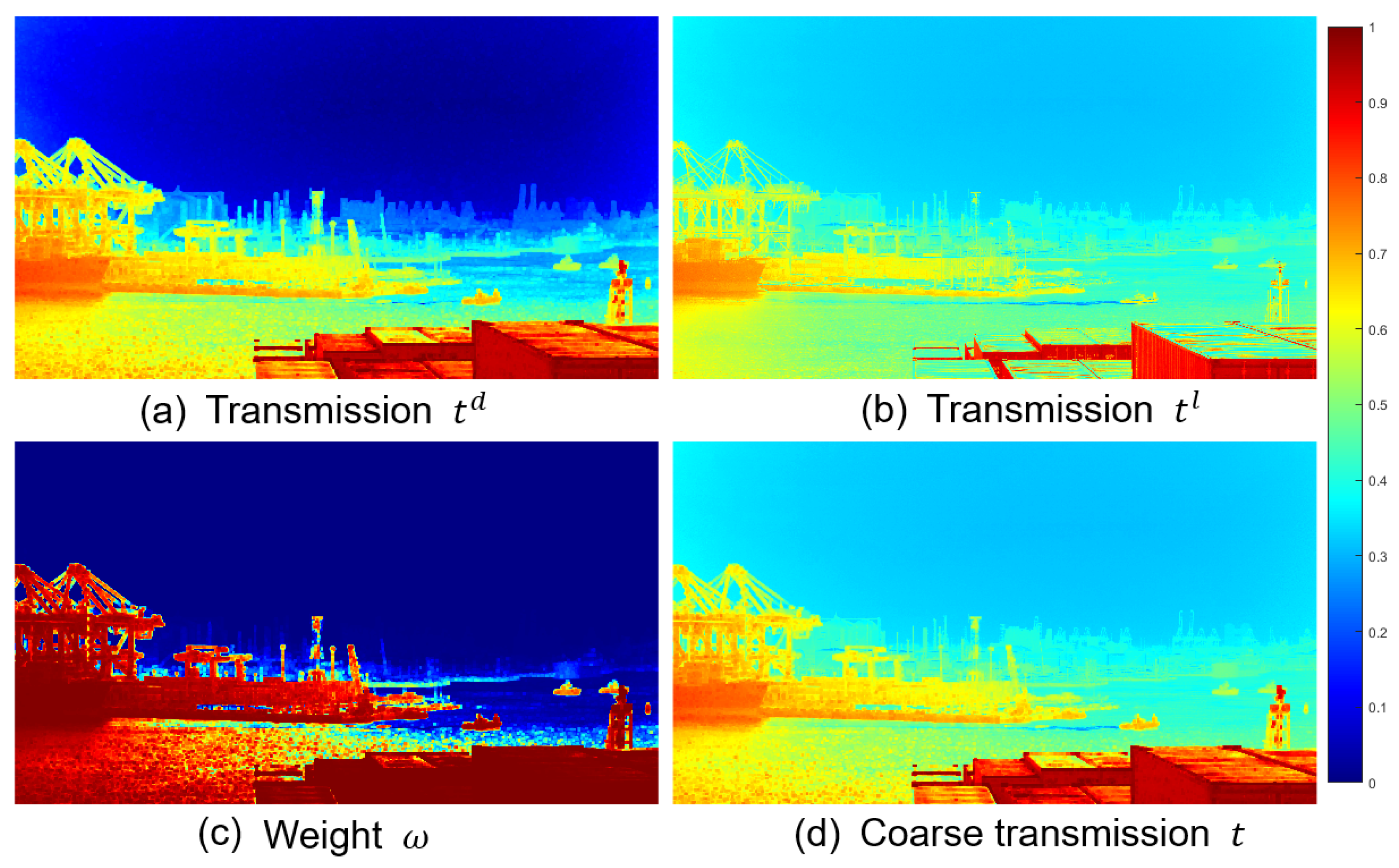
The illustration of the weighted transmission map is displayed in Figure 3. It can be found that our weighted transmission map seems more reasonable due to the t d and t l . However, it contains some undesirable blocky effects because the transmission map is not always uniform in a local patch. We will propose a hybrid variational model to refine the coarse transmission map to improve the visual image quality.

4. Estimation of Refined Transmission Map

In this section, a hybrid variational model and its effective numerical method are proposed to further refine the coarse transmission map t ¯ in Equation (9).

4.1. Hybrid Variational Model

To make transmission map refinement easier, we propose to exploit a more compact imaging model instead of Equation (1). In particular, we first introduce I ¯ = A I and J ¯ = A J , and then rewrite Equation (1) as follows
I ¯ ( x ) = J ¯ ( x ) t ( x ) .
To guarantee a stable solution, the initial value of J ¯ 0 for our numerical method is pre-selected as follows
J ¯ 0 ( x ) = A I ( x ) max t ( x ) , t ϵ ,
where t ϵ is a small constant, avoiding the numerical instability. To maintain the geometrical structures in restored images, it is necessary to accurately refine the transmission map. Therefore, the proper constraints on transmission map refinement should be considered. For the sake of simplicity, we first define I = I c , I ¯ = I ¯ c , J ¯ = J ¯ c , and t ¯ = t ¯ c for c { r , g , b } . The hybrid variational model for estimation of the refined transmission map t is then given by
min J ¯ , t λ 1 2 I ¯ J ¯ t 2 2 + λ 2 2 t t ¯ 2 2 + λ 3 t I 1 + λ 4 TGV ( J ¯ ) + λ 5 RTV ( t ) ,
where λ 1 i 5 is a positive regularization parameter.
It is well known that TGV tends to encourage piece-wise smooth solutions, beneficial for yielding a more natural-looking restoration during image dehazing. In this work, we directly introduce the second-order TGV to regularize the latent sharp image J ¯ in Equation (15), i.e.,
TGV ( J ¯ ) = min L α 1 J ¯ L 1 + α 2 E ( L ) 1 ,
with α 1 and α 2 being positive parameters, and E denoting the symmetrized derivative operator. It is able to suppress the unwanted blocking artifacts inevitably yielded by traditional TV and its extensions. In theory, the transmission map should contain a piece-wise constant appearance within objects and obvious edges at depth discontinuities. To model these properties, the relative total variation (RTV) is exploited to enhance estimation of the transmission map, i.e.,
RTV ( t ) = D x t L x t + ϵ + D y t L y t + ϵ ,
where D x t and D y t , respectively, denote the window total variations along the horizontal and vertical directions, L x t and L y t are the windowed inherent variations. More details on TGV and RTV regularizers can be found in Refs. [24,25].
The first three components contribute to a unified data-fidelity term in Equation (15). In particular, the first squared L2-norm term complies with the imaging theorem in Equation (13), which is able to reduce the error of transmission map estimation. The second term measures the squared L2-norm distance between t and t ¯ , which can enable the robustness of estimation. The third L1-norm term, adopted to preserve the edges of the transmission map, is capable of maintaining the significant structures essentially related to the original hazy images.

4.2. Numerical Optimization Algorithm

The non-smooth terms make the hybrid variational model (15) more difficult to optimize. To generate stable and accurate solutions, we propose to exploit the alternating direction method (ADM) to effectively handle the corresponding optimization problem [28,29]. In particular, we first introduce two intermediate variables X = t I and Y = J ¯ , and then transform Equation (15) into the constrained version as follows
min X , Y , J ¯ , t λ 1 2 I ¯ J ¯ t 2 2 + λ 2 2 t t ¯ 2 2 + λ 3 X 1 + λ 4 TGV ( Y ) + λ 5 RTV ( t ) , s . t . X = t I , Y = J ¯ ,
where β 1 and β 2 denote the penalty parameters to control the weights of penalty terms.
To guarantee the solution stability, the ADM is adopted to decompose Equation (17) into several simpler subproblems related to X, Y, J ¯ , and t. These subproblems could be easily solved through existing numerical algorithms.

4.2.1. X-Subproblem

Given the fixed value of t, the X subproblem is essentially a least-squares problem with L1-norm regularization, which is given as follows
X = min X λ 3 t I 1 + β 1 2 X ( t I ) 2 2 ,
which can be effectively handled by the following shrinkage operator [30]
X = shrinkage ( t I , λ 3 / β 1 ) = max ( | t I | λ 3 / β 1 , 0 ) sign ( t I ) ,
where ∘ denotes the point-wise product operator, sign ( · ) denotes the signum function.

4.2.2. Y Subproblem

Given the fixed value of J ¯ , the Y-subproblem is essentially a TGV-based denoising model [24], i.e.,
Y = min Y λ 4 TGV ( Y ) + β 2 2 Y J ¯ 2 2 ,
which could be easily solved using the primal-dual algorithm of Chambolle–Pock [31,32]. For more details on this popular algorithm, please refer to [31,32] and the references therein.

4.2.3. J ¯ Subproblem

Given the fixed values of t and Y, the J ¯ subproblem is essentially a problem of calculating extremum, i.e.,
J ¯ = min J ¯ λ 1 2 I ¯ J ¯ t 2 2 + β 2 2 Y J ¯ 2 2 ,
whose solution can be easily calculated by the following formula
J ¯ = λ 1 I / t + β 2 Y λ 1 + β 2 .

4.2.4. T Subproblem

Given the fixed values of X and J, we can define the functions of f ( t ) and g ( t ) as follows
f ( t ) = λ 1 2 I ¯ J ¯ t 2 2 + λ 2 2 t t ¯ 2 2 + β 1 2 X ( t I ) 2 2 ,
and
g ( t ) = λ 5 D x t L x t + ϵ + D y t L y t + ϵ .
The t subproblem in Equation (17) is equivalent to solving the following convex optimization model
min t F ( t ) = f ( t ) + g ( t ) ,
where f ( t ) is a continuously differentiable function satisfying the Lipschitz condition, g ( t ) is a normalized function constraining the parameter t. Motivated by [30], we can directly exploit the fast iterative shrinkage-thresholding algorithm (FISTA) to solve the above optimization problem. Therefore, we first convert the optimization problem (25) into a quadratic approximation formula. For any L > 0 , F ( t ) can approximate a given point y as follows
Q L ( t , y ) = f ( y ) + t y , f ( y ) + L 2 t y 2 2 + g ( t ) .
At the ( k + 1 )-th iteration of FISTA, the minimization of Q L ( t k , y ) is represented via the following proximal operator
p L ( y ) = min t Q L ( t k , y ) = min t g ( t ) + L 2 t ( t k 1 L f ( t k ) ) 2 2 ,
where g ( · ) represents the RTV regularizer. According to the definition in Equation (23), f ( t k ) is given by
Θ = f ( t k ) = λ 1 ( t k I ¯ J ¯ ) + λ 2 ( t k t ¯ ) + β 1 T t k ( X + I ) .
Intuitively, Equation (27) is essentially an RTV-based smoothing model, which can be handled by the generalized relative total variation (GRTV) [33]. In summary, the whole optimization procedure of the t subproblem is summarized in Algorithm 2.
Algorithm 2 FISTA for t subproblem
1:
Input:  I ¯ , J ¯ , t ˜ , X, I, t, λ 1 , λ 2 , β 1 .
2:
Initialize:  t 0 = t , ϑ 0 = 1 , t ^ 0 = t ˜ .
3:
While a stopping criterion is not satisfied do
4:
   Calculate Θ = f ( t k ) according to Equation (28),
5:
   Update t ^ k = p L ( t k ) = GRTVsmooth ( t k 1 L Θ ) ,
6:
   Update ϑ k + 1 = 1 + 1 + 4 ϑ k 2 2 ,
7:
   Update t k + 1 = t ^ k + ϑ k 1 ϑ k + 1 ( t ^ k t ^ k 1 ) ,
8:
    k = k + 1 ,
9:
t result = t k .
10:
Output: Solution of t subproblem: t result .

4.3. Latent Sharp Image Restoration

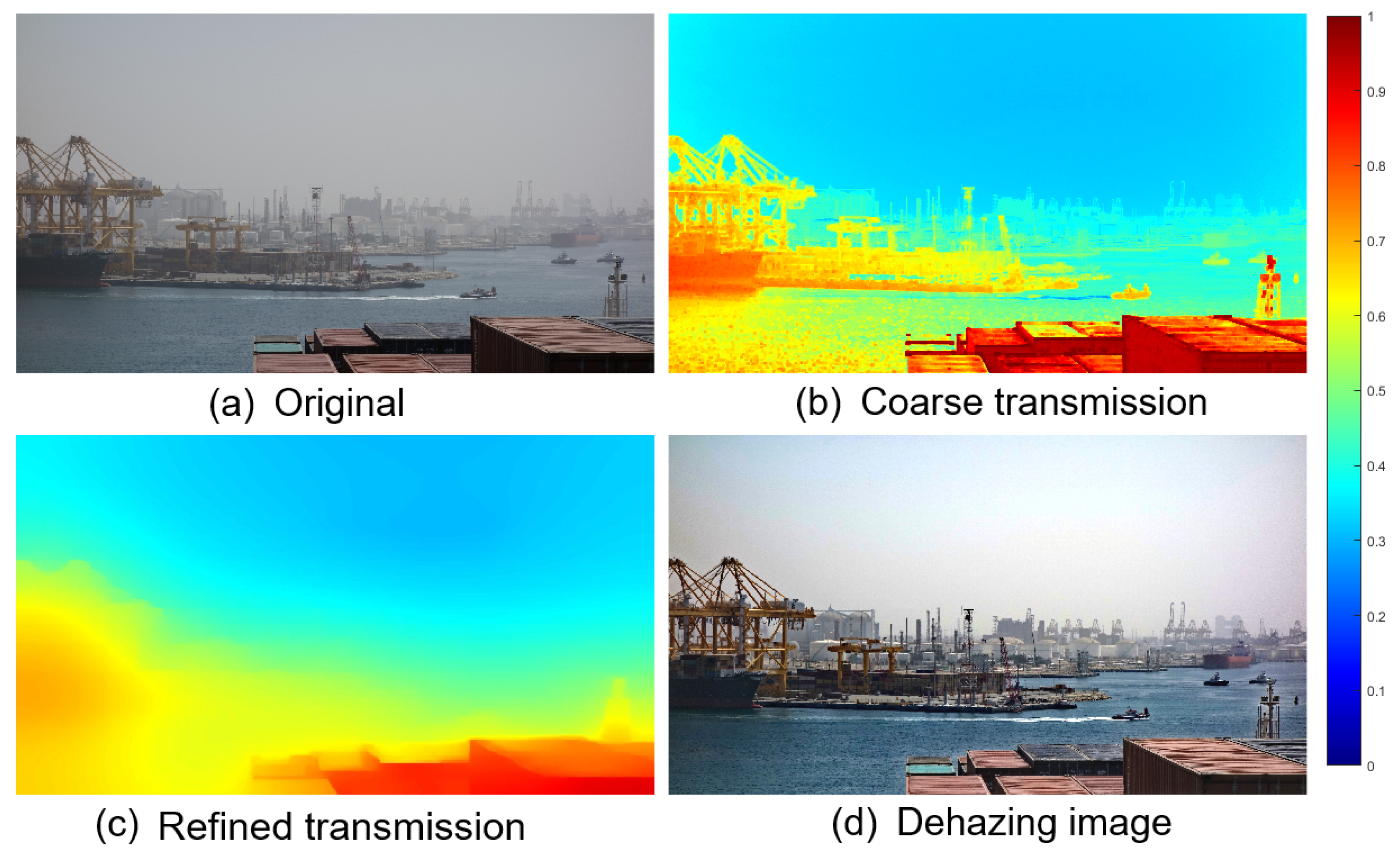
The proposed numerical method is effective to handle the nonconvex nonsmooth optimization problem Equation (15). After optimization, there are still some weak artifacts, guided filtering [34] can be used to enhance the edge structure information before the optimization process. The guided filtering filters the coarse transmission map through a guided image I , making the output transmission similar to the coarse transmission map in intensity, but the edges are enhanced to be similar to the guided image I . Once the final refined transmission map t is obtained, it is easy to yield the haze-free image J according to Equation (1). The whole optimization procedure is summarized in Algorithm 1. In addition, the procedure of transmission map refinement is illustrated in Figure 4.

5. Experimental Results and Analysis

5.1. Experimental Data

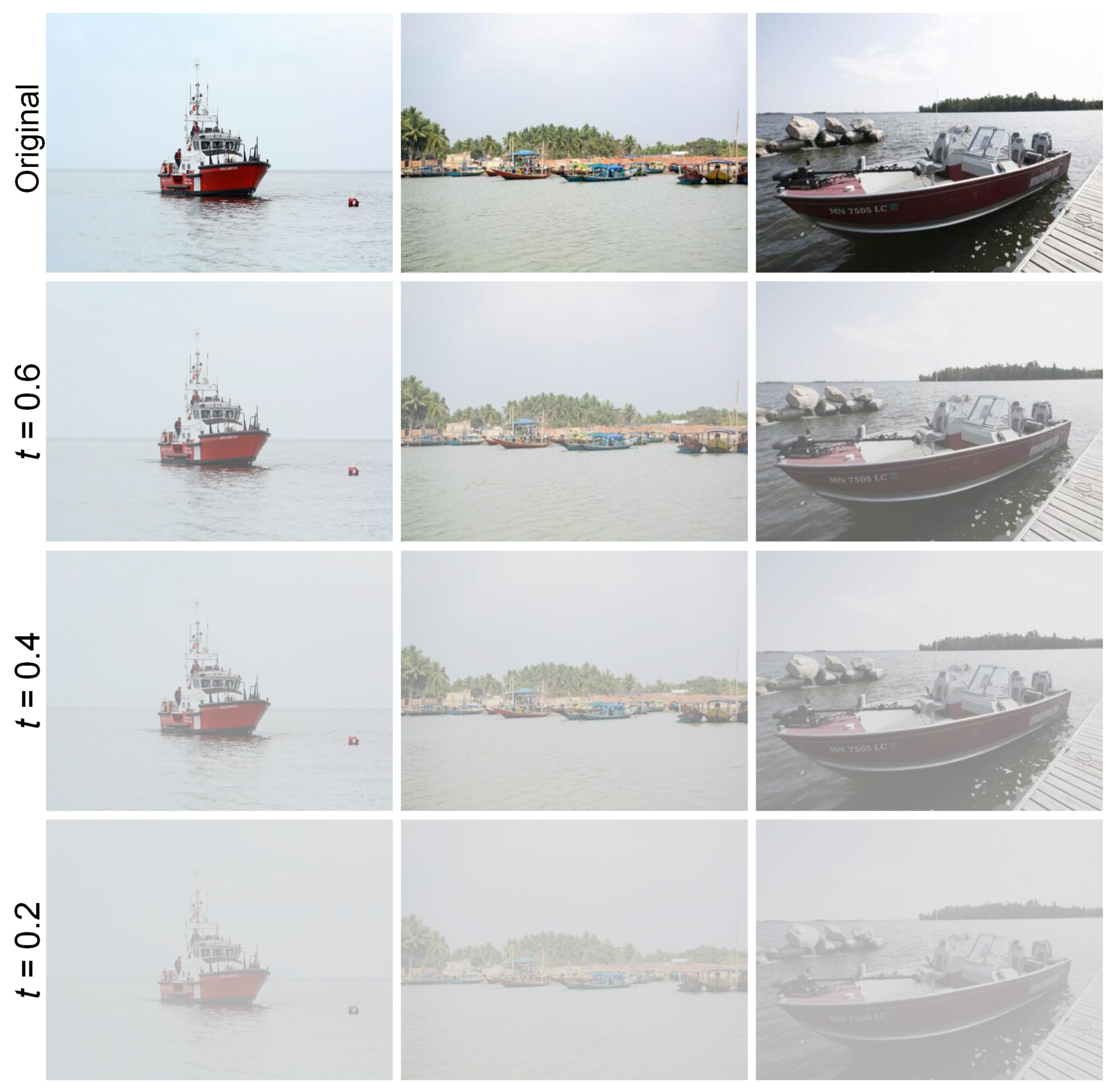
Experiments will be conducted on both synthetic and real-world images to verify the superior dehazing performance of our method. The synthetic images are generated based on a physical model. Specifically, we manually selected 100 high-quality maritime images from the public OverwaterHaze dataset [35] as ground truths. Examples of the synthetic data are shown in Figure 5, where the degraded images were generated using Equation (1) with t { 0.6 , 0.4 , 0.2 } and A = 0.8 . The real-world images are collected from actual hazy scenes and publicly available online datasets.

5.2. Experimental Settings

To verify the effectiveness and practicability of dehazing methods, numerous experiments are implemented on both synthetic and realistic hazy images. Our method will be compared with several state-of-the-art dehazing methods, including the dark channel prior (DCP) [11], non-local prior (Non-Local) [9], fusion of luminance and dark channel prior (F-LDCP) [13], gradient residual minimization (GRM) [36], all-in-one dehazing network (AOD-Net) [37], gated context aggregation network (GCANet) [38], and multi-scale convolutional neural network (MSCNN) [15]. In particular, the first four methods belong to the traditional dehazing methods. In contrast, the others are deep learning-driven dehazing methods. Analogous to previous variational dehazing methods, our method is also dependent on the optimal selections of (regularization) parameters. In our experiments, the tunable parameters were empirically optimized on the validation set and set as follows: λ 1 = 15 × 10 1 , λ 2 = 5 × 10 1 , λ 3 = 3 × 10 2 , λ 4 = 1 , λ 5 = 3 × 10 2 , β 1 = 1 × 10 1 , β 2 = 5 , and τ = 3.4 . Extensive experiments have demonstrated the effectiveness and robustness of these manually selected parameters under different hazy conditions. To achieve fair experimental comparisons, other dehazing methods will be implemented with the optimal parameters provided by the authors. Our experiments were conducted on a machine equipped with an Intel(R) Core(TM) i5-10600KF CPU @ 4.10GHz and an 11GB NVIDIA GeForce RTX 2080 TI, running Python 3.8 and PyTorch 1.6.0.

5.3. Dehazing Experiments on Synthetic Hazy Images

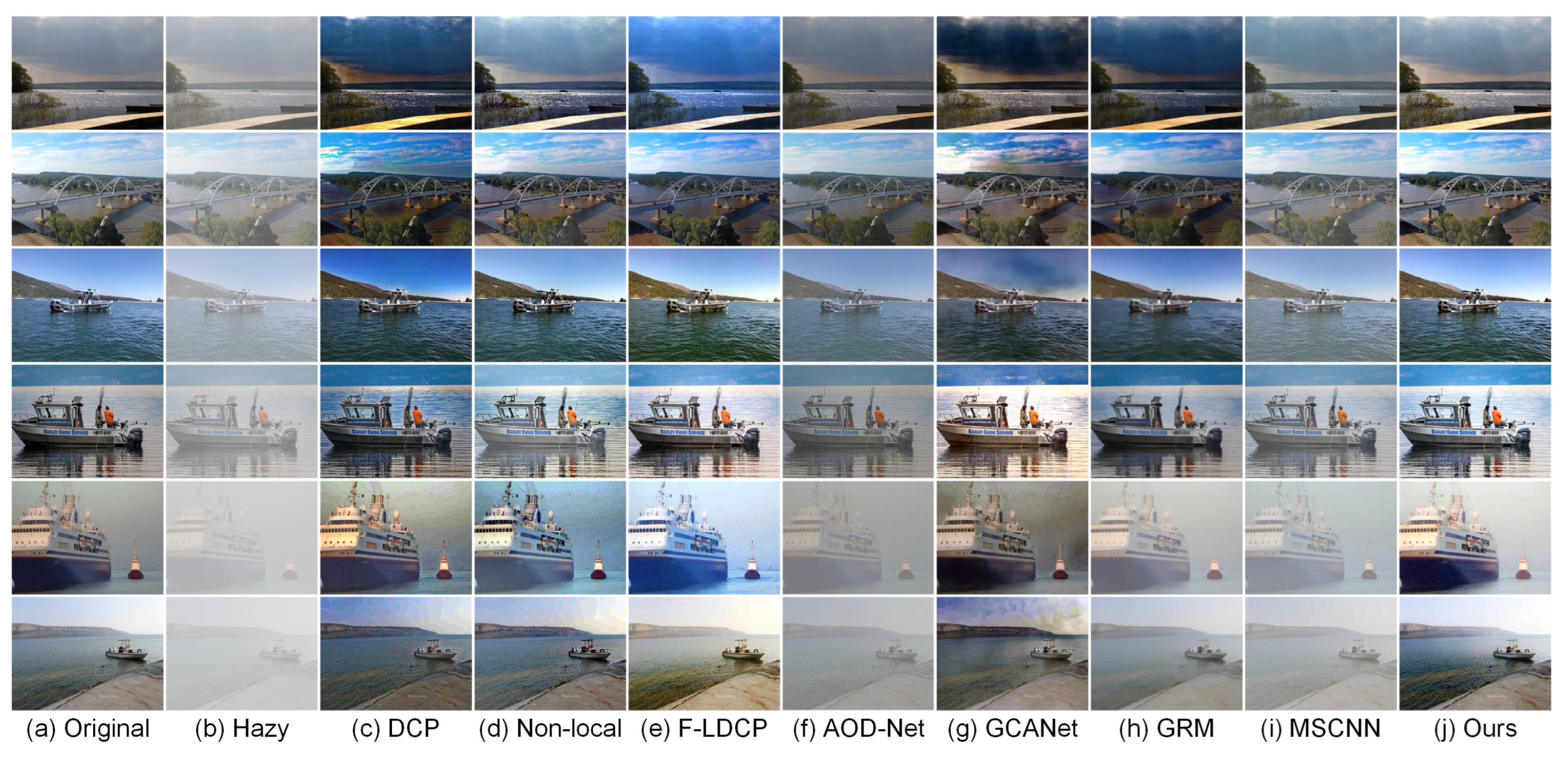
Comprehensive dehazing experiments on synthetic images will be conducted in this subsection. For the sake of better visual comparisons, several representative dehazing results are visually illustrated in Figure 6. It is obvious that DCP, Non-Local, and GCANet fail to generate the unnatural-looking restored images, due to the significant color distortion. Some unpleasant blocking artifacts are also produced in homogeneous regions (e.g., sky or water areas). Compared with these methods, F-LDCP could restore the hazy images with higher visual quality. However, the occurrence of color abnormality in homogeneous regions could create unnatural appearances. It is intractable to totally remove the haze effects through the AOD-Net, GRM, and MSCNN. The remaining haze has obviously degraded the image details and color appearance, leading to unsatisfactory and unstable visual quality. By comparison, our method can not only eliminate the effects of unwanted artifacts and color distortion, but also produce the most natural-looking restored images under different imaging conditions.
To quantitatively evaluate the imaging performance, PSNR [39], SSIM [40], FSIM [41], and FSIM c [41] are simultaneously exploited to compare our method with other dehazing methods. In theory, the higher scores essentially indicate the higher-quality dehazing results. The quantitative results are summarized in detail in Table 1. It can be found that our method generates the most optimal evaluation scores in all metrics. These superior imaging results mainly benefit from the robust transmission estimation and hybrid variational model.

5.4. Dehazing Experiments on Realistic Hazy Images

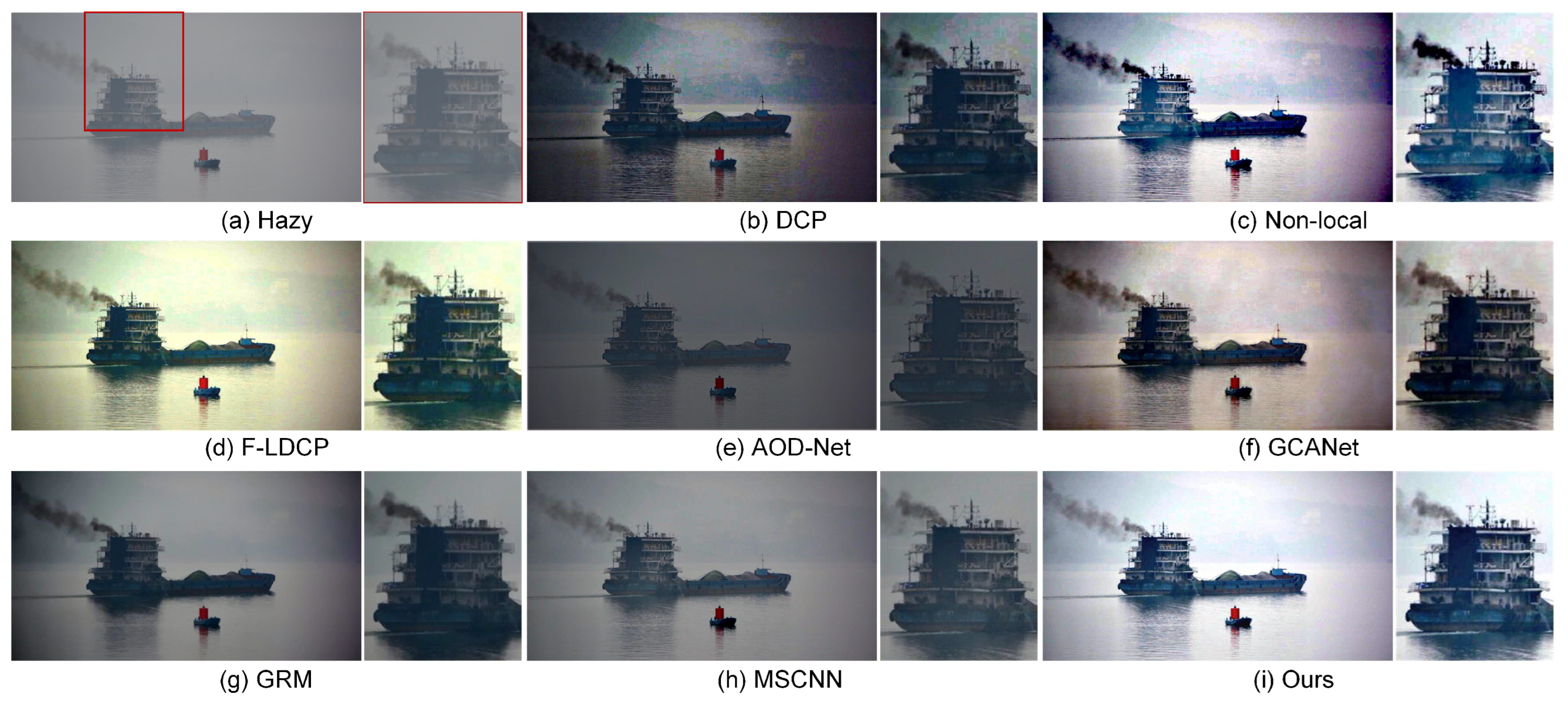
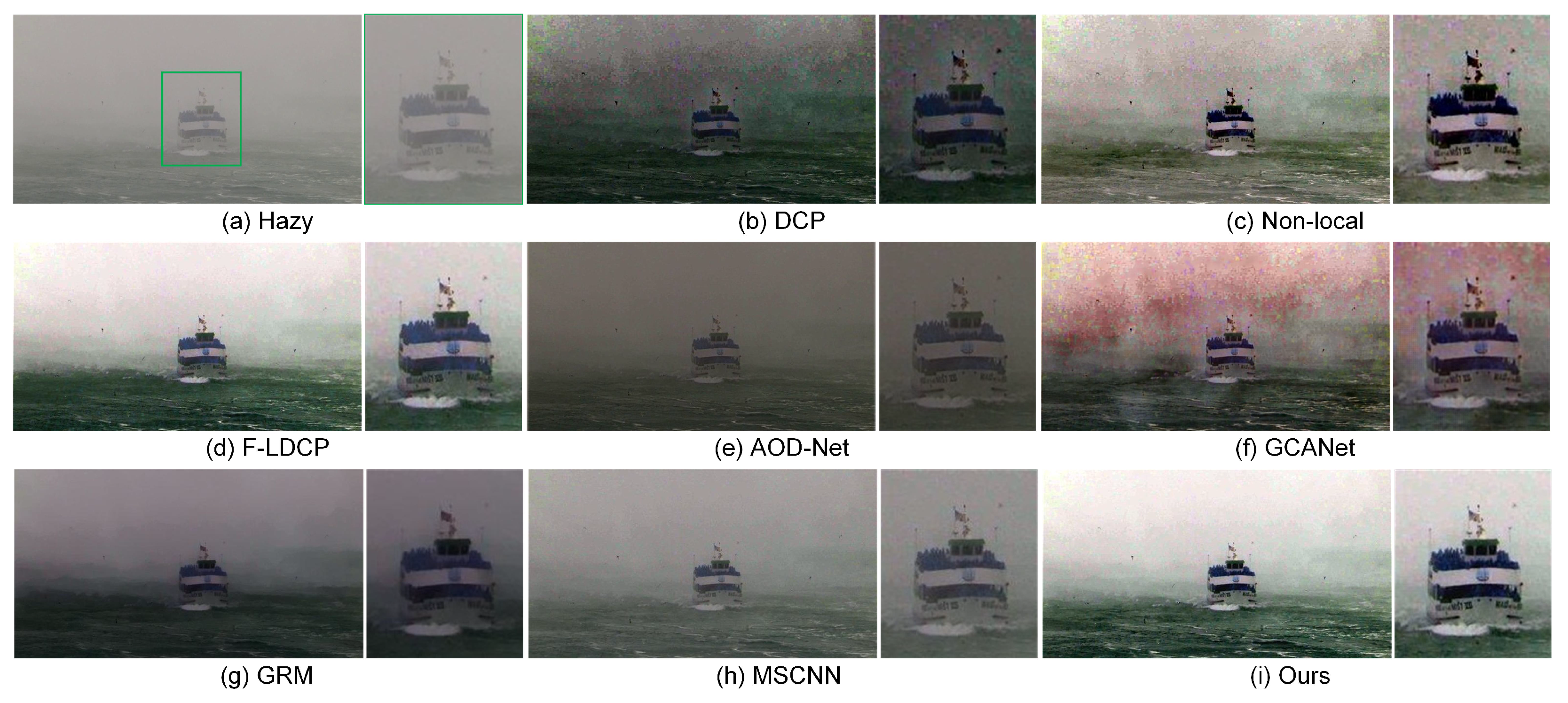
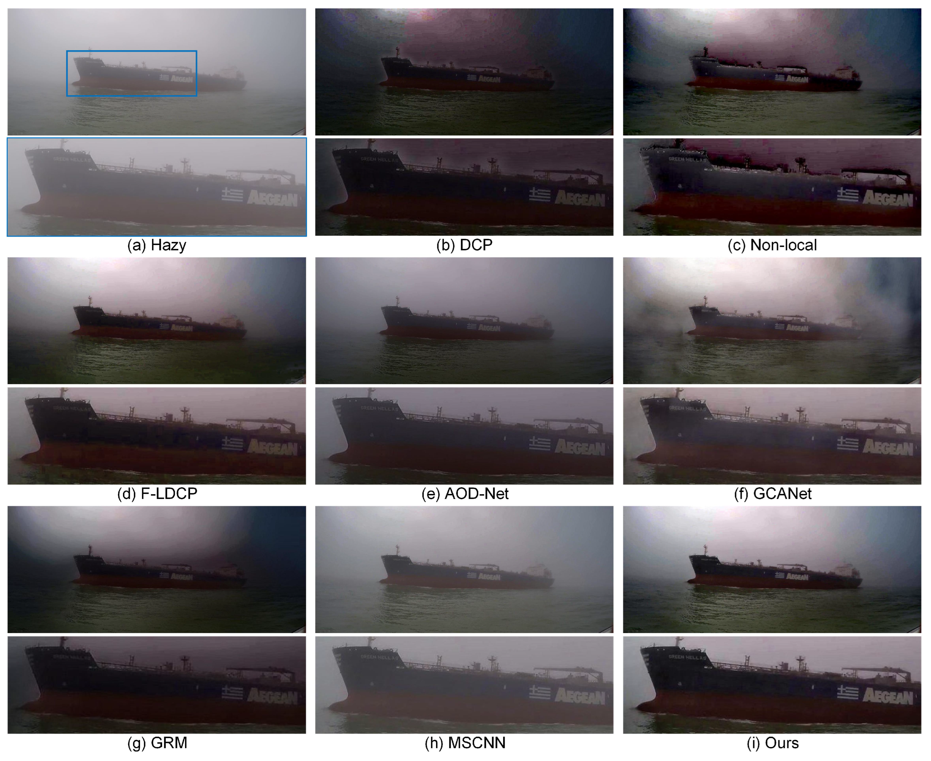
We further carry out several dehazing experiments on realistic hazy maritime images in this subsection. The visual comparisons of real-world dehazing methods are illustrated in Figure 7, Figure 8 and Figure 9. Unlike image dehazing in traditional urban transportation, the more general imaging scenarios with heterogeneous haze make maritime image dehazing more difficult in practice. The dehazing results illustrate that the competing methods fail to robustly reconstruct the hazy images. In particular, due to the improper prior assumptions, e.g., DCP and Non-Local, in sky and water areas, both DCP and Non-Local generate dehazed images with poor contrast or color distortion. In addition, some unwanted artifacts easily appear around the ships, resulting in image quality degradation. L-DCP is able to effectively remove the hazy effects. However, the restored results remain susceptible to the color shift interference, especially in the sky and water regions of relatively homogeneous colors. The negative effects, e.g., unwanted artifacts and color distortion, could also be observed in restored images generated by GCANet. By contrast, AOD-Net, GRM, and MSCNN are capable of eliminating the impact of haze and preserving the main image structures. However, the resulting restored images sometimes suffer from obvious degradation in intensity contrast. Compared with these state-of-the-art methods, our method has the capacity to effectively remove the hazing effects, eliminating the imaging contrast and preserving the color appearance. The visual image quality can be obviously improved under different scenarios. This is mainly due to the fact that our variational model performs well in accurately and robustly estimating the transmission map, which directly determines the reconstruction of hazy images.

5.5. Influences of Dehazing on Ship Detection

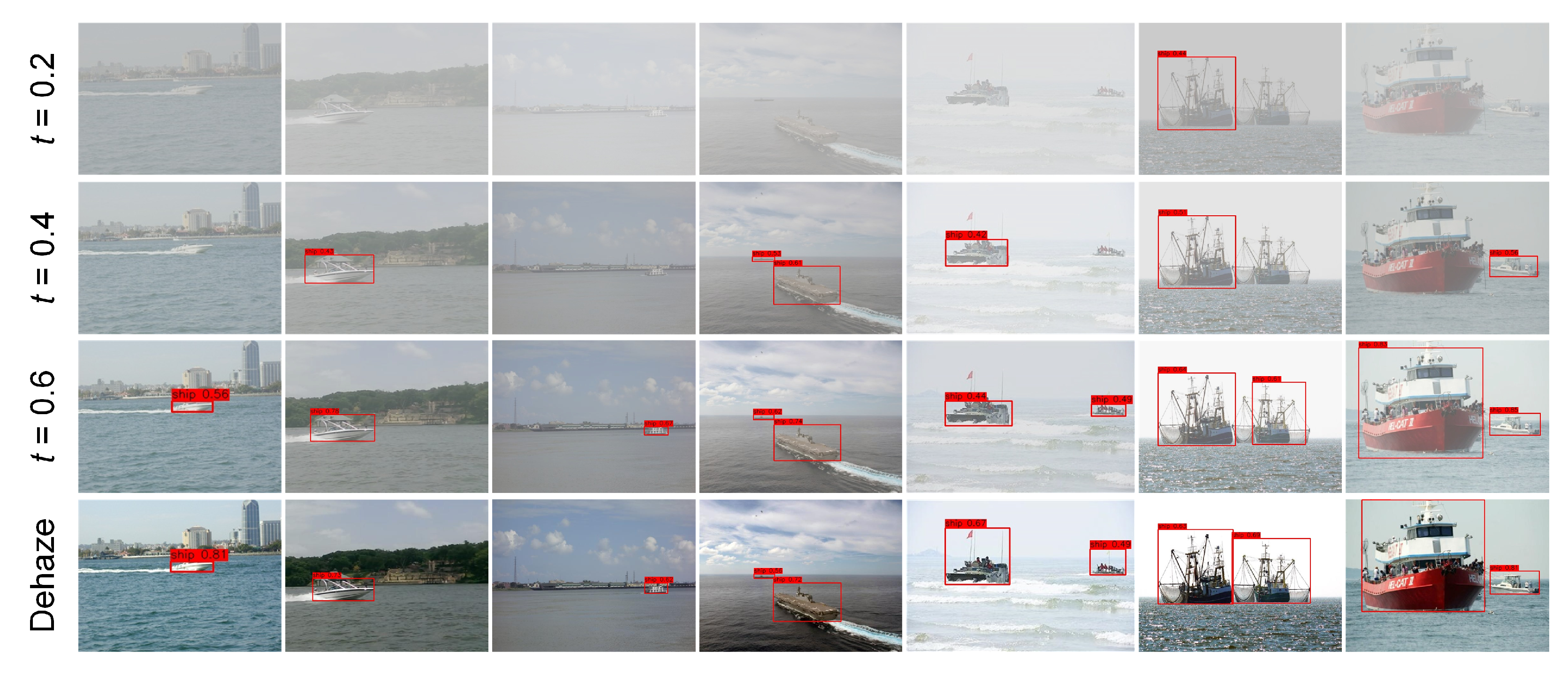
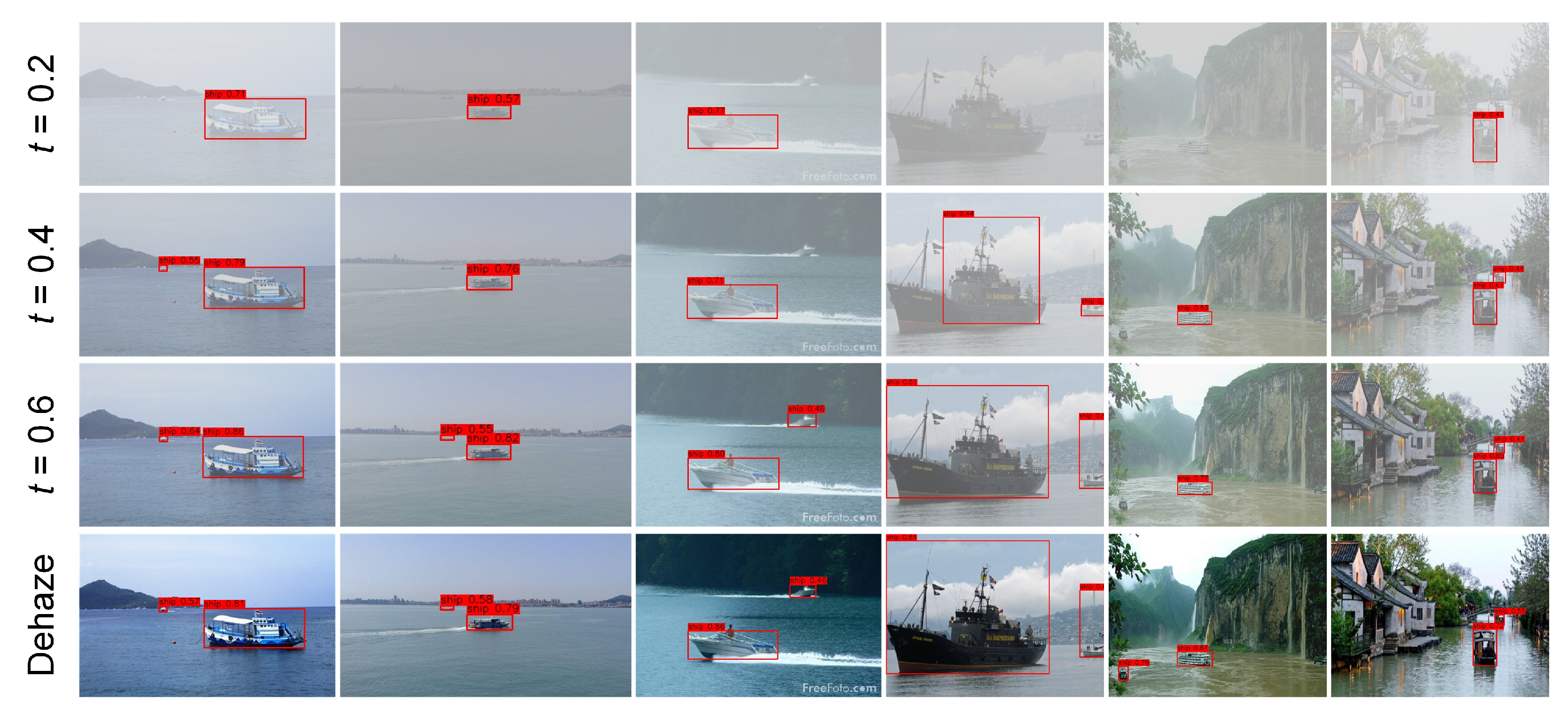
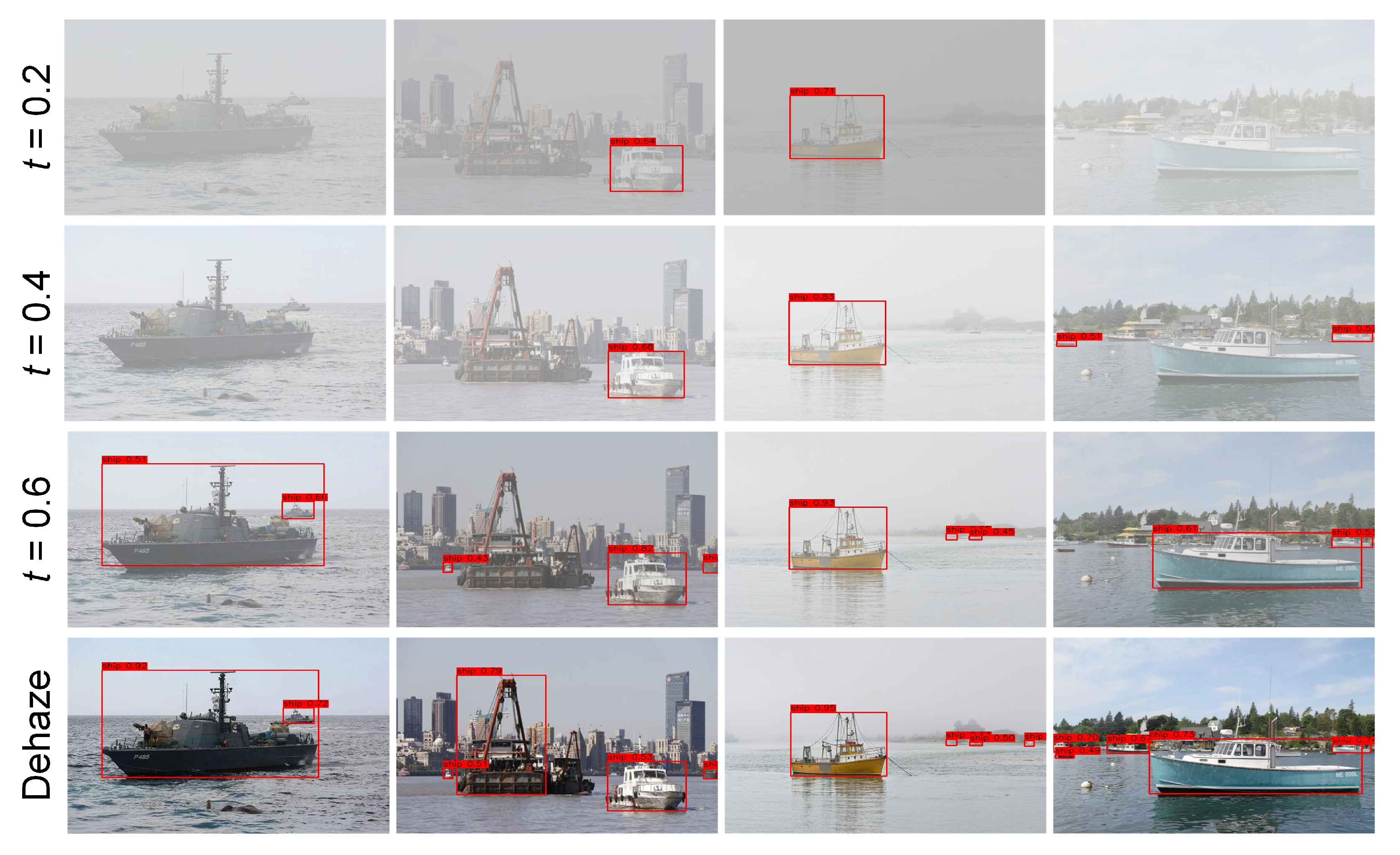
Object detection, recognition, and tracking provide reliable foundations for vehicle surveillance in video-empowered maritime transportation systems. However, the surveillance performance is strongly dependent on high-quality maritime images. There is thus a potential to employ our haze visibility-enhancement method to promote maritime vehicle surveillance under adverse hazy conditions. To investigate the influences of dehazing on ship detection, it is necessary to implement detection experiments on original hazy images and their restored versions. In particular, an efficient one-stage detector, YOLOv4 [42], which can achieve a good balance between detection accuracy and efficiency, is selected to detect maritime vehicles. The YOLOv4-based detection results are visually shown in Figure 10. In these hazy images, the visual information is inevitably obscured due to the hazing effects. Note that the training datasets often do not contain the degraded images collected under hazy conditions. The detection accuracy and robustness will be easily degraded accordingly. After the implementation of our method, the visual image quality will be significantly improved, resulting in high-quality ship detection results. More ship detection experiments under different imaging scenarios could be visually found in Figure 11, Figure 12 and Figure 13. It can be found that our method is capable of restoring the degraded images, leading to improved detection performance. Therefore, our method can be considered as a useful component for promoting surveillance of maritime vehicles in real-world scenarios during hazy weather conditions.

6. Conclusions

Visibility enhancement plays an essential role in guaranteeing the navigational safety of intelligent surface vehicles under hazy conditions. However, it is commonly intractable to accurately estimate the transmission map due to the enormous sky and water regions. To overcome this limitation, we first generated the coarse transmission map through weighing fuse transmission maps estimated by different methods. To further refine the coarse transmission map, a variational framework with hybrid regularizers was proposed. The proposed method could preserve important image structures and detailed information in various hazy conditions. Both synthetic and realistic experiments have illustrated that our method could perform superior quantitative and qualitative evaluations.
It is worth noting that our method is essentially a physically guided variational dehazing approach. The proposed method is relatively sensitive to certain parameters, such as the weights of the hybrid regularizers, which require careful tuning. These factors should be carefully considered when applying the method to real-time scenarios or large-scale datasets. Inspired by the successful combination of physical modeling and deep learning [43,44], future work could incorporate the proposed hybrid regularizers as constraints into the loss functions of deep learning-based dehazing models. This integration may reduce the model’s sensitivity to parameters and potentially further enhance imaging performance.

Author Contributions

Conceptualization, P.L., D.Q., and C.L.; Methodology, P.L., D.Q., C.L., D.W., and G.L.; Formal analysis, P.L. and D.Q.; Writing—original draft preparation, P.L., D.Q., and C.L.; Writing—review and editing, P.L., D.Q., and C.L.; Supervision, D.Q.; Project administration, P.L. and D.Q.; Funding acquisition, P.L. and D.Q. All authors have read and agreed to the published version of the manuscript.

Funding

This work was supported by the Major Project of Ningbo Science and Technology Innovation 2025.

Data Availability Statement

The data that support the findings of this study are available from the corresponding author upon reasonable request.

Conflicts of Interest

Authors Caofei Luo, Desong Wan, and Guilian Li were employed by the China E-Tech (Ningbo) Maritime Electronics Research Institute Co., Ltd. The remaining authors declare that the research was conducted in the absence of any commercial or financial relationships that could be construed as a potential conflict of interest.

References

  1. Liu, R.W.; Lu, Y.; Guo, Y.; Ren, W.; Zhu, F.; Lv, Y. AiOENet: All-in-one low-visibility enhancement to improve visual perception for intelligent marine vehicles under severe weather conditions. IEEE Trans. Intell. Veh. 2024, 9, 3811–3826. [Google Scholar] [CrossRef]
  2. Qiao, Y.; Yin, J.; Wang, W.; Duarte, F.; Yang, J.; Ratti, C. Survey of deep learning for autonomous surface vehicles in marine environments. IEEE Trans. Intell. Transp. Syst. 2023, 24, 3678–3701. [Google Scholar] [CrossRef]
  3. Stark, J.A. Adaptive image contrast enhancement using generalizations of histogram equalization. IEEE Trans. Image Process. 2000, 9, 889–896. [Google Scholar] [CrossRef] [PubMed]
  4. Soni, B.; Mathur, P. An improved image dehazing technique using CLAHE and guided filter. In Proceedings of the International Conference on Signal Processing and Integrated Networks (SPIN), Noida, India, 27–28 February 2020; pp. 902–907. [Google Scholar] [CrossRef]
  5. Zhou, J.; Zhou, F. Single image dehazing motivated by retinex theory. In Proceedings of the 2nd International Symposium on Instrumentation and Measurement, Sensor Network and Automation (IMSNA), Toronto, ON, Canada, 20–22 December 2013; pp. 243–247. [Google Scholar] [CrossRef]
  6. Land, E.H. The retinex. Am. Sci. 1964, 52, 247–264. [Google Scholar]
  7. Ancuti, C.O.; Ancuti, C. Single image dehazing by multi-scale fusion. IEEE Trans. Image Process. 2013, 22, 3271–3282. [Google Scholar] [CrossRef]
  8. Fattal, R. Single image dehazing. ACM Trans. Graph. 2008, 27, 1–9. [Google Scholar] [CrossRef]
  9. Berman, D.; Treibitz, T.; Avidan, S. Non-local image dehazing. In Proceedings of the IEEE Conference on Computer Vision and Pattern Recognition, Las Vegas, NV, USA, 27–30 June 2016; pp. 1674–1682. [Google Scholar] [CrossRef]
  10. Fattal, R. Dehazing using color-lines. ACM Trans. Graph. 2014, 34, 1–14. [Google Scholar] [CrossRef]
  11. He, K.; Sun, J.; Tang, X. Single image haze removal using dark channel prior. IEEE Trans. Pattern Anal. Mach. Intell. 2010, 33, 2341–2353. [Google Scholar] [CrossRef]
  12. Nair, D.; Sankaran, P. Color image dehazing using surround filter and dark channel prior. J. Vis. Commun. Image Represent. 2018, 50, 9–15. [Google Scholar] [CrossRef]
  13. Zhu, Y.; Tang, G.; Zhang, X.; Jiang, J.; Tian, Q. Haze removal method for natural restoration of images with sky. Neurocomputing 2018, 275, 499–510. [Google Scholar] [CrossRef]
  14. Cai, B.; Xu, X.; Jia, K.; Qing, C.; Tao, D. DehazeNet: An end-to-end system for single image haze removal. IEEE Trans. Image Process. 2016, 25, 5187–5198. [Google Scholar] [CrossRef] [PubMed]
  15. Ren, W.; Liu, S.; Zhang, H.; Pan, J.; Cao, X.; Yang, M.-H. Single image dehazing via multi-scale convolutional neural networks. In Proceedings of the European Conference on Computer Vision, Amsterdam, The Netherlands, 8–16 October 2016; pp. 154–169. [Google Scholar] [CrossRef]
  16. Golts, A.; Freedman, D.; Elad, M. Unsupervised single image dehazing using dark channel prior loss. IEEE Trans. Image Process. 2019, 29, 2692–2701. [Google Scholar] [CrossRef]
  17. Chen, W.; Fang, H.; Ding, J.; Kuo, S. PMHLD: Patch map-based hybrid learning DehazeNet for single image haze removal. IEEE Trans. Image Process. 2020, 29, 6773–6788. [Google Scholar] [CrossRef]
  18. Liu, R.W.; Guo, Y.; Lu, Y.; Chui, K.T.; Gupta, B.B. Deep network-enabled haze visibility enhancement for visual IoT-driven intelligent transportation systems. IEEE Trans. Ind. Inform. 2023, 19, 1581–1591. [Google Scholar] [CrossRef]
  19. Sahu, G.; Seal, A.; Bhattacharjee, D.; Frischer, R.; Krejcar, O. A novel parameter adaptive dual channel MSPCNN based single image dehazing for intelligent transportation systems. IEEE Trans. Intell. Transp. Syst. 2023, 24, 3027–3047. [Google Scholar] [CrossRef]
  20. Park, M.-H.; Choi, J.-H.; Lee, W.-J. Object detection for various types of vessels using the YOLO algorithm. J. Adv. Mar. Eng. Technol. 2024, 48, 81–88. [Google Scholar] [CrossRef]
  21. Liao, M.; Lu, Y.; Li, X.; Di, S.; Liang, W.; Chang, V. An unsupervised image dehazing method using patch-line and fuzzy clustering-line priors. IEEE Trans. Fuzzy Syst. 2024, 32, 3381–3395. [Google Scholar] [CrossRef]
  22. Guo, Y.; Lu, Y.; Liu, R.W.; Yang, M.; Chui, K.T. Low-light image enhancement with regularized illumination optimization and deep noise suppression. IEEE Access 2020, 8, 145297–145315. [Google Scholar] [CrossRef]
  23. Yang, M.; Nie, X.; Liu, R.W. Coarse-to-fine luminance estimation for low-light image enhancement in maritime video surveillance. In Proceedings of the IEEE Intelligent Transportation Systems Conference (ITSC), Auckland, New Zealand, 27–30 October 2019; pp. 299–304. [Google Scholar] [CrossRef]
  24. Bredies, K.; Kunisch, K.; Pock, T. Total generalized variation. SIAM J. Imaging Sci. 2010, 3, 492–526. [Google Scholar] [CrossRef]
  25. Xu, L.; Yan, Q.; Xia, Y.; Jia, J. Structure extraction from texture via relative total variation. ACM Trans. Graph. 2012, 31, 1–10. [Google Scholar] [CrossRef]
  26. McCartney, E.J. Optics of the Atmosphere: Scattering by Molecules and Particles; John Wiley and Sons, Inc.: New York, NY, USA, 1976. [Google Scholar] [CrossRef]
  27. Shu, Q.; Wu, C.; Xiao, Z.; Liu, R.W. Variational regularized transmission refinement for image dehazing. In Proceedings of the IEEE International Conference on Image Processing (ICIP), Taipei, Taiwan, 22–25 September 2019; pp. 2781–2785. [Google Scholar] [CrossRef]
  28. Gabay, D.; Mercier, B. A dual algorithm for the solution of nonlinear variational problems via finite element approximation. Comput. Math. Appl. 1976, 2, 17–40. [Google Scholar] [CrossRef]
  29. Goldstein, T.; Osher, S. The split Bregman method for l1-regularized problems. SIAM J. Imaging Sci. 2009, 2, 323–343. [Google Scholar] [CrossRef]
  30. Beck, A.; Teboulle, M. A fast iterative shrinkage-thresholding algorithm for linear inverse problems. SIAM J. Imaging Sci. 2009, 2, 183–202. [Google Scholar] [CrossRef]
  31. Chambolle, A.; Pock, T. A first-order primal-dual algorithm for convex problems with applications to imaging. J. Math. Imaging Vis. 2011, 40, 120–145. [Google Scholar] [CrossRef]
  32. Condat, L. A primal–dual splitting method for convex optimization involving Lipschitzian, proximable and linear composite terms. J. Optim. Theory Appl. 2013, 158, 460–479. [Google Scholar] [CrossRef]
  33. Liu, Q.; Xiong, B.; Yang, D.; Zhang, M. A generalized relative total variation method for image smoothing. Multimed. Tools Appl. 2016, 75, 7909–7930. [Google Scholar] [CrossRef]
  34. He, K.; Sun, J.; Tang, X. Guided image filtering. IEEE Trans. Pattern Anal. Mach. Intell. 2013, 35, 1397–1409. [Google Scholar] [CrossRef]
  35. Zheng, S.; Sun, J.; Liu, Q.; Qi, Y.; Zhang, S. Overwater image dehazing via cycle-consistent generative adversarial network. In Proceedings of the Asian Conference on Computer Vision, Kyoto, Japan, 30 November–4 December 2020. [Google Scholar]
  36. Chen, C.; Do, M.N.; Wang, J. Robust image and video dehazing with visual artifact suppression via gradient residual minimization. In Computer Vision—ECCV 2016; Springer: Cham, Switzerland, 2016. [Google Scholar] [CrossRef]
  37. Li, B.; Peng, X.; Wang, Z.; Xu, J.; Feng, D. AOD-Net: All-in-one dehazing network. In Proceedings of the IEEE International Conference on Computer Vision, Venice, Italy, 22–29 October 2017; pp. 4770–4778. [Google Scholar] [CrossRef]
  38. Chen, D.; He, M.; Fan, Q.; Liao, J.; Zhang, L.; Hou, D.; Yuan, L.; Hua, G. Gated context aggregation network for image dehazing and deraining. In Proceedings of the IEEE Winter Conference on Applications of Computer Vision (WACV), Waikoloa, HI, USA, 7–10 January 2019; pp. 1375–1383. [Google Scholar] [CrossRef]
  39. Wang, Z.; Bovik, A.C. Mean squared error: Love it or leave it? A new look at signal fidelity measures. IEEE Signal Process. Mag. 2009, 26, 98–117. [Google Scholar] [CrossRef]
  40. Wang, Z.; Bovik, A.C.; Sheikh, H.R.; Simoncelli, E.P. Image quality assessment: From error visibility to structural similarity. IEEE Trans. Image Process. 2004, 13, 600–612. [Google Scholar] [CrossRef]
  41. Zhang, L.; Zhang, L.; Mou, X.; Zhang, D. FSIM: A feature similarity index for image quality assessment. IEEE Trans. Image Process. 2011, 20, 2378–2386. [Google Scholar] [CrossRef] [PubMed]
  42. Bochkovskiy, A.; Wang, C.Y.; Liao, H.Y.M. YOLOv4: Optimal speed and accuracy of object detection. arXiv 2020, arXiv:2004.10934. [Google Scholar] [CrossRef]
  43. Xu, J.; Hu, X.; Zhu, L.; Heng, P.-A. Unifying physically-informed weather priors in a single model for image restoration across multiple adverse weather conditions. IEEE Trans. Circuits Syst. Video Technol. 2025, 1. [Google Scholar] [CrossRef]
  44. He, W.; Wang, M.; Chen, Y.; Zhang, H. An unsupervised dehazing network with hybrid prior constraints for hyperspectral image. IEEE Trans. Geosci. Remote Sens. 2024, 62, 5514715. [Google Scholar] [CrossRef]
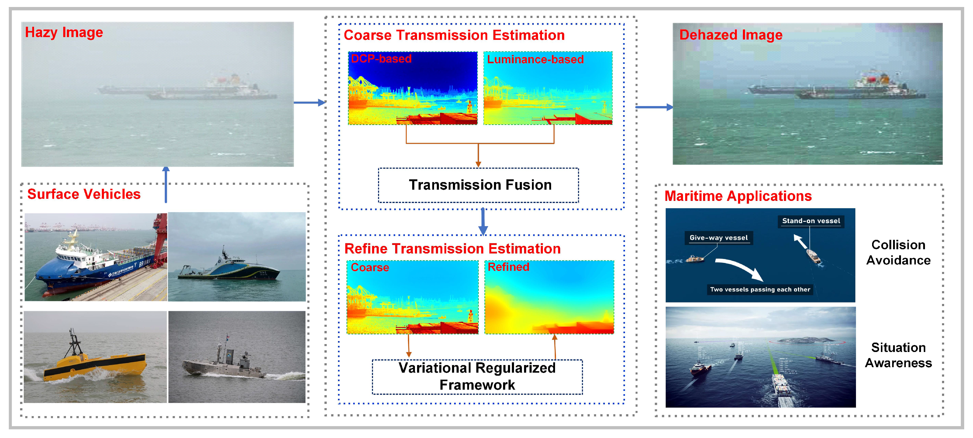
Figure 1. The flowchart of our proposed hybrid regularized variational dehazing framework for maritime intelligent surface vehicles under hazy conditions is shown. The method consists of two main processes. The first is the fusion of multiple transmission maps to generate a coarse transmission map, and the second is the optimization of this coarse map within a joint variational framework. This workflow enhances visual perception, which helps improve situational awareness, reduce collision risk, and ultimately enhance traffic safety in complex navigation environments.
Jmse 13 01991 g001
Figure 2. Examples of DCP dehazing. From left to right: (a) original hazy maritime image, (b) transmission map estimated by DCP, (c) dehazed image generated by DCP. It is obvious that the result inevitably suffers from serious overly dark appearances and halo artifacts.
Jmse 13 01991 g002
Figure 3. Fusion process of the coarse transmission map. From top-left to bottom-right: (a) transmission map estimated by DCP, (b) transmission map estimated by luminance-based model, (c) weight ω ( x ) , (d) coarse transmission map.
Jmse 13 01991 g003
Figure 4. The procedure of transmission map refinement. From top-left to bottom-right: (a) original hazy maritime image, (b) coarse transmission map, (c) refined transmission map, and (d) dehazed image generated by our method.
Jmse 13 01991 g004
Figure 5. Different haze levels of realistic maritime images. From top to bottom: original image, hazy maritime image synthesized by t = 0.6 , t = 0.4 and t = 0.2 , respectively.
Jmse 13 01991 g005
Figure 6. Dehazing experiments on several synthetically degraded images. From left to right: (a) original images, (b) synthesized hazy image by t (from top to bottom: t = 0.6 , 0.6 , 0.4 , 0.4 , 0.2 , 0.2 ), dehazed results generated by (c) DCP [11], (d)Non-Local [9], (e) F-LDCP [13], (f) AOD-Net [37], (g) GCANet [38], (h) GRM [36], (i) MSCNN [15], and (j) ours, respectively. It is obvious that our method could generate more natural-looking images compared with other competing methods. The higher-quality images are beneficial for post-processing steps in maritime applications, such as object detection, recognition, and tracking, etc.
Jmse 13 01991 g006
Figure 7. Realistic dehazing results. From top-left to bottom-right: (a) original images, dehazed images by (b) DCP [11], (c) Non-Local [9], (d) F-LDCP [13], (e) AOD-Net [37], (f) GCANet [38], (g) GRM [36], (h) MSCNN [15], and (i) ours, respectively. It was found that our method could restore the important structures and suppress unwanted artifacts. The visual quality could be accordingly improved owing to the joint variational framework considered in this work. The other competing methods easily suffer from potential limitations, e.g., color distortion and texture blurring, etc.
Jmse 13 01991 g007
Figure 8. Realistic dehazing results. From top-left to bottom-right: (a) original images, dehazed images by (b) DCP [11], (c) Non-Local [9], (d) F-LDCP [13], (e) AOD-Net [37], (f) GCANet [38], (g) GRM [36], (h) MSCNN [15], and (i) ours, respectively. Our method is capable of restoring the important object from the low-quality and hazy background. The dehazed image with visual quality improvement would have a positive influence on situational awareness for intelligent surface vehicles.
Jmse 13 01991 g008
Figure 9. Realistic dehazing results. From top-left to bottom-right: (a) original images, dehazed images by (b) DCP [11], (c) Non-Local [9], (d) F-LDCP [13], (e) AOD-Net [37], (f) GCANet [38], (g) GRM [36], (h) MSCNN [15], and (i) ours, respectively. Our method thus has the capacity to further improving the image quality compared with other dehazing methods.
Jmse 13 01991 g009
Figure 10. The YOLOv4-based ship detection results from original hazy images (Top) and our dehazed images (Bottom). It can be found that dehazing can significantly improve the accuracy and robustness of ship detection under different imaging conditions.
Jmse 13 01991 g010
Figure 11. The YOLOv4-based ship detection results from realistic maritime images with different haze levels (t = 0.2, 0.4, 0.6) and our dehazed images for intelligent surface vehicles. These images are from simple scenarios, characterized by single objects or a clear background.
Jmse 13 01991 g011
Figure 12. The YOLOv4-based ship detection results from realistic maritime images with different haze levels (t = 0.2, 0.4, 0.6) and our dehazed images for intelligent surface vehicles. These images are characterized by multiple scales or complex backgrounds.
Jmse 13 01991 g012
Figure 13. The YOLOv4-based ship detection results from realistic maritime images with different haze levels (t = 0.2, 0.4, 0.6) and our dehazed images for intelligent surface vehicles. These images are from complex scenarios, characterized by multiple objects or small objects.
Jmse 13 01991 g013
Table 1. PSNR, SSIM, FSIM, and FSIM C comparisons (mean ± std) of all methods based on synthesized hazy maritime images. The best results are highlighted in bold.
MethodsPSNRSSIMFSIM FSIM C
DCP [11]14.70 ± 2.090.807 ± 0.0440.913 ± 0.0280.909 ± 0.029
Non-local [9]18.53 ± 2.720.862 ± 0.0510.926 ± 0.0340.922 ± 0.034
F-LDCP [13]20.91 ± 2.120.916 ± 0.0340.956 ± 0.0130.951 ± 0.015
GRM [36]16.88 ± 1.420.761 ± 0.0780.885 ± 0.0330.882 ± 0.033
AOD-Net [37]18.15 ± 1.010.870 ± 0.0340.884 ± 0.0170.882 ± 0.017
GCANet [38]19.07 ± 4.370.874 ± 0.0690.938 ± 0.0370.930 ± 0.041
MSCNN [15]18.71 ± 2.140.874 ± 0.0440.939 ± 0.0140.937 ± 0.014
Ours21.92 ± 2.350.933 ± 0.0190.971 ± 0.0120.967 ± 0.013
Disclaimer/Publisher’s Note: The statements, opinions and data contained in all publications are solely those of the individual author(s) and contributor(s) and not of MDPI and/or the editor(s). MDPI and/or the editor(s) disclaim responsibility for any injury to people or property resulting from any ideas, methods, instructions or products referred to in the content.