Abstract
Hydrogen fuel presents a promising pathway for achieving long-term decarbonization in the maritime sector. However, its use in diesel engines introduces challenges due to high reactivity, leading to increased NOx emissions and combustion instability. The aim of this study is to identify settings so that the investigated engine operates with 60% hydrogen energy fraction at high load through CFD modelling. The model is utilized to simulate a four-stroke, 10.5 MW marine engine at 90% load, incorporating 60% hydrogen injection by energy at the engine intake port. The CFD model is verified using experimental data from diesel operation of the marine engine and hydrogen operation of a light-duty engine. The engine performance was determined and detailed emissions analysis was conducted, including NO, NO2, HO2, and OH. The findings indicate a substantial rise in NOx emissions as opposed to diesel operation, due to elevated combustion temperatures and increased residence time at elevated temperature of the mixture in-cylinder. The presence of HO2 and OH highlights critical zones of combustion, which contribute to operational stability. The novelty of this study is supported by the examination of the high hydrogen energy fraction, the advanced emissions analysis, and the insights into the emissions–performance trade-offs in hydrogen-fueled dual-fuel marine engines. The results offer guidance for the development of sustainable hydrogen-based marine propulsion systems.
1. Introduction
The International Maritime Organization (IMO) released its latest greenhouse gas (GHG) strategy, showing a strong ambition to gradually cut GHG emissions from international shipping. Relative to 2008 levels, the new strategy set a preliminary target to reduce GHG by 20% by 2030, followed by a greater reduction of 70% by 2040. Notably, the ultimate goal is to reach net zero GHG in the maritime sector by 2050. To meet the requirement of the IMO, the maritime sector is undergoing an alternative fuel exploration towards decarbonisation transition [1]. Hydrogen is considered a promising candidate due to its potential for carbon neutral combustion [2]. Recent research has demonstrated the feasibility of hydrogen-fuelled engines in maritime applications, highlighting their potential to meet both environmental and operational requirements [3].
However, integrating hydrogen into marine compression ignition engines presents several technical challenges like ignition difficulty (requiring pilot fuel), overly rapid combustion (knocking rick), high combustion temperature (leading to NOx emissions), and complex supply system, primarily due to hydrogen’s distinct physical and chemical properties [4]. Notably, hydrogen’s high auto-ignition temperature necessitates advanced ignition strategies to ensure reliable combustion [5]. One effective approach is dual-fuel operation, where hydrogen is used in conjunction with a more reactive pilot fuel, such as diesel, to initiate combustion [6]. In this configuration, hydrogen is utilised in the engine either through port or direct injection methods. Each method has unique implications for engine performance, combustion characteristics, and emission profiles [7].
Experimental studies have investigated the effects of hydrogen port injection on engine performance and emissions [8]. For instance, research has shown that hydrogen supplementation can lead to increased in-cylinder pressures and temperatures, which, while enhancing efficiency, may also result in elevated nitrogen oxide (NOx) emissions [9,10]. The experiment conducted by Li et al. reveals that increasing hydrogen addition percentage in a hydrogen–diesel dual-fuel engine advances maximum pressure angle [11]. Köse et al. [12] experimentally found that adding hydrogen from 2.5% vol to 7.5% vol via PFI to diesel engine increases engine torque, power, and thermal efficiency. These findings underscore the need for optimised injection strategies and engine calibration to balance performance improvement with emission control [13].
Numerical simulations have further explored the combustion dynamics of hydrogen-enriched dual-fuel engines [14]. Studies utilising advanced modelling techniques have examined various parameters, such as injection timing [15,16,17], compression ratios, and fuel mixtures [18,19], to assess their impact on combustion stability and knock tendencies. The authors’ previous study [20] suggested that, at 60% hydrogen energy fraction condition of a premixed hydrogen–diesel dual fuel engine, the optimal start of injection of high reactivity diesel is 8 °CA BTDC, which enables both high indicated thermal efficiency and hydrogen combustion efficiency. Sharma and Dhar [21] investigated numerically the effect of compression ratio on hydrogen–diesel dual-fuel combustion, reporting a 25% hydrogen maximum replacement reduction when increasing compression ratio from 14.5 to 19.5. These simulations provide valuable insights into optimising engine design and operational parameters for effective hydrogen use in marine applications. However, most current studies focus on low- and medium-hydrogen energy fraction combustion, typically employing a RANS model for turbulence modelling. As a result, the combustion characteristics at the high hydrogen energy fraction remain insufficiently understood, and the accuracy of flame capture is limited.
This study aims to address the in-cylinder performance of a diesel–hydrogen dual-fuel marine engine operating at 60% hydrogen energy fraction through CFD modelling.
The novelty of this stems from the examination of high hydrogen energy fractions; exploration of dual-fuel combustion with hydrogen in marine engines; identification of combustion conditions that lead to increased NOx emissions and design of mitigation measures. The significance of the study pertains to the absence of research focusing specifically on dual-fuel premixed hydrogen combustion in marine engines despite recent advancements in hydrogen combustion. Given the potential benefits of retrofitting existing marine engines for hydrogen use, this area warrants further investigation to develop practical solutions that align with environmental objectives and operational demands.
2. Materials and Methods
The methodological framework for developing the numerical model is described by Karvounis and Theotokatos [22,23,24] incorporating validation of the models with experimental data for small-bore engines and extending the model parameters to large-bore marine engines that are the main focus of the study and presented in Figure 1. The process begins with Step-1, defining the operational features and marine engine settings to establish essential input parameters. In Step-2, a computational fluid dynamics (CFD) model for diesel operation of the engine is developed utilizing CONVERGE 3.1 commercial software, considering direct diesel injection. Boundary conditions, including cylinder wall, head, and piston temperatures, are derived from existing literature. The sub-model for injection is calibrated using engine trials data. Step-3 entails a grid sensitivity analysis to optimise the balance between computational error and resource efficiency.
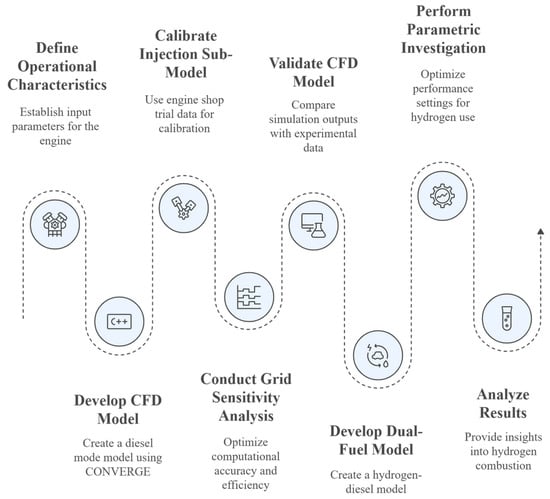
Figure 1.
CFD model development flowchart.
Step-4 validates the developed CFD model by comparing simulation outputs with experimental data for diesel mode operation. In Step-5, the validated CFD model serves as a baseline for developing the dual-fuel hydrogen–diesel model while maintaining consistent solver settings, geometry, grid structure, and reaction mechanisms. In this configuration, hydrogen is injected early in the port manifold, undergoing premixed combustion, while diesel is directly injected into the cylinder to initiate ignition and sustain combustion. The port-injected hydrogen is assumed to achieve a homogeneous in-cylinder mixture at the beginning of the closed cycle. Step-6 involves a parametric investigation, to end up in the adequate performance settings to accommodate 60% hydrogen in the marine engine of consideration. Finally, Step-7 analyses the results to provide insights into high-load hydrogen combustion characteristics in marine engines. The study is focused on a nine-cylinder, four-stroke marine engine, with its specifications detailed in Table 1.

Table 1.
Marine engine characteristics.
To develop the CFD models, the following assumptions were made:
- A homogeneous air–hydrogen mixture is considered;
- Diesel fuel is directly injected into the cylinder following a trapezoidal injection pulse;
- The working medium is assumed to behave as an ideal gas, which adequately represents its thermodynamic behavior;
- All nine cylinders are assumed to exhibit identical performance to the simulated one;
- The simulation entails the closed cycle of the engine.
The governing equations for the CFD simulation include the continuity, momentum, energy, and species transport equations, which are presented as follows.
where, ρ, t and u pertain to the density, time, and velocity vector, respectively.
where p represents the pressure, g is the gravity acceleration vector, and τ refers to the viscous stress tensor.
where E is the total mass-based energy, kt refers to the turbulent kinetic energy, and T represents the temperature, whereas S refers to the source term in (W/m3),
where Yi refers to the mass fraction of species i, D is the diffusion coefficient, and Ri represents the source term for species reaction.
The developed CFD model incorporates large eddy simulations that use a viscous one-equation turbulence model that solves single transport equation for the turbulent kinetic energy as presented below.
where μ is the molecular viscosity, μt is the turbulent kinetic viscosity, Pk is the production of turbulent kinetic energy, and ε the dissipation rate of turbulent kinetic energy. The wall modelling takes place through a Werner and Wengle model [25] that approximates the velocity profile near solid boundaries without fully resolving the viscous sublayer, suitable for high Reynolds flows as in internal combustion engines. The LES constants include sub-grid scale eps, with a sub-grid scale kinetic energy of 1 and 2 respectively. The viscosity constant is 0.05 and the droplet turbulent dispersion constant is 0.03.
The sub-model for droplet breakup is represented by the Kelvin–Helmholtz and Rayleigh–Taylor [26] instability models, which determine the timescale of droplet breakup and wavelength.
Other sub-models utilised in the model include the Zeldovich for NOx emissions calculation [27]. In this study, the extended version of Zeldovich is considered, capturing the formation of NOx at temperatures below 1800 K, which is considered the NOx cut-off temperature. A negative temperature coefficient model was used for droplet collision [28] and a Han and Reitz model for heat transfer [29]. For the turbulence modelling, large eddy simulations (LES) are utilised as they present greater accuracy as opposed to Reynolds averaged models with the expense of computational effort.
Since the study is focused on the in-cylinder behaviour of dual-fuel combustion, turbulence is selected to be modelled using large eddy simulations as they retain several accuracy benefits with the expense of computational effort [30].
2.1. Experimental Validation
The numerical model is validated by comparing the pressure data in-cylinder retrieved from shipboard measurements, which are corrected to remove offsets [31] and subsequently utilized to calculate the heat release rate. Figure 2 displays the simulated and measured in-cylinder pressure and heat release rate at a 90%-load condition for diesel operation of a marine engine and dual-fuel operation of a high-speed engine. For the marine engine, the validation conducted for diesel operation and the calculated error for the peak in-cylinder pressure is approximately 1%, while the crank angle at peak pressure shows a 6% deviation. For the hydrogen operation, the numerical model is validated against experimental data obtained from Tujimura and Suzuki [32] for a small-bore engine operating with 14% and 24% hydrogen energy fraction. The RMSE in between the measured and calculated in-cylinder pressure is 5 bar. The reported unburned hydrogen (hydrogen slip) for the experimental engine is 27% and 30% for 14% and 24% hydrogen energy fraction (HEF), respectively, whereas CFD predicted 31% and 33%, resulting in a 9–13% error. Detailed errors are presented in Table 2. The variations in the pressure and heat release rate profile pertain to inhomogeneity of the mixture in the experimental process, whereas for the simulation, the air–hydrogen mixture is considered fully homogenous. Further to the inhomogeneity, what was missing as input is the injection rate shape that is found to affect the combustion behavior. Further validation is provided in Table A1 of the Appendix A for the dual-fuel operation of the marine engine with natural gas using shop test trial data. Overall, the model demonstrates satisfactory error with the measured data in terms of both in-cylinder pressure and heat release rate. The selected kinetics mechanism is the one described by Andrae and Head used for diesel surrogate combustion [33]. The same reaction mechanism is employed for single and dual-fuel configurations, as it adequately captures hydrogen fuel oxidation to water [20]. Benchmarking between the experimental and simulated results confirms the validity of the chosen reaction mechanism, and despite the noted discrepancies, the numerical model is deemed sufficiently accurate for representing the engine’s behavior.
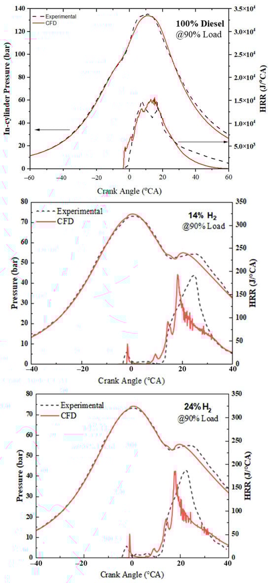
Figure 2.
In-cylinder pressure and heat release rate validation for the diesel operation at 90% load for the marine engine and 14% and 24% hydrogen operation for the small engine at 90% load.
Table 2.
Simulated and measured errors on cylinder pressure, heat release rate and hydrogen fuel combustion efficiency for the validation cases with light duty engine.
2.2. Grid Sensitivity
In order to decide upon the best-performing grid and required computational effort, a grid sensitivity study is conducted with grid sizes of 6, 4, 2, and 1mm.
Figure 3 provides a grid sensitivity analysis, illustrating how computational grid resolution impacts pressure, heat release rate, as well as temperature, and NOx emissions. According to the analysis, the best-performing grid is G3 with 2 mm final element size. More detailed analysis is provided in previous studies of the authors [22,23,24]. Table 3 incorporates all the characteristics of the computational grid and simulation parameters.
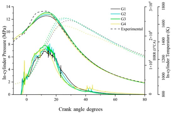
Figure 3.
Grid sensitivity for in-cylinder pressure, heat release rate, and in-cylinder temperature and NOx contours for different grids.
Table 3.
Computational grids characteristics and simulation parameters.
Case 1 includes diesel operation, with fuel being directly injected in-cylinder at 1500 bar at 6 °CA BTDC. Case 2 includes the dual-fuel operation with hydrogen being injected in the port manifold and forming a homogenous mixture with air in-cylinder. The hydrogen energy fraction is considered to be 60%, whereas in order to facilitate combustion, the charging temperature is increased to 340 K at the inlet valve closing.
3. Results
The analysis includes the in-cylinder behavior of the dual-fuel and diesel operation of the marine engine, examining performance and regulated and unregulated emissions.
Figure 4a showcases the pressure in-cylinder, heat release rate, and hydrogen mass fraction of hydrogen and diesel operations. The graph shows that the heat release rate exhibits a two-maxima profile in both diesel and dual-fuel modes. During dual-fuel operation with 60% hydrogen energy fraction, the combustion starts earlier compared to diesel operation. The peak pressure is shifted at 10 °CA ATDC as opposed to diesel operation where maximum pressure occurs at 15 °CA ATDC. From the heat release rate curve, it is evident that the first peak is smaller in the dual-fuel case as it pertains to the premixed diesel ignition. The pilot diesel commences the combustion process and hydrogen is oxidized to H2O. However, hydrogen fails to combust completely due to low in-cylinder reactivity. During DF operation, the start of combustion is attributed to the ignition of diesel fuel at 5 °CA BTDC, where hydrogen combustion has not yet started. The premixed hydrogen in-cylinder commences combustion shortly after, yielding a higher heat release rate between 3 °CA BTDC and 3 °CA ATDC. However, the combustion of the flame front cannot be sustained, resulting in shorter combustion duration and incomplete hydrogen combustion at the exhaust. The overall hydrogen combustion efficiency is 92.4%, which corresponds to a 3.31 g/kWh hydrogen slip. This explains why the second heat release peak is lower during dual-fuel operation compared to diesel operation. Furthermore, according to Figure 4b, the indicated thermal efficiency is reduced by 4.5% due to inefficient combustion of hydrogen that penalises engine performance. The earlier start of combustion in the DF case is attributed to the elevated charging temperature required to sustain hydrogen combustion.
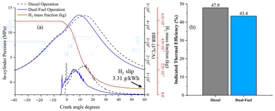
Figure 4.
(a) In-cylinder pressure, heat release rate, and hydrogen mass fraction and (b) indicated thermal efficiency for the diesel and dual-fuel operations.
Figure 5a reports the NOx emissions, in-cylinder temperature, and combustion duration for the diesel and dual-fuel operations. Combustion during DF operation commences earlier due to increased in-cylinder temperature that raises the reactivity. The combustion duration is measured in terms of CA10 and CA90 and is presented as slightly reduced in the case of the DF operation due to faster combustion of hydrogen. Also, the fact that 7.6% of hydrogen remains unburned contributes to shorter combustion duration as well. The increased temperature at the IVC point yields increased peak in-cylinder temperature penalising NOx emissions. Formation of NO and NO2 is linked to the cylinder temperature and residence time of high-temperature combustion products. During the premixed combustion phase, the rapid heat release favours NO formation as local temperature exceeds the 1800 K cut-off. NO temporal distribution follows that of temperature, peaking close to 30 °CA TDC close to maximum cylinder temperature. Conversely, NO2 is influenced by the post-flame temperature and oxygen availability. The NO oxidation reaction to NO2 is exothermic, and is favoured as temperature reduces. During DF combustion, the existence of HO2 radicals is expected to catalyse more NO to NO2 (NO + HO2 → NO2 + OH). Figure 5b presents the NOx emissions per energy output of the engine, where it is evident that during dual fuel operation with 60% hydrogen the NOx emissions yield 10.03 g/kWh, as opposed to only diesel operation, which resulted in 6.46 g/kWh.
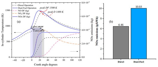
Figure 5.
(a) In-cylinder temperature and NOx formation and (b) specific NOx emissions for the diesel and dual-fuel operation.
Figure 6 depicts the in-cylinder temperature and the mass fraction distribution of hydrogen and diesel in dual-fuel operation. Hydrogen is fully homogenous in-cylinder by the start of injection of diesel. At 0.5 °CA BTDC, 10% of combustion has occurred, with the premixed combustion of hydrogen and diffusive combustion of diesel. The temperature at this point has increased moderately with hot spots being noticed at the injector nozzle. Hydrogen combustion occurs at two different points in-cylinder, with one being close to diesel jet and the other close to the piston wall where premixed hydrogen contacts the fame front of the diesel. As combustion propagates at 8 °CA ATDC, the increase in temperature is attributed to hydrogen combustion from the existing flame front of diesel fuel, being concentrated at the bottom of the piston bowl. At 24 °CA ATDC, during the expansion phase, it is evident that an amount of hydrogen close to the cylinder wall and head is still unburned. At this point, temperature is more uniform in-cylinder and the flame is concentrated at the piston bowl. Such behavior indicates that the burning process will yield incomplete hydrogen combustion by the end of the closed cycle.
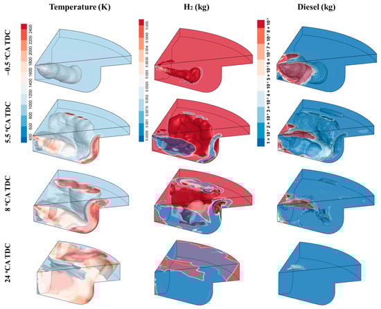
Figure 6.
In-cylinder temperature, hydrogen, and diesel mass fraction for the DF operation.
Figure 7 indicates the in-cylinder species at temperatures exceeding 2700 K for diesel and dual-fuel operation. Since NOx formation follows an exponential relationship with temperature, the extent and distribution of high-temperature regions directly correlate with emissions. The high NOx emissions yielded from dual-fuel hydrogen operation are explained by the increased residence time of in-cylinder species at temperature above 2700 K. The difference between diesel and DF cases pertains to the higher cylinder temperature reached during hydrogen combustion. The peak mass fraction for diesel operation is 0.0025%, whereas for the dual-fuel it is 0.025%, hence a greater mass of mixture is exposed at high temperature and for greater time favouring the oxidation of atmospheric nitrogen to NO and NO2.
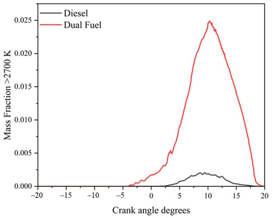
Figure 7.
In-cylinder species at temperature greater than 2700 K for diesel and DF operation.
Figure 8 illustrates the contours of OH radicals and HO2 for dual-fuel operation, providing key insights into flame propagation and ignition of the in-cylinder mixture. OH radicals indicate combustion intensity and are concentrated in the reaction zones of premixed flames, making them useful for identifying flame front structures. At 0.5 °CA BTDC, small concentrations of them are noticed at the perimeter of the diesel jet. As combustion propagates at 8 °CA ATDC and hydrogen is consumed, OH is concentrated at the top of the cylinder close to the head, with sporadic high concentration spots. This is the point of peak heat release rate; however, no clear regions in-cylinder are noticed with a high concentration of OH radicals. Such behavior indicates that dual-fuel operation with hydrogen and the determined initial conditions yields stable combustion.
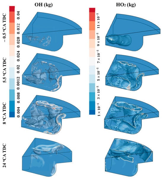
Figure 8.
Contours of OH and HO2 for the DF operation.
Hydroperoxil (HO2) is a secondary species formed under fuel-lean or low-to-intermediate temperature conditions during hydrogen oxidation to H2O, and acts as a precursor to more reactive species such as OH (HO2 + H → 2OH) [26]. Increased concentrations of it in low-temperature regions indicate enhanced chain termination impeding oxidation and yielding incomplete combustion. According to the contours presented, at 8 °CA ATDC, HO2 is located at the bottom of the piston bowl, and high concentration regions are presented at the cylinder head and close to the wall. At 24 °CA ATDC, where 90% of the fuel is burned, HO2 is concentrated close to the cylinder wall, in the same region where unburned hydrogen is spotted, yielding potential combustion termination.
4. Discussion
The results of this study demonstrate that operating a large-bore marine diesel engine in dual-fuel mode with a high hydrogen energy fraction (60%) leads to distinct combustion and emission characteristics that both confirm and extend previous findings in the literature as presented by the pertinent studies of Karvounis et al. [20], Malloupas et al. [34], and Dere [35]. The earlier start of combustion and higher in-cylinder peak temperatures observed in the present work corroborate the hypothesis that hydrogen enrichment accelerates ignition, but at the expense of significantly elevated NOx emissions due to prolonged residence time in high-temperature regions. The presence of unburned hydrogen near the cylinder walls, together with high HO2 concentrations, further supports the notion that incomplete oxidation and radical chain termination can constrain the full exploitation of hydrogen reactivity, even under elevated intake temperature. Importantly, the advanced in-cylinder analysis conducted highlights not only the enhanced formation of NO and NO2 but also the spatial dynamics of OH and HO2 radicals, thereby offering a comprehensive understanding of flame propagation and stability. These insights validate the working hypothesis that high hydrogen fractions in marine dual-fuel engines present a complex trade-off between efficiency and emissions, reinforcing the urgent need for targeted mitigation strategies such as exhaust gas recirculation, optimised injection timing, or aftertreatment solutions. While the qualitative trends observed for high load operation, such as accelerated ignition, elevated peak temperatures, and enhanced NOx formation, are expected to persist at lower loads, the magnitude of these effects is expected to vary with engine operating conditions. At medium loads, reduced in-cylinder temperatures and shorter residence times could moderate NOx formation, whereas higher hydrogen fractions could further accelerate combustion and exacerbate radical-driven processes. Varying the hydrogen energy fraction at the same load requires modifications in the intake conditions to sustain complete combustion without knocking phenomena, as proposed in authors previous study [30]. In a broader context, the findings contribute to the maritime sector’s decarbonization agenda by quantifying the potential and challenges of retrofitting existing diesel engines for hydrogen use, thereby complementing the IMO’s greenhouse gas reduction targets. Future research should focus on the parametric optimisation of injection strategies, the integration of advanced aftertreatment technologies, and the coupling of CFD simulations with full-scale experimental validation under realistic marine duty cycles to ensure both technical feasibility and regulatory compliance. In this way, the current study provides a critical foundation for advancing hydrogen-based propulsion solutions while identifying the pathways required to balance environmental performance with operational reliability.
5. Conclusions
This study investigated the dual-fuel operation of a medium-speed marine diesel engine with 60% hydrogen energy fraction. The associated emissions were analyzed by CFD means and a comparative assessment with diesel operation was performed.
The main findings are summarized as follows:
- ▪
- Combustion starts earlier in dual-fuel operation, leading to an advanced in-cylinder peak pressure. However, a small portion of hydrogen remains unburned due to in-cylinder reactivity limitations.
- ▪
- The dual-fuel mode experiences higher in-cylinder peak temperature and a greater mass fraction in the high temperature (over 2700 K) region, favoring NOx generation.
- ▪
- Unburned hydrogen remains near the cylinder wall at the low temperature region in-cylinder where the high concentration of HO2 indicates combustion inhibition.
Overall, the study highlights the potential of hydrogen dual-fuel engines for marine applications. Furthermore, it sheds light on the in-cylinder behavior of combustion and emissions. Such findings are expected to be used for the development of emissions reduction strategies in dual-fuel hydrogen engines.
The study is limited to high load operation of the marine engine, as high in-cylinder reactivity yields more severe combustion conditions. Validation of dual-fuel combustion with a small-bore engine inhibits inherent uncertainty with regards to extendibility of the results for large-bore marine engines. In the current analysis, the same CFD models are used for both small- and large-bore engines, ensuring in-cylinder behavior of the mixture (turbulence intensity, DamKöhler and Peclet number) is comparable. A comprehensive analysis through the engine operating envelope is expected as a follow up study. Furthermore, the developed CFD model assumes a fully premixed hydrogen–air charge, which may not capture stratification and local quenching effects present in real engines.
Author Contributions
Conceptualization, P.K. and G.T.; Methodology, P.K. and G.T.; Software, P.K.; Validation, B.G.; Formal analysis, P.K. and B.G.; Investigation, P.K. and G.T.; Resources, G.T. and B.G.; Data curation, B.G. and P.Z.; Writing—original draft, P.K.; Writing—review and editing, G.T.; Visualization, P.K.; Supervision, G.T. and P.Z.; Project administration, G.T.; Funding acquisition, G.T. All authors have read and agreed to the published version of the manuscript.
Funding
This research was funded by Maritime Research & Innovation UK (MarRi—UK) research project: AI-Driven Hydrogen Safety and Operational Intelligence for Marine Engines (HySOME).
Data Availability Statement
The original contributions presented in this study are included in the article. Further inquiries can be directed to the corresponding author.
Acknowledgments
The authors greatly acknowledge the funding from DNV AS and RCCL for the MSRC establishment and operation. The opinions expressed herein are those of the authors and should not be construed to reflect the views of DNV AS and RCCL. We would like to thank Convergent Science for offering their software (CONVERGE) and their technical support for the accomplishment of this research.
Conflicts of Interest
The authors declare no conflicts of interest.
Appendix A
Figure A1 represents the NOx emissions modelling in the dual-fuel case that includes 60% hydrogen energy fraction, exploring the effect of prompt NOx creation on overall NOx formation. Prompt NOx is usually a small fraction (below 5%) of the thermal NOx in dual-fuel engines. According to the Fenimore mechanism for the prompt NOx formation, hydrogen contains no carbon-to-carbon bonds, as a carbon-free fuel, and hence produce few CH radicals that act as key precursors for prompt NOx [36]. From the analysis their contribution to overall NOx emissions is close to 4.34%. Concurrently, the CFD convergency duration has increased by six times. To that end, the authors decided to exclude prompt NOx from the developed model.

Figure A1.
Evaluating the effect of prompt NOx emissions contribution to overall NOx creation in dual-fuel hydrogen combustion.
The developed CFD model was applied to simulate the closed-cycle operation of the studied marine engine in natural gas mode. The engine functions on the principle of premixed combustion, wherein natural gas is injected into the cylinder port and is considered fully premixed with air, while a small amount of pilot diesel is directly injected into the cylinders to trigger natural gas ignition. Experimental data were obtained during the engine shop test trials. Table A1 presents both the simulated and measured values of indicated power, peak in-cylinder pressure, and NOx emissions across four load conditions (25%, 50%, 75%, and 100%).
Table A1.
Calculated and experimental (from shop test trials) indicated power, maximum in-cylinder pressure, and NOx emissions for the considered marine engine operation in the natural gas mode.
Table A1.
Calculated and experimental (from shop test trials) indicated power, maximum in-cylinder pressure, and NOx emissions for the considered marine engine operation in the natural gas mode.
| Load (%) | Indicated Power Output | Maximum In-Cylinder Pressure | Indicated NOx Emissions | ||||||
|---|---|---|---|---|---|---|---|---|---|
| Measured (kW) | CFD (kW) | E (%) | Measured (bar) | CFD (bar) | E (%) | Measured (g/kWh) | CFD (g/kWh) | E (%) | |
| 25 | 1950 | 1900 | 3.6 | 38 | 38 | 0 | 9.15 | 9.9 | 8.6 |
| 50 | 3900 | 3950 | 2.3 | 64 | 66 | 4.1 | 9.7 | 10.1 | 4 |
| 75 | 5850 | 5700 | 3.6 | 92 | 90 | 3.2 | 9.7 | 10.4 | 7.8 |
| 100 | 7800 | 7890 | 2.2 | 126 | 125 | 1.8 | 9.43 | 10 | 6.7 |
References
- Karvounis, P.; Theotokatos, G.; Boulougouris, E. Environmental-economic sustainability of hydrogen and ammonia fuels for short sea shipping operations. Int. J. Hydrogen Energy 2024, 57, 1070–1080. [Google Scholar] [CrossRef]
- Stępień, Z. A comprehensive overview of hydrogen-fueled internal combustion engines: Achievements and future challenges. Energies 2021, 14, 6504. [Google Scholar] [CrossRef]
- Onorati, A.; Payri, R.; Vaglieco, B.M.; Agarwal, A.K.; Bae, C.; Bruneaux, G.; Canakci, M.; Gavaises, M.; Günthner, M.; Hasse, C.; et al. The role of hydrogen for future internal combustion engines. Int. J. Engine Res. 2022, 23, 529–540. [Google Scholar] [CrossRef]
- Shadidi, B.; Najafi, G.; Yusaf, T. A review of hydrogen as a fuel in internal combustion engines. Energies 2021, 14, 6209. [Google Scholar] [CrossRef]
- Dimitriou, P.; Tsujimura, T. A review of hydrogen as a compression ignition engine fuel. Int. J. Hydrogen Energy 2017, 42, 24470–24486. [Google Scholar] [CrossRef]
- Kumar, M.; Bhowmik, S.; Paul, A. Effect of pilot fuel injection pressure and injection timing on combustion, performance and emission of hydrogen–biodiesel dual fuel engine. Int. J. Hydrogen Energy 2022, 47, 29554–29567. [Google Scholar] [CrossRef]
- Huang, Z.; Yuan, S.; Wei, H.; Zhong, L.; Hu, Z.; Liu, Z.; Liu, C.; Wei, H.; Zhou, L. Effects of hydrogen injection timing and injection pressure on mixture formation and combustion characteristics of a hydrogen direct injection engine. Fuel 2024, 363, 130966. [Google Scholar] [CrossRef]
- Rueda-Vázquez, J.M.; Serrano, J.; Jiménez-Espadafor, F.J.; Dorado, M.D. Experimental analysis of the effect of hydrogen as the main fuel on the performance and emissions of a modified compression ignition engine with water injection and compression ratio reduction. Appl. Therm. Eng. 2024, 238, 121933. [Google Scholar] [CrossRef]
- Khalid, A.H.; Said, M.F.; Veza, I.; Abas, M.A.; Roslan, M.F.; Abubakar, S.; Jalal, M.R. Hydrogen port fuel injection: Review of fuel injection control strategies to mitigate backfire in internal combustion engine fuelled with hydrogen. Int. J. Hydrogen Energy 2024, 66, 571–581. [Google Scholar] [CrossRef]
- Zhou, L.; Cheung, C.S.; Leung, C.W.; Huang, Z. Combustion, performance and emissions of a diesel engine with H2, CH4 and H2-CH4 addition. Int. J. Hydrogen Energy 2014, 39, 4611–4621. [Google Scholar] [CrossRef]
- Li, Z.; Liu, J.; Ji, Q.; Sun, P.; Wang, X.; Xiang, P. Influence of hydrogen fraction and injection timing on in-cylinder combustion and emission characteristics of hydrogen-diesel dual-fuel engine. Fuel Process. Technol. 2023, 252, 107990. [Google Scholar] [CrossRef]
- Köse, H.; Ciniviz, M. An experimental investigation of effect on diesel engine performance and exhaust emissions of addition at dual fuel mode of hydrogen. Fuel Process. Technol. 2013, 114, 26–34. [Google Scholar] [CrossRef]
- Talibi, M.; Hellier, P.; Balachandran, R.; Ladommatos, N. Effect of hydrogen–diesel fuel co-combustion on exhaust emissions with verification using an in-cylinder gas sampling technique. Int. J. Hydrogen Energy 2014, 39, 15088–15102. [Google Scholar] [CrossRef]
- Manzoor, M.U.; Yosri, M.; Talei, M.; Poursadegh, F.; Yang, Y.; Brear, M. Normal and knocking combustion of hydrogen: A numerical study. Fuel 2023, 344, 128093. [Google Scholar] [CrossRef]
- Verhelst, S.; Sierens, R. Aspects concerning the optimisation of a hydrogen fueled engine. Int. J. Hydrogen Energy 2001, 26, 981–985. [Google Scholar] [CrossRef]
- Farzam, R.; McTaggart-Cowan, G. Hydrogen–diesel dual-fuel combustion sensitivity to fuel injection parameters in a multi-cylinder compression-ignition engine. Int. J. Hydrogen Energy 2024, 49, 850–867. [Google Scholar] [CrossRef]
- Smallbone, A.; Bhave, A.; Kraft, M. Virtual Performance and Emissions Mapping for Diesel Engine Design Optimization; 2011-01-1441; SAE Technical Paper; SAE: Warrendale, PA, USA, 2011. [Google Scholar]
- Li, Y.; Gao, W.; Zhang, P.; Fu, Z.; Cao, X. Influence of the equivalence ratio on the knock and performance of a hydrogen direct injection internal combustion engine under different compression ratios. Int. J. Hydrogen Energy 2021, 46, 11982–11993. [Google Scholar] [CrossRef]
- Babayev, R.; Andersson, A.; Dalmau, A.S.; Im, H.G.; Johansson, B. Computational comparison of the conventional diesel and hydrogen direct-injection compression-ignition combustion engines. Fuel 2022, 307, 121909. [Google Scholar] [CrossRef]
- Karvounis, P.; Theotokatos, G.; Gu, B.; Zhou, P. Numerical investigation of premixed hydrogen combustion in dual-fuel marine engines at high load. Int. J. Hydrogen Energy 2025, 144, 239–251. [Google Scholar] [CrossRef]
- Sharma, P.; Dhar, A. Compression ratio influence on combustion and emissions characteristic of hydrogen diesel dual fuel CI engine: Numerical Study. Fuel 2018, 222, 852–858. [Google Scholar] [CrossRef]
- Karvounis, P.; Theotokatos, G. Parametric optimisation of diesel–methanol injection timings of a dual-fuel marine engine operating with high methanol fraction using CFD. Appl. Therm. Eng. 2025, 264, 125433. [Google Scholar] [CrossRef]
- Karvounis, P.; Theotokatos, G.; Patil, C.; Xiang, L.; Ding, Y. Parametric investigation of diesel–methanol dual fuel marine engines with port and direct injection. Fuel 2025, 381, 133441. [Google Scholar] [CrossRef]
- Karvounis, P.; Theotokatos, G. Performance improvement and emissions reduction of methanol fuelled marine dual-fuel engine with variable compression ratio. Fuel Process. Technol. 2025, 272, 108208. [Google Scholar] [CrossRef]
- Werner, H.; Wengle, H.J. Large-eddy simulation of turbulent flow over and around a cube in a plate channel. In Turbulent Shear Flows 8: Selected Papers from the Eighth International Symposium on Turbulent Shear Flows, Munich, Germany, 9–11 September 1991; Springer: Berlin/Heidelberg, Germany, 1993; pp. 155–168. [Google Scholar]
- Ricart, L.M.; Reitz, R.D.; Dec, J.E. Comparisons of diesel spray liquid penetration and vapor fuel distributions with in-cylinder optical measurements. J. Eng. Gas Turbines Power 2000, 122, 588–595. [Google Scholar] [CrossRef]
- Zeldovich, Y.B. The Oxidation of Nitrogen in Combustion Explosions. J. Acta Physicochim. 1946, 21, 577–628. [Google Scholar]
- Schmidt, D.P.; Rutland, C.J. A New Droplet Collision Algorithm. J. Comput. Phys. 2000, 164, 62–80. [Google Scholar] [CrossRef]
- Han, Z.Y.; Xu, Z.; Trigui, N. Spray/wall interaction models for multidimensional engine simulation. Int. J. Eng. Res. 2000, 1, 127–146. [Google Scholar] [CrossRef]
- Yang, X.; Gupta, S.; Kuo, T.W.; Gopalakrishnan, V. RANS and large eddy simulation of internal combustion engine flows—A comparative study. J. Eng. Gas Turbines Power 2014, 136, 051507. [Google Scholar] [CrossRef]
- Tsitsilonis, K.M.; Theotokatos, G. A novel method for in-cylinder pressure prediction using the engine instantaneous crankshaft torque. Proc. Inst. Mech. Eng. Part M J. Eng. Marit. Environ. 2022, 236, 131–149. [Google Scholar] [CrossRef]
- Tsujimura, T.; Suzuki, Y. The utilization of hydrogen in hydrogen/diesel dual fuel engine. Int. J. Hydrogen Energy 2017, 42, 14019–14029. [Google Scholar] [CrossRef]
- Andrae, J.C.; Head, R.A. HCCI experiments with gasoline surrogate fuels modeled by a semidetailed chemical kinetic model. Combust. Flame 2009, 156, 842–851. [Google Scholar] [CrossRef]
- Mallouppas, G.; Yfantis, E.A.; Frantzis, C.; Zannis, T.; Savva, P.G. The effect of hydrogen addition on the pollutant emissions of a marine internal combustion engine genset. Energies 2022, 15, 7206. [Google Scholar] [CrossRef]
- Dere, C. Hydrogen fueled engine technology, adaptation, and application for marine engines. In Decarbonization of Maritime Transport; Springer Nature: Singapore, 2023; pp. 45–63. [Google Scholar]
- Fenimore, C.P. Formation of nitric oxide in premixed hydrocarbon flames. In Symposium (International) on Combustion; Elsevier: Amsterdam, The Netherlands, 1971; Volume 13, pp. 373–380. [Google Scholar]
Disclaimer/Publisher’s Note: The statements, opinions and data contained in all publications are solely those of the individual author(s) and contributor(s) and not of MDPI and/or the editor(s). MDPI and/or the editor(s) disclaim responsibility for any injury to people or property resulting from any ideas, methods, instructions or products referred to in the content. |
© 2025 by the authors. Licensee MDPI, Basel, Switzerland. This article is an open access article distributed under the terms and conditions of the Creative Commons Attribution (CC BY) license (https://creativecommons.org/licenses/by/4.0/).