1. Introduction
The maritime industry is responsible for the emission of about one billion tons of carbon dioxide (CO
2) and about 2.5% of global greenhouse gas (GHG) emissions worldwide [
1,
2]. For over a century, the main propulsive systems on board ocean-going vessels were marine diesel engines fueled with heavy diesel oil. Historically, marine propulsion evolved from coal-fired steam engines to oil-based internal combustion engines, with HFO and MDO becoming dominant throughout the twentieth century. At present, the global fleet remains overwhelmingly dependent on fossil fuels, with more than 80% of ships operating on HFO or MDO, around 5–6% using LNG, and only a marginal share currently adopting alternative fuels such as methanol, biofuels, or hydrogen [
3]. The use of this fossil fuel involved the ever-increasing emissions of GHG and air pollutants above all in port areas [
4], such as carbon dioxide (CO
2), nitrogen oxides (NO
x), sulfur oxides (SO
x), and particulate matter (PM). The drastic reduction in GHG emissions from ships is set as one of the urgent targets to achieve the EU Green Deal objectives [
4]. As a matter of fact, the International Maritime Organization (IMO) has underlined the need to reduce CO
2 emissions from shipping by at least 50% by the year 2050 in comparison to the emission levels in 2008 [
5,
6]. To comply with these goals, the introduction of alternative solutions/technology capable of making shipping more climate friendly, and at the same time ensuring the current performance levels, is needed.
Currently, the technological state of the art for both fuels and propulsion systems is not enough to meet the global and EU’s target emission levels [
7]. As a matter of fact, it is necessary to analyze and evaluate game-changing technologies, properly assessing their environmental, social, and economic impacts, which can contribute to the EU’s and sector’s goals [
8].
The introduction of zero-emission fuels as hydrogen (H
2) and hydrogen carriers, together with the implementation of innovative propulsion technologies such as fuel cells, can pave the way to meet the climate-neutral goal in shipping [
9,
10,
11]. As hydrogen carriers, ammonia (NH
3), and methanol (CH
3OH) are considered very promising candidates as fuels, thanks to easier storage feasibility (they are stored as liquid fuels) and also for their high volumetric energy densities (11.5 MJ/L and 15.8 MJ/L for liquid ammonia and methanol, respectively). However, the adoption of these fuels also raises specific safety and compatibility challenges. Ammonia is highly toxic and corrosive, requiring dedicated containment, double-walled tanks, and ventilation systems, which may reduce the effective usable volume [
12,
13]. Liquid hydrogen has a very low boiling point (−253 °C), which demands cryogenic tanks, insulation, and the management of boil-off losses [
14]. Methanol, while more easily stored in conventional tanks, has a low flash point (~11 °C) and is regulated under the IGF Code for low-flashpoint fuels, requiring appropriate fire safety and handling systems [
15,
16]. These aspects highlight that, in addition to mass and volume constraints, regulatory and safety requirements significantly affect the effective integration of each fuel.
In addition to compatibility aspects, safety considerations represent the primary prerequisite for the adoption of alternative fuels in maritime applications. Ammonia, due to its toxicity and corrosiveness, requires double-walled containment, continuous leakage detection, and dedicated ventilation systems, which inevitably influence tank design and the effective usable volume. Liquid hydrogen is characterized by high flammability, potential explosive mixtures, and boil-off losses, thus demanding cryogenic tanks, advanced insulation, controlled venting strategies, and strict compliance with the IGF Code. These protective measures, as already discussed in the literature [
15,
16], are essential to ensure safe storage and operation on board and must always be considered alongside thermodynamic performance and volumetric feasibility in the evaluation of multi-fuel SOFC systems.
As innovative propulsion technologies for long-distance deep-sea shipping, Solid Oxid Fuel Cells (SOFCs) are the most attractive option, thanks to their high efficiency, good power capacity, and high sensitivity to fuel/oxidant impurities [
17,
18,
19]. These considerations lay the foundation for analyzing SOFC-based ship propulsion systems designed to run on ammonia and methanol from a technical, energetic, environmental, and economic point of view.
It is in this context that this work is placed as it illustrates the preliminary results of both a performance analysis of an innovative SOFC-based powertrain designed to run on multiple fuels and a feasibility assessment for the installation of different fuel tanks.
1.1. Review on SOFC-Based Propulsion System Fed with Ammonia and Methanol
The feasibility of SOFC technology employment in shipping is widely explored in scientific literature, with a particular focus on alternative fuels and the associated challenges.
Barelli et al. (2020) [
20] studied ammonia-fed SOFC systems by fitting the experimental results of a six-cell SOFC stack over a 100 kW model in their analysis. Their findings indicated that ammonia is a promising fuel for SOFCs, offering stable and efficient performance. Electrical system efficiency reaches up to 52% in nominal conditions, while the NH
3 flow rate is 10.29 g/s with NO
x emissions in the range of 40–250 ppm at the highest current densities. As reported in ref. [
20], these values refer to laboratory-scale SOFC tests and cannot be directly compared with current IMO marine emission standards. Hence, NH
3-fed SOFC systems could represent a sustainable solution in energy generation, seeing that authors also assessed the Levelized Cost of Energy around 0.221
$/kWh to give a comprehensive indication for SOFC power systems’ design and modeling.
Cinti et al. (2016) [
12] also investigated ammonia-fed SOFCs, focusing on stack testing and system analysis, confirming the stable operation of ammonia-powered SOFCs. The study focused on a thermodynamic model based on a four-cell short stack SOFC system, with a total active area of 320 cm
2 and an operating temperature of 700 °C. By considering different inlet gas compositions and varying the stack polarization curve, the authors evaluated the working stability of the system. The analysis highlighted that working with diluted ammonia guaranteed system efficiency up to 50% with the advantage of operating with non-toxic, non-flammable, and easy-to-handle substance, suggesting its potential applications in the field of power units with high efficiency and zero emissions.
Hagen et al. (2019) [
21] explored the use of various hydrogen carriers, as biogas and ammonia, for powering SOFCs’ experimental setups with an active area of 16 cm
2. The analysis demonstrated the stable operation of the system (1500 h) at a lab scale size with a power output of about 0.70 W/cm
2 and electrical efficiencies that reach up to 40%, using NH
3. Moreover, the absence of carbonous emissions coupled with the previously listed advantages and an established widespread availability of the fuel support the potential for SOFC power systems.
On the other hand, Duong et al. (2022) [
22] proposed a novel maritime propulsion system based on SOFCs powered by methanol, integrated with Proton Exchange Membrane Fuel Cells (PEMFCs) and Combined Heat and Power (CHP) production. The proposed system was designed for a 3.80 MW cargo vessel fueled by CH
3OH. After the integration with PEMFC and CHP systems, the output power reached up to 5.65 MW. Authors concluded that the SOFC-based propulsion systems using methanol as a fuel can be promising, and in order to thoroughly comprehend the applicability of the presented system, further research on the economic and sustainability aspects should be carried out.
Cocco et al. [
23] investigated hybrid systems combining SOFCs and micro gas turbines, fueled by methanol and dimethyl ether (DME). When fed by CH
3OH at an operating temperature of 900 °C, the system achieved a maximum hybrid plant efficiency and SOFC efficiency of about 67.8% and 50%, respectively. These efficiencies are net values from the system model, as they include the external reformer and heat exchanger integration, whereas minor parasitic loads were not explicitly accounted for in the original study [
18]. The article also investigated fuel reforming, showing that the optimal reforming temperature for methanol is about 240 °C, considering the same SOFC operating temperature. This assessment was a preliminary step toward SOFC-based propulsive systems; in particular, its adaptability to various operating conditions further suggests its potential for distributed applications, offering a high-efficiency solution for maritime propulsion.
Van Veldhuizen et al. [
24] analyzed SOFC-based propulsive systems fed with different alternative fuels and based on different criteria, going from production capacity and availability to technology readiness and fuel cost, without neglecting factors operating and investment costs as well as emissions. The results showed five different alternative fuels compatible with SOFC operations: liquified natural gas (LNG), Methanol, Fischer–Tropsch diesel, ammonia, and hydrogen. While in another work [
20], they focused on the technical and economic feasibility of SOFC systems in hybrid propulsion applications for the maritime sector, highlighting the efficiency and environmental benefits of SOFCs over traditional propulsion systems since the volumetric energy density could vary between 1.00 and 25.00 kW/m
3 and system efficiencies could reach up to 65%. Moreover, their study suggested that hybrid strategies, transient capabilities, heat supply matching, and the impact of marine operating conditions on SOFC performance are key aspects to be investigated.
In addition, recent studies on advanced carbon-based and MOF-derived materials have further explored surface reaction mechanisms and pollutant removal processes, providing complementary insights into catalytic pathways under redox environments [
25]. Despite the promising achievements reported in the above studies, several controversies and open challenges remain in the research on SOFC systems for maritime applications. First, the complexity of fuel reforming and cracking processes is still debated, especially with regard to efficiency penalties, catalyst durability, and system controllability under varying loads. Second, carbon deposition and accelerated degradation represent critical issues when operating with carbon-based fuels such as methanol, and the literature shows divergent conclusions on the long-term impact of these phenomena. Third, there is a clear trade-off between volumetric energy density and the limited storage space available on board, which strongly affects the feasibility of large-scale integration. Finally, safety aspects related to toxicity, flammability, and the compliance of storage solutions with international regulations (e.g., IGF Code) remain a major barrier to widespread adoption.
In addition to these open issues, it is worth noting that most of the existing research has been limited to single-fuel SOFC configurations, while systematic analyses of multi-fuel operations in the maritime sector are still scarce. The potential of a multi-fuel approach is often mentioned as a desirable feature to enhance the flexibility and resilience of future shipping energy systems, but quantitative assessments remain very limited.
1.2. Research Purpose and Original Contributions
Building on the gaps and controversies identified in the literature, the present study aims to advance the understanding of multi-fuel SOFC systems for maritime propulsion. While previous research has mainly investigated single-fuel SOFC configurations and has been largely limited to thermodynamic modeling, the novelty of this work lies in adopting a systematic multi-fuel perspective, simultaneously considering ammonia, liquid hydrogen, and methanol within the same framework.
In doing so, the study goes beyond a purely performance-oriented approach and incorporates feasibility aspects related to fuel storage, mass and volume requirements, and integration on board a container ship. A short discussion on safety and regulatory prerequisites is also included to complement the analysis and underline that toxicity, cryogenic conditions, and flashpoint regulations represent essential boundary conditions for any practical adoption. Above all, the analysis explicitly addresses bunkering flexibility, highlighting how the possibility to switch between different fuels represents the key innovation of the multi-fuel SOFC approach and one of the main contributions of this work.
This novel approach fits into the framework of the European project FuelSOME. The vision of the project is to find a scalable and flexible way to supply multiple fuels, i.e., ammonia and methanol in addition to hydrogen, to act as major contenders to replace marine diesel as a fuel for ocean-going vessels coupled with their use in a multi-fuel power generation system based on SOFC technology. The flexibility provided by multi-fuel feeding makes it possible to overcome the limits related to the availability of these fuels in various ports. The innovative concept proposed in FuelSOME is demonstrated through the design and development of a single power system, SOFC and its Balance of Plant (BoP), capable of being supplied and powered by multiple fuels, including ammonia, methanol, and hydrogen.
This paper focuses on the numerical assessment of a multi-fuel system, first by evaluating the performance of a small-scale (3 kW) configuration using a properly developed numerical model, and then by studying the same concept scaled to a multi-megawatt SOFC powertrain, analyzing its thermodynamic behavior and installation feasibility for application on an ocean-going vessel. The multi-fuel system is conceived as a system that is able to operate separately with different fuels, like ammonia, methanol, or hydrogen.
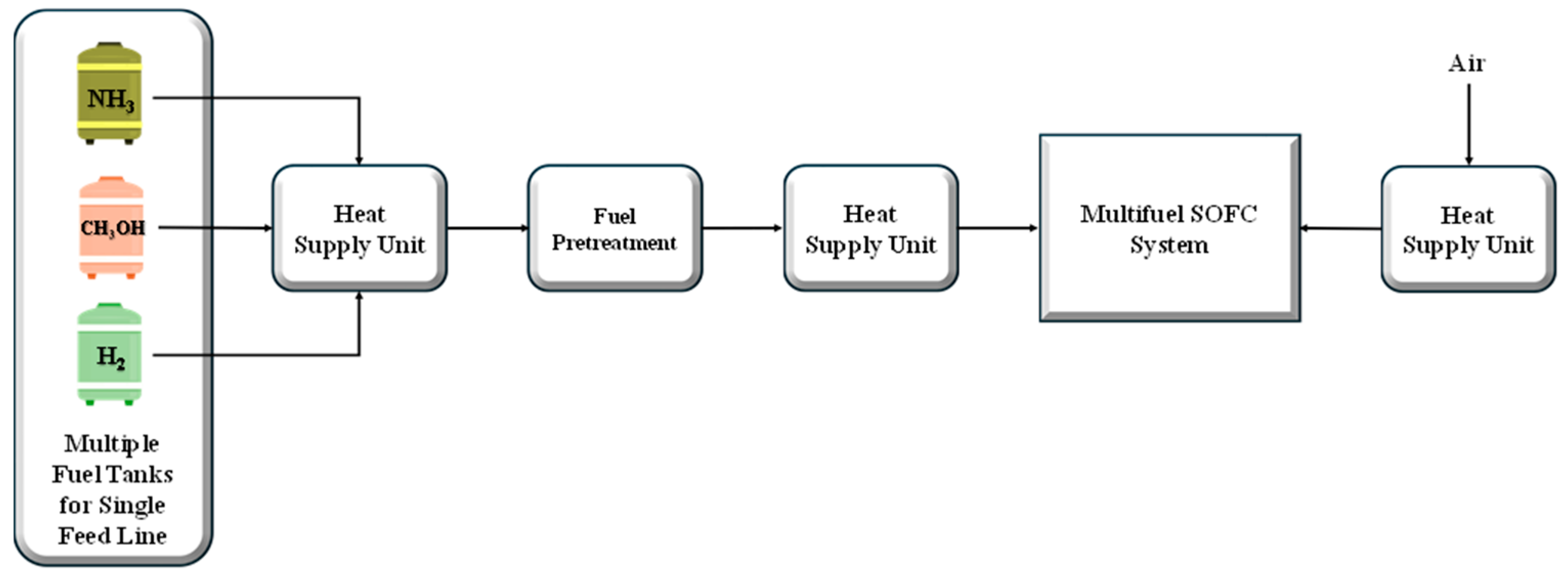
Figure 1 shows the well-structured methodological approach developed for the analysis.
Firstly, the small-scale SOFC power system is presented and described. Then, the system modeling and its performance results are illustrated, followed by the analysis of the scaling up of the proposed system to multi-megawatt application. Finally, different bunkering solutions are analyzed for evaluating the feasibility of multi-fuel system installation on board ships. In the feasibility analysis, the evaluation of the mass and volume of the SOFC propulsion system is neglected.
In summary, the originality of this work lies in demonstrating, for the first time, the feasibility of a multi-fuel SOFC propulsion system that combines thermodynamic performance with storage and installation constraints, while emphasizing bunkering flexibility as a key innovation boundary compared with existing single-fuel studies.
3. Results
This section reports the main findings of the study. First, the outcomes of the thermo-electrochemical model are presented, including system efficiencies and flow compositions under nominal operating conditions. Then, the feasibility analysis for the installation of different fuel storage solutions on board is discussed, highlighting the implications in terms of weight and volume compared to conventional diesel systems.
3.1. Modeling Results
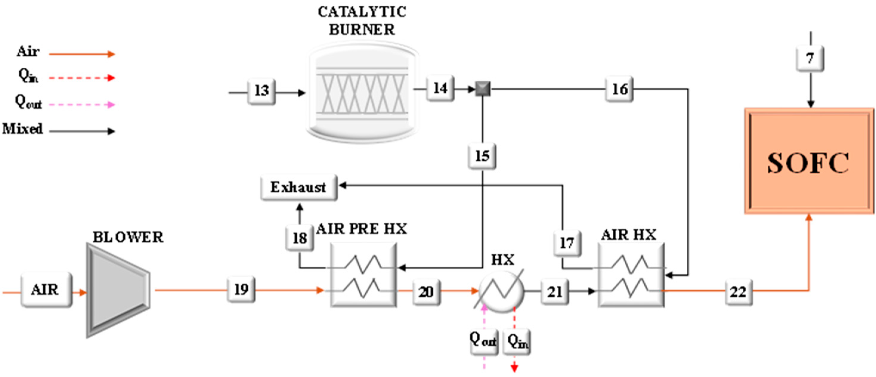
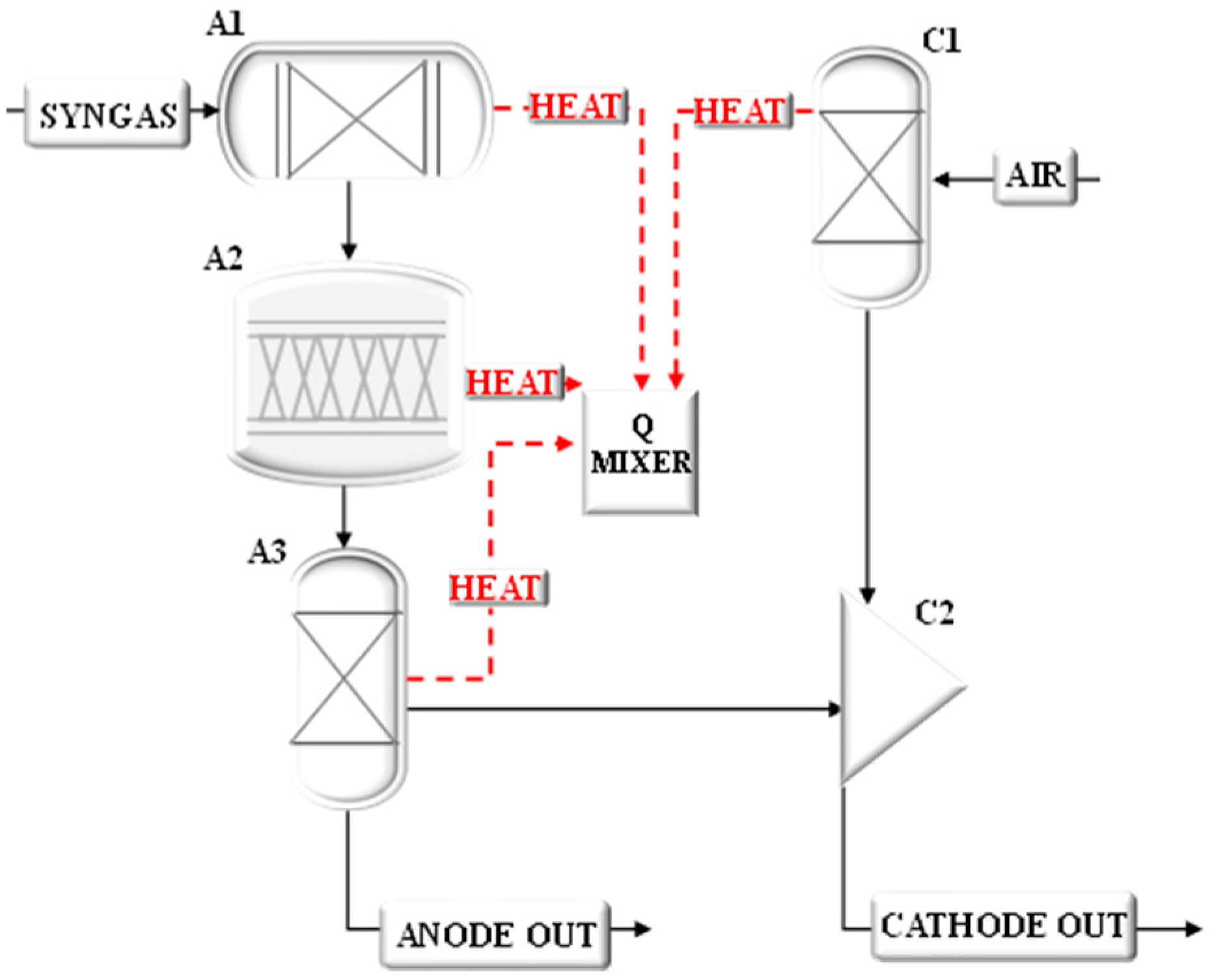
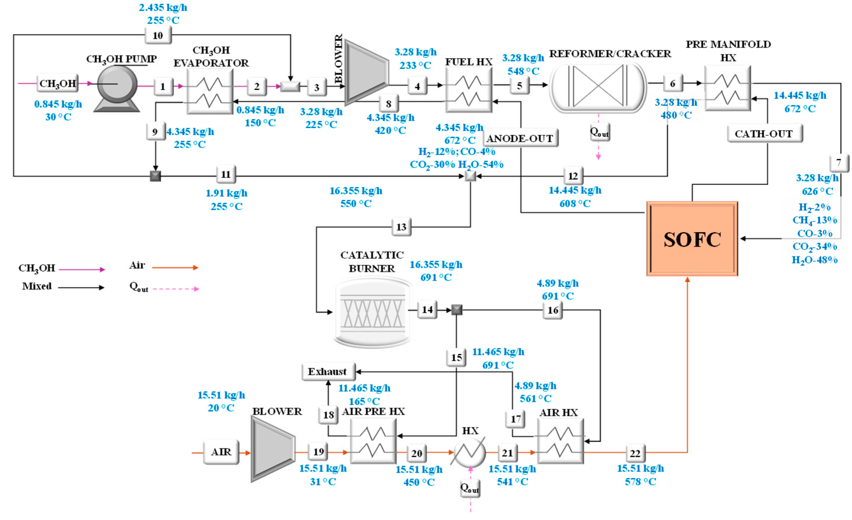
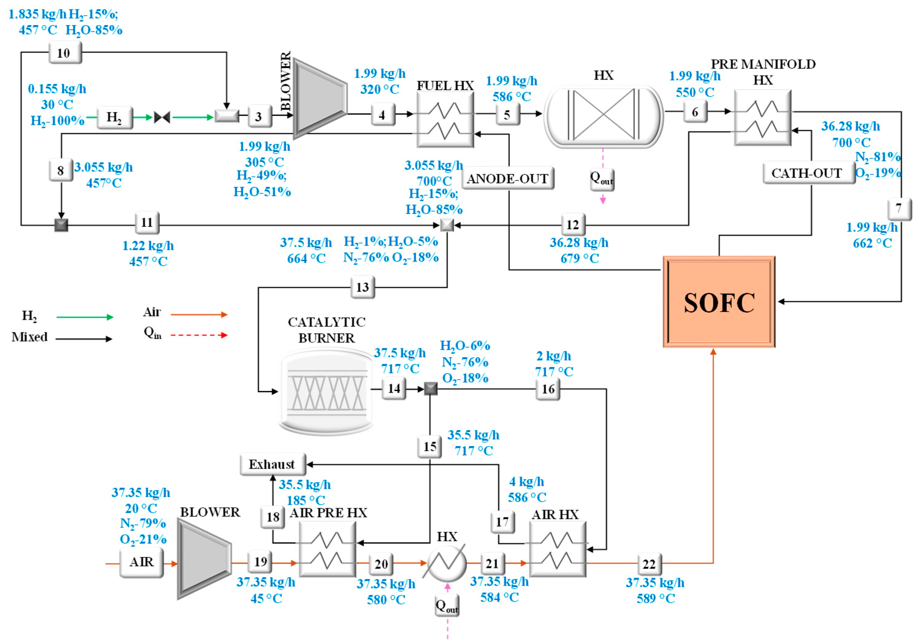
The model of the small-scale system has allowed the calculation of the operating conditions in terms of mass flow rates, chemical compositions, temperatures, and pressures at rated power, considering the feeding of the SOFC unit with ammonia, methanol, or hydrogen. These results can be viewed in the following figures that refer to the system fed by ammonia (
Figure 6), methanol (
Figure 7), and hydrogen (
Figure 8). Details also in terms of flows of chemical composition are summarized in
Table A1,
Table A2,
Table A3,
Table A4,
Table A5 and
Table A6 of the
Appendix A.
Particular attention has been paid to the analysis of the heat exchangers for which the main performances have been calculated as listed in
Table 1. All heat exchangers were modeled assuming a counter-current flow configuration.
The overall performance of the system under consideration of a different fuel supply, in terms of efficiency vs. power, is shown in
Figure 9.
It can be seen that the highest system efficiency, equal to 58% (by considering an inverter efficiency of 97%), is reached by using methanol, while the worst trend efficiency is obtained with hydrogen (51%). Ammonia, instead, reaches an efficiency of about 55%. As for the hydrogen low efficiency, it is mainly due to the highest power consumption of the air blower which is driven by the high air mass flow rate required to ensure an adequate internal cooling of the stack.
The illustrated model results have been compared with the FuelSOME project result, which designed the system within the project FuelSOME. Once the model has been validated, it has been used to predict the performance of a multi-megawatt powertrain in a wide operating range. Considering that the SOFC system is composed of multiple stack modules and that each SOFC stack cannot operate below 50% of its rated power, when the power demand from the ship falls below this threshold, some stack modules are shut down. Through this management strategy, the SOFC power system can operate according to the vessel mission profile.
3.2. Scaling Application for Multi-Megawatt Propulsion System: A Container Ship Case Study
In order to assess the feasibility of integrating a multi-fuel SOFC system as a propulsion system on board a ship, the small-scale system has been scaled up to a real case of a multi-megawatt system. To this end, the case study of an oceangoing vessel has been selected for analysis. Depending on the ship’s characteristics and a selected mission profile, the developed model has been applied to estimate fuel consumption, considering the use of both a single-fuel and a multi-fuel supply solution on board. In both cases, the analysis has been focused on the weight and volume needed to store these fuels.
3.2.1. Container Ship Characterization
The selected container ship has an overall length (LOA) of 134.4 m, a breadth extreme of 22.5 m, a draught of 8.7 m and shows a Dead Weight Tonnage (DWT) of about 11,271 tons. It is equipped with an 8.4 MW main Diesel engine (ME) and uses 3.5 MW auxiliary engines (AEs) [
29]. The selected ship usually operates medium-distance voyages; in particular, for this study, it is considered that a typical voyage is characterized by a cruise duration of 172 h and an average speed of 18.5 knots. This vessel has been chosen because detailed operational and load profile data were available, enabling a reliable feasibility assessment. Its installed power places it in the feeder container segment, which is widely used in short-sea shipping and considered representative of medium-size container vessels.
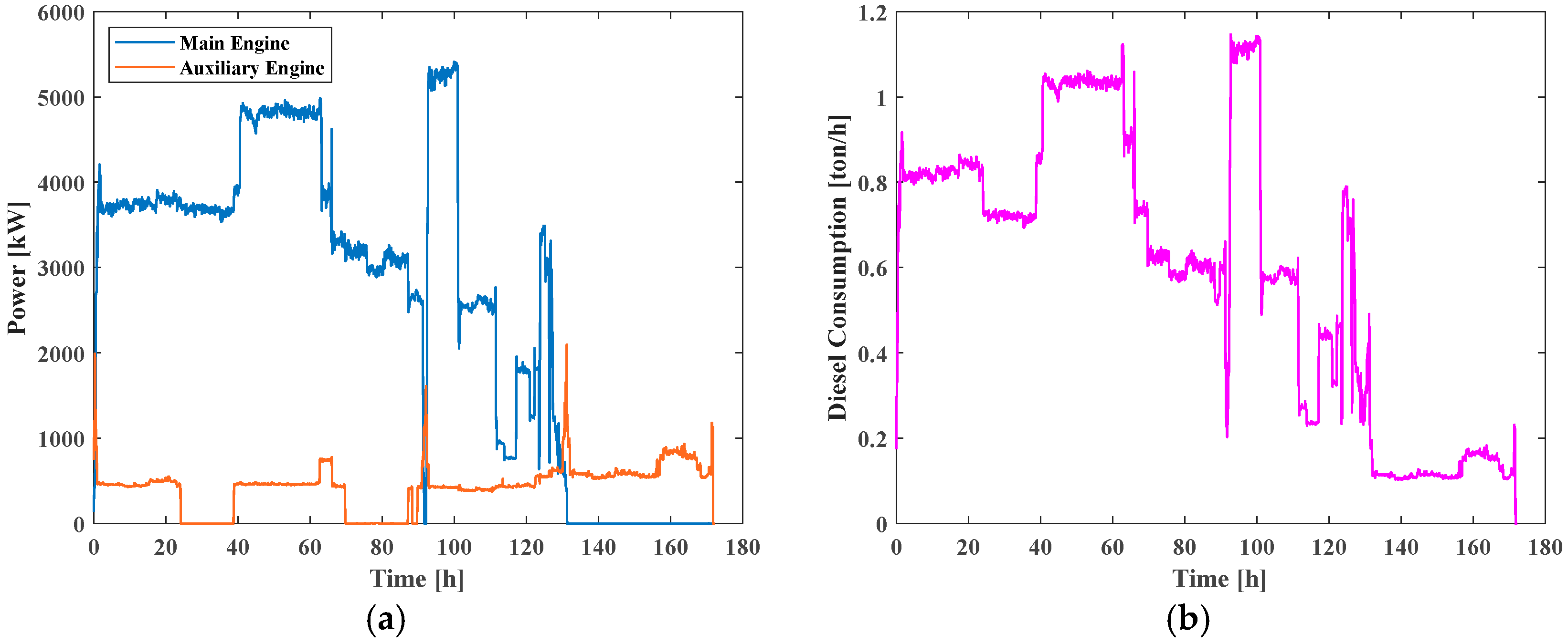
Figure 10a,b depicts the ship load profile and fuel consumption over the single cruise.
The nominal installed power (11.9 MW, including both main and auxiliary engines) is conventionally oversized to ensure safe operation under adverse weather and extreme conditions. As a matter of fact, as shown by the mission load profile (
Figure 10a), the actual operational demand never exceeds about 7.4 MW. Taking this evidence into account, in the present study, the SOFC system adopted to replace the conventional powertrain has been sized at 10 MW, which fully satisfies the real power requirements of the vessel while also providing a safety margin above the maximum observed load.
The selected ship shows an available volume in the fuel compartment of 1646 m3. Taking into account the density of diesel (855 kg/m3) and its low calorific value (45 MJ/kg), the total mass capacity of the tank and its total chemical energy content related to the stored fuel are 1407 tons and 17.6 GWh, respectively. Assuming an average efficiency of 50% for the on board engines, the mechanical energy available for the ship’s propulsion can be calculated (equal to 8.8 GWh). As the amount of diesel required for one voyage (corresponding to approximately 2067 nautical miles) is equal to 102.7 tons, the capacity of the fuel tank allows for approximately thirteen voyages (26,871 nautical miles of autonomy) before refueling.
3.2.2. System Operation with Single-Fuel Tanks for Single Feed Line
Firstly, a feasibility analysis has been carried out in terms of the weight and volume of the tanks for the fuels considered (ammonia, methanol, and hydrogen), which could store, on board, the same chemical energy content as that available in the diesel tank (17.6 GWh).
Table 2 summarizes the results of this estimation, taking into account the weight and volume of both the fuel and the related selected commercial tanks. This table also shows the values for the on board diesel storage.
It is worth noting that in the case of ammonia use, the storage tanks (268 tanks needed) involve an increase in volume and weight with respect to the diesel option of about 373% and 275%, respectively. In the case of hydrogen (97 tanks needed), even if the fuel weight is three times lower compared to the diesel one, the total weight and volume increase drastically due to the characteristics of the liquid hydrogen storage tank. In this study, hydrogen storage has been assumed in the form of cryogenic liquid (−253 °C), as this is considered the most feasible option for large-scale maritime applications, whereas compressed gaseous storage has not been taken into account. This means that to assure the same chemical energy capacity of the stored diesel in the fuel room (17.6 GWh), a reshaping of the ship arrangement is needed.
In the case of methanol, the storage tank does not represent a critical issue since this fuel can be stored in the same tank used for the diesel, which weight can be considered negligible. This assumption relies on the fact that methanol is liquid at ambient pressure and temperature and therefore does not require cryogenic or compressed conditions, additional insulation, or cofferdams; consequently, it can be safely stored in the existing diesel oil tanks without further design modifications. The amount of methanol that could be stored strictly depends on the volume of the on board tank.
3.2.3. System Operation with Multiple Fuel Tanks for Single Feed Line: Alternative Options for Providing More Flexibility
Since the novelty that the FuelSOME project aims to introduce is the use of multi-fuel storage to increase the flexibility of refueling in ports, the feasibility analysis has been carried out by analyzing, through a sensitivity approach, which is the best solution in terms of fuel share that minimizes the weight and volume of an on board multi-fuel storage. In this study, to find the optimal fuel share between ammonia, methanol, and hydrogen, two strategies have been proposed and analyzed: (a) the strategy dedicated for satisfying the fuel room energy capacity (17.6 GWh) and (b) the strategy for the use of the available volume in the fuel room (1646 m3).
Fuel Shares for Satisfying the Fuel Room Energy Capacity
This strategy aims at evaluating the optimal fuel storage share stored on board for minimizing the total weight and volume, once the on board total fuel energy capacity equal to 17.6 GWh is fixed.
With this aim, different scenarios have been evaluated, each considering different percentages of the chemical energy distributed among ammonia, methanol, and hydrogen.
Table 3 summarizes the percentages, in terms of energy distribution in the multi-fuel storage system, for the ten considered scenarios.
In the first scenario, an even energy distribution (the same percentage) among the three fuels (5.87 GWh for each fuel) has been considered. According to these percentages, the amounts of ammonia, methanol, and hydrogen that must be stored are 1193 tons, 1061 tons, and 176 tons, respectively; by considering the weight of the storage tanks, the total weights and volumes are 2228 tons and 2070 m
3 for ammonia, 1061 tons and 1340 m
3 for methanol, and 1154 tons and 4204 m
3 for hydrogen. In the same way, weights and volumes for each scenario have been calculated, as summarized in
Table 4 and illustrated in
Figure 11.
As expected, each scenario involves an increase in volume and weight with respect to the diesel configuration. The best solution in terms of the lowest increase in weight is related to Scenario 9, for which the fuel shares are 10% ammonia, 80% methanol, and 10% hydrogen. In any case, an increase in weight and volume must be taken into account by considering the need for a ship redesign. This option could be pursued if a cargo reduction is considered. In particular, to compensate for the increase in volume, about 89 TEUs have to be removed, corresponding to a reduction of 20.3% in total ship cargo (612 TEU [
25]).
Fuel Shares for Filling the Available Fuel Room Volume
Both the redesign and the cargo reduction required for fixing the chemical energy stored on board are not viable solutions from the ship owner’s point of view, so other strategies need to be considered.
Thus, in this study, the strategy for the use of the available volume in the fuel room (1646 m
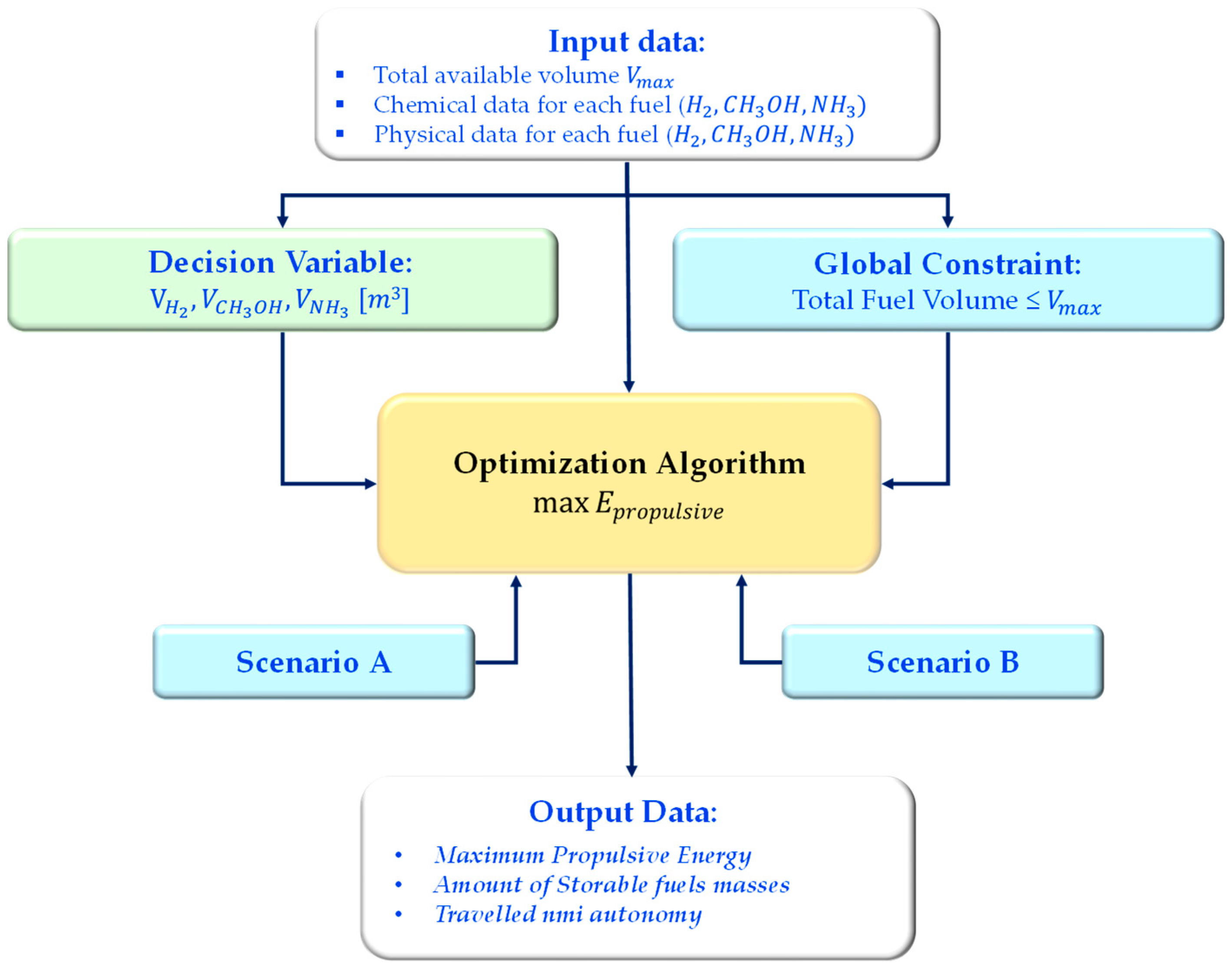
3) has been investigated by searching for the optimal solution that maximizes the chemical energy capacity stored on board. For this purpose, to perform the optimization analysis, a numerical algorithm has been developed in a MATLAB R2024b environment.
Figure 12 depicts the schematic flowchart of the routine.
The optimization problem has been formulated as a linear programming model in the MATLAB Optimization Toolbox. Three decision variables were defined:
representing the storage volumes of hydrogen, methanol, and ammonia, respectively.
The global constraint ensures that the available tank capacity is not exceeded:
The objective function is the maximization of the total propulsive energy and, as a consequence, the corresponding autonomy in terms of traveled nmi:
where
represent the
fuel lower heating value, the system average efficiency operating with the
fuel, and the
fuel density, respectively.
Two different scenarios have been considered, varying in terms of lower bound conditions for the volume tank:
Scenario A: each fuel is constrained to occupy at least 10% of the available tank volume
Scenario B: the lower bounds corresponded to the minimum required stock to cover one complete trip under the reference load profile.
The problem has been solved using the
optimproblem and
optimvar routines of MATLAB with the linear programming solver (linprog). The solution provided the optimal allocation of the mass amount for each fuel (obtained through the objective function and considering the constraint on the maximum volume), along with the corresponding achievable propulsive energy and, consequently, the resulting autonomy in terms of traveled nautical miles (nmi). The results of this optimization procedure are illustrated in
Table 5.
Scenario A consists of fuel shares, in terms of percentage of the fuel room volume, equal to 10% of the volume dedicated to ammonia, 80% to methanol, and 10% to hydrogen storage, respectively. This solution allows us to achieve an available chemical energy of 6.2 GWh, corresponding to a propulsion energy of about 2.97 GWh. Even if this option could be possible from an energetic point of view, it is not applicable since the amounts of ammonia and hydrogen stored are not enough to ensure at least one voyage with each fuel (2067 nmi).
On the other hand, Scenario B is the best, since by considering the fuel shares, in terms of percentage of the fuel room volume, equal to 25% of ammonia, 18% of methanol, and 56% of hydrogen, it ensures at least one voyage with each fuel (2067 nmi). This configuration allows us to the achieve a chemical energy capacity of about 4.2 GWh, corresponding to a total energy for the propulsion with the SOFC power system of 1.9 GWh.
Analyzing Scenario B from the trip autonomy point of view compared to the diesel solution, it can be observed (
Figure 13) that the chemical energy is lower (4.2 GWh vs. 17.6 GWh); therefore, the refueling of the three fuels is required after 7470 nmi when compared with diesel, that allows travel for 26,870 nmi before bunkering.
This is expected, given diesel’s higher volumetric energy density and the maturity/compactness of its storage systems.
However, the lower autonomy of this optimal solution does not represent critical operating conditions since allowing at least one voyage (2067 nmi) with each fuel assures the multi-fuel system’s feasibility, according to the availability of fuels in ports. Moreover, this solution does not involve ship rearrangements as well as cargo capacity reduction since the total mass of stored fuels is reduced by 33% with respect to the conventional diesel solution (334.3 tons vs. 976.7 tons). Moreover, the reduction in autonomy observed for the multi-fuel configuration is offset by lower CO2 emissions, aligning with a core objective of the IMO’s maritime decarbonization strategy.
5. Conclusions
This study demonstrates the technical feasibility of a multi-fuel SOFC-based propulsion system for maritime applications. The system has been designed to operate with three different zero-emission fuels—ammonia, methanol, and hydrogen—offering operational flexibility in response to variable port fuel availability. A thermodynamic model has been developed and validated for a 3 kW prototype and subsequently scaled up to a 10 MW powertrain for application on board a container ship selected as the case study. Modeling results have shown that methanol yields the highest electrical efficiency, reaching 58%, while ammonia and hydrogen configurations achieve slightly lower values due to increased auxiliary power consumption, particularly for air compression.
From an installation feasibility perspective, it has been demonstrated that, when using methanol, the system can be integrated without increasing fuel storage volume or mass, allowing the use of existing diesel tanks. Conversely, ammonia and hydrogen require larger storage capacities and may entail ship rearrangements when used alone. To mitigate these limitations, a multi-fuel storage strategy has been evaluated. An optimized scenario (Scenario B), allocating 25% of ammonia, 18% of methanol, and 56% of hydrogen, has been identified as the best compromise. This configuration enables at least one full voyage (2067 nautical miles) per fuel type, achieving an overall stored energy of 4.2 GWh and avoiding ship redesign or cargo capacity reduction. Additionally, this scenario results in a 33% reduction in the total mass of stored fuels compared to the conventional diesel solution. The feasibility results do not account for the installation of the SOFC propulsion system, as it is still under development and detailed design information is not yet available. In particular, the present study does not include the mass and volume of the SOFC stack, the reformer, or the Balance of Plant, nor the specification of auxiliary equipment (e.g., blowers, recirculation units). These aspects are outside the current scope and will be the subject of future dedicated investigations once detailed design data are available.

