Abstract
As crucial transportation hubs and economic nodes, the underwater security and infrastructure maintenance of harbors are of paramount importance. Harbors are characterized by high vessel traffic and complex underwater environments, where traditional underwater inspection methods, such as diver operations, face challenges of low efficiency, high risk, and limited operational range. This paper introduces a collaborative survey and disposal system that integrates a deformable unmanned surface vehicle (USV) with a lightweight remotely operated vehicle (ROV). The USV is equipped with a side-scan sonar (SSS) and a multibeam echo sounder (MBES), enabling rapid, large-area searches and seabed topographic mapping. The ROV, equipped with an optical camera system, forward-looking sonar (FLS), and a manipulator, is tasked with conducting close-range, detailed observations to confirm and dispose of abnormal objects identified by the USV. Field trials were conducted at an island harbor in the South China Sea, where simulated underwater objects, including an iron drum, a plastic drum, and a rubber tire, were deployed. The results demonstrate that the USV-ROV collaborative system effectively meets the demands for underwater environmental measurement, object localization, identification, and disposal in complex harbor environments. The USV acquired high-resolution (0.5 m × 0.5 m) three-dimensional topographic data of the harbor, effectively revealing its topographical features. The SSS accurately localized and preliminarily identified all deployed simulated objects, revealing their acoustic characteristics. Repeated surveys revealed a maximum positioning deviation of 2.2 m. The lightweight ROV confirmed the status and location of the simulated objects using an optical camera and an underwater positioning system, with a maximum deviation of 3.2 m when compared to the SSS locations. The study highlights the limitations of using either vehicle alone. The USV survey could not precisely confirm the attributes of the objects, whereas a full-area search of 0.36 km2 by the ROV alone would take approximately 20 h. In contrast, the USV-ROV collaborative model reduced the total time to detect all objects to 9 h, improving efficiency by 55%. This research offers an efficient, reliable, and economical practical solution for applications such as underwater security, topographic mapping, infrastructure inspection, and channel dredging in harbor environments.
1. Introduction
As critical hubs for global trade and maritime activities, harbors are often characterized by complex underwater environments with large variations in water depth, high vessel traffic, and significant threats from submerged obstacles. These factors pose considerable difficulties for high-precision, full-coverage hydrographic surveys and the investigation of underwater anomalies, presenting severe challenges to harbor safety and infrastructure [1]. Research indicates that underwater obstacles such as shipwrecks, unexploded ordnance (UXO), and other abandoned artificial objects not only threaten navigational safety but can also lead to structural erosion, topographic changes, and ecological degradation within harbors [2,3]. Therefore, it is of significant importance to develop an underwater object detection and disposal solution suitable for harbor environments.
Traditional underwater survey methods, which rely on divers or manned survey vessels, are increasingly unable to meet the demands of modern harbor security due to their inherent operational limitations, high economic costs, low efficiency, and risks to personnel safety [4,5]. In recent years, the rapid development of marine unmanned systems, particularly USVs and ROVs, has provided innovative solutions for underwater inspection and intervention in harbors [6,7]. Although deep learning-based super-resolution reconstruction methods for FLS imagery enable the detection of marine debris and underwater structures in low-visibility marine environments, their reliance on FLS data results in poor generalization capability, making it challenging to maintain consistent performance across diverse practical applications [8]. USVs offer advantages such as high maneuverability, long endurance, and the ability to carry various sensors like SSS and MBES, making them well-suited for rapid search and mapping missions in complex shallow-water environments [4,9]. Specifically, SSS can efficiently acquire seabed geomorphology and detect small underwater objects, while MBES provides high-resolution bathymetry, backscatter, and water column data. Although deep learning and machine learning methods enable the classification and identification of seabed targets based on SSS imagery [10,11], these approaches typically require extensive datasets and distinct target features. SSS images acquired in port environments often exhibit blurred and morphologically indistinct characteristics, limiting the applicability of such data-driven methods. Nevertheless, SSS imagery has been widely employed for detecting and classifying man-made objects [12,13]. Beyond seabed targets, SSS can also detect targets within the water column, where machine learning methods enhance detection accuracy [14]. Target detection necessitates varying resolution requirements: SSS achieves centimeter-level resolution suitable for small target detection, whereas MBES offer coarser resolution (typically meter-scale), rendering them unsuitable for small target detection but optimal for bathymetric mapping [15,16]. USVs equipped with acoustic sensors can conduct surveys for shipwrecks, marine debris, underwater harbor structures, and seabed topography in areas such as harbors, channels, and islands. Kim and Ryou (2020) demonstrated the effectiveness of a sonar image stabilization algorithm by using a USV autonomous navigation system for the efficient inspection of underwater structures [17]. Papatheodorou et al. (2021) successfully detected vast amounts of seabed litter, including metallic objects and car tires, in the Port of Thessaloniki, Greece, by employing a USV equipped with SSS and automatic object recognition technology [18]. Li et al. (2020, 2021) utilized a USV to conduct simultaneous MBES, SSS, and sub-bottom profiler (SBP) surveys in a harbor environment, efficiently obtaining its bathymetric, geomorphological, and shallow geological characteristics, thereby validating the effectiveness and stability of USVs for harbor operations [19,20]. This study did not evaluate the performance of this system for underwater object detection. However, USVs have difficulty performing close-range, detailed inspections and interventions on seabed objects. Furthermore, information acquired solely from USV acoustic surveys is often insufficient to confirm an object’s material properties and condition, especially when the object is small, non-ferromagnetic, or partially buried. In contrast, ROVs, as tethered underwater platforms capable of precise control, are typically equipped with high-definition cameras, FLS, and intervention tools like manipulators and cutters. They excel at close-range, high-resolution, and precise observation and manipulation tasks, and have been widely applied in deep-sea resource exploration, underwater archaeology, pipeline inspection, and seabed object recovery [10,21,22,23]. Nevertheless, the operational range and survey efficiency of an ROV are limited by its low speed and dependence on a support vessel, rendering it unsuitable for rapid scanning of large harbor areas [21,22]. In summary, both USV and ROV have limitations when performing complex underwater missions alone. A collaborative USV-ROV operational model offers distinct advantages, where the USV rapidly covers a large area to detect and identify acoustic anomalies, followed by the deployment of the ROV for detailed inspection and intervention, thereby enhancing overall operational efficiency. Previous studies have explored various aspects of USV-ROV systems, including remote operation and automatic control [24], control for ROV launch and recovery from an autonomous USV [25], active self-management of the umbilical tether between the ROV and USV [26], adaptive formation control of USV-ROV [27], and modeling of ASV/ROV systems for maritime inspection tasks [28]. However, these studies have remained mainly at the stage of technological validation and simulation of systems and algorithms, without being applied to object detection, identification, and disposal in complex harbor environments that integrate diverse acoustic and optical information.
This study aims to develop and validate the effectiveness and practicality of a collaborative deformable USV-lightweight ROV system for underwater object detection and disposal missions in harbors. The specific research objectives include: (1) To build a collaborative USV-ROV detection and intervention system suitable for complex harbor environments by integrating a deformable USV platform equipped with an Edgetech 6205 combined MBES and SSS, and a lightweight ROV platform equipped with an optical camera, a BlueView M900 FLS, and a small manipulator. (2) To conduct field trials in a harbor in the South China Sea to finely characterize the seabed topography and geomorphology of the harbor area, systematically acquire acoustic and optical signature data of simulated objects (iron drums, plastic drums, and rubber tires), and comprehensively evaluate the performance of the collaborative system in harbor environment surveying, underwater object search, identification, and localization. (3) To thoroughly analyze the technical advantages and potential limitations of the deformable USV and lightweight ROV in a collaborative operational model within a harbor, and to explore future directions for system optimization and technological development, to provide more efficient and reliable technical support for harbor underwater security, regular dredging and maintenance, and emergency response.
2. Materials and Methods
2.1. Unmanned Systems Platform
2.1.1. USV System
The “GMGS-1” deformable USV, developed by the Guangzhou Marine Geological Survey (GMGS) in Guangzhou, China, is primarily composed of the vehicle platform and the mission payload. The USV platform has a length of 2.3 m, a beam of 1.5 m, and a total height of 1.5 m. It has an endurance of 20 km and a communication range of 2 km (Figure 1). The hull integrates a main control module, motor drive modules, a GPS module, a 2.4 GHz radio antenna, cameras, and lead–acid batteries. It can be controlled via a remote controller or a ground control station, featuring functions such as remote control, autonomous navigation, constant speed cruising, automatic return-to-home, automatic obstacle avoidance, mission planning, and status monitoring. With a draft of 0.2 m, the USV is equipped with a depth sounder and high-definition cameras, enabling perception of the underwater, surface, and surrounding environments to ensure the safety of the USV during surveys. The vessel features a deformable design, allowing it to be remotely switched between catamaran and trimaran configurations. This design maximizes hull stability within a compact size, providing a safer and more stable operational environment for the payload. For survey operations, the trimaran mode is used to ensure the payload transducers are fully submerged. In complex environments that may pose a risk to the underwater sensors, the hull can be transformed into a catamaran mode, raising the transducers to ensure their safety. This deformable USV is characterized by its flexibility, durability, and efficiency, offering significant advantages in maneuverability and effectiveness for surveys in shallow-water areas, such as nearshore reefs, harbors, and rivers. The hull parameters and performance specifications of the USV are detailed in Table 1. These parameters fully account for the USV’s endurance, payload capacity, communication range, and deformable hull structure design, making it well-suited for harbor environment detection. Compared to larger USVs, it offers more flexible trajectory movement characteristics, provides enhanced protection for underwater equipment (such as Edgetech 6205 manufactured by Edgetech, West Wareham, MA, USA), and is easier to maintain. Furthermore, to meet the high-resolution requirements for mapping underwater topography and detecting submarine objects in harbor environments, the Edgetech 6205 integrated multi-beam bathymetry and side-scan sonar system was selected, which is capable of detecting and imaging small targets as minute as about 1 cm size.
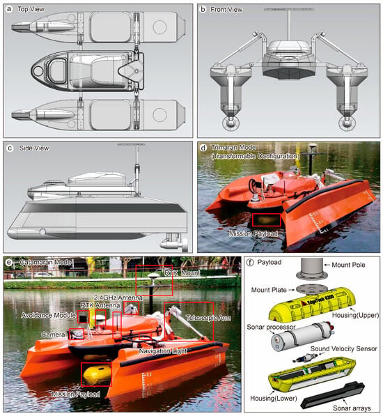
Figure 1.
“GMGS-1” USV and mission payload. (a) Top view of the deformable USV. (b) Front view of the USV. (c) Side view of the USV. (d) The deformable USV in trimaran mode is used for operations to ensure the payload transducers are fully submerged. (e) The USV in catamaran mode, which raises the payload transducers to the water surface. The figure shows the USV’s camera, communication antenna, obstacle avoidance module, retractable arms, and payload. (f) The main components of the underwater section of the Edgetech 6205 sonar payload include the mounting pole, sonar processor, sonar array, and sound velocity sensor.

Table 1.
Specifications of the “GMGS-1” USV.
The USV platform is equipped with an EdgeTech 6205 MBES-SSS system [29] and an SBG Ekinox-D-G3A3 inertial navigation system (INS) [30] to acquire acoustic information, including seabed topography and features. The EdgeTech 6205 is a combined dual-frequency SSS and swath MBES system (Figure 1f). The SSS operates at dual frequencies of 230 kHz and 550 kHz, while the MBES operates at 230 kHz, making it suitable for water depths ranging from 5 to 200 m. The SSS has a range resolution of 3 cm at 230 kHz and 1 cm at 550 kHz. The Edgetech 6205 system includes an underwater sonar unit, a topside unit, a data acquisition computer, and connecting cables. The underwater sonar unit consists of a sonar processing electronics canister, transducer arrays, a sound velocity sensor, a mounting pole, and housing. The system also includes a GPS receiver and the SBG INS. The INS receives MarineStar GPS XP signals (Provided by Fugro, Leidschendam, The Netherlands) to provide stable and precise positioning, heading, attitude, velocity, and timing data to the mission equipment, achieving decimeter-level horizontal and vertical positioning accuracy, as well as roll, pitch, and yaw accuracies of 0.01°. The configuration and connections of the Edgetech 6205 system are shown in Figure 2. The USV’s batteries power the survey system’s topside unit, data acquisition computer, attitude sensor, and GPS via an inverter.
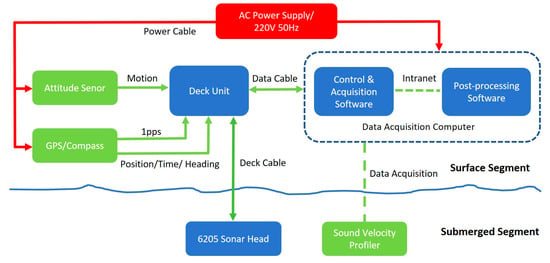
Figure 2.
Connection Diagram of the Edgetech 6205 Sonar System for USV Mission Payloads.
2.1.2. ROV Observation System
The 300 m class “Dolphin II-A” ROV, manufactured by Tianjin Deepinfar Co., Ltd., Tianjin, China, was used. Its main body consists of an underwater power canister, an underwater electronics canister (containing an INS), thrusters, a pan-and-tilt unit, cameras, lights, buoyancy material, and a frame structure (Figure 3). Its performance parameters are detailed in Table 2. The five-function master–slave manipulator features five degrees of freedom, including jaw opening and closing, wrist rotation, elbow bending, shoulder pitching, and shoulder yawing, enabling it to handle underwater objects with a maximum lift capacity of 15 kg. The primary payloads on the Dolphin II-A ROV include a BlueView M900 FLS (Manufactured by Teledyne Marine, Slangerup, Denmark) [31], an Edgetech BATS 4380 (Manufactured by Edgetech, West Wareham, MA, USA) ultra-short baseline (USBL) beacon for underwater positioning [32], and a Tritech PA200 altimeter (Manufactured by Tritech, Westhill, Scotland).
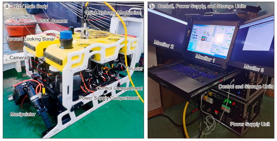
Figure 3.
Main Components of the “Dolphin II-A” ROV. (a) ROV submersible unit. (b) Deck control console.

Table 2.
Performance Specifications of the “Dolphin II-A” ROV.
2.2. Survey Area and Deployment of Simulated Objects
The survey was conducted in a harbor on an island in the South China Sea. The harbor has a water depth ranging from approximately 0.5 to 22 m, an irregular shape with an average length of about 900 m, an average width of 350 m, and an area of about 0.32 km2. The harbor is enclosed by breakwaters, dock and wharf embankments (Figure 4a). Additionally, high vessel traffic in and out of the harbor could potentially interfere with the survey and affect operational efficiency. The survey lines of the USV were deployed parallel to the port shoreline and executed in automatic line-tracking mode. For shallow water areas with obstructions such as reefs and regions with coverage gaps, investigations were conducted through manual remote control of the USV. The survey trajectory of the USV is shown by the yellow line in Figure 4a.
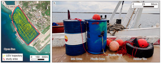
Figure 4.
Harbor location and simulated seabed objects. (a) Satellite remote sensing image of the island harbor, showing the Harbor layout with infrastructural features. The survey trajectory of the USV is indicated by the yellow line; (b) Deployed simulated objects, from left to right: iron drum, plastic drum, and rubber tire.
To validate the underwater object detection capabilities of the collaborative USV-ROV system, artificial objects were randomly deployed within the harbor basin by a third party to simulate typical anomalies. These included an iron drum (58 cm in diameter, 90 cm in height) to simulate metallic objects, a plastic drum (58 cm in diameter, 90 cm in height) to simulate non-metallic objects, and a rubber tire (75 cm in diameter, 25 cm in width) to simulate circular, non-metallic objects (Figure 4b).
2.3. Collaborative Detection and Disposal Methodology
The process of detecting and disposing of underwater objects in the harbor using a support vessel carrying the USV and ROV involved two main phases (Figure 5).
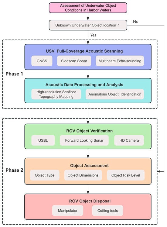
Figure 5.
Flowchart of the USV-ROV survey methodology.
2.3.1. Phase 1: USV Wide-Area Full-Coverage Acoustic Scanning
Before launching the USV, information was collected about the harbor’s piers, shallow shoals, and other features. Full-coverage survey lines for the MBES and SSS were designed based on the presence of anchored and transiting vessels and obstacles in the study area. The survey lines were generally set parallel to the harbor’s breakwaters, with the line spacing adjusted flexibly according to variations in water depth. A USV ground control station was set up on the support mother ship, with the omnidirectional antenna positioned approximately 4 m above the sea surface. The speed of USV was set to 3 knots, and it was operated in autonomous line-tracking mode. The USV’s operational status and sonar data quality were monitored in real time, with manual control available for emergencies. After completing the full-coverage acoustic survey of the harbor, the USV was recovered, its equipment was inspected, and the data were exported.
The MBES and SSS data were processed, and underwater environmental features and anomalous objects were identified manually. MBES bathymetric data were processed using CARIS HIPS and SIPS 8.1 software. The main steps included creating a BASE surface, applying corrections for system parameters, tides, and sound velocity, editing navigation data, removing noisy data points, reconstructing the surface, interpolating the bathymetric surface, and exporting the data. SSS data were processed using SonarWiz 7.11 software, which included the following steps: navigation data processing, bottom tracking, slant range correction, Time-Varying Gain (TVG) adjustment, nadir processing, towfish positioning, geocoding, image resampling, mosaicking, and data export. Processing of MBES bathymetric data yields a high-resolution harbor seafloor bathymetric chart; processing of SSS data facilitates the identification and annotation of anomalous seabed objects, enabling preliminary assessment of object type, morphology, and dimensions, thereby guiding targeted ROV dive verification for specific objects.
2.3.2. Phase 2: ROV Object Verification, Assessment, and Disposal
A circular area with a 15 m radius was defined around each acoustic anomaly. The support vessel, equipped with an underwater positioning system, moved to the vicinity of this area. The ROV was deployed into the water using auxiliary equipment, and a functional check of its manipulator, camera, FLS, and USBL beacon was performed. The ROV was guided to the 15 m radius zone of the acoustic anomaly using the USBL system. Upon arrival, the ROV’s FLS was used to scan the area. Once a sonar highlight was detected, the ROV approached the object to perform multi-angle video recording, determining its position, type, and condition.
The category and potential hazard of the underwater object were assessed. If necessary, the ROV’s manipulator was used to touch or grasp the object. For recovery, the ROV was used to attach a line to the underwater object, which was then hoisted onto the deck of the support vessel.
3. Results
3.1. USV Survey of Harbor Topography and Geomorphology
3.1.1. Accuracy Assessment of Multibeam Bathymetric Data
The USV completed the survey of the harbor area within 6 h. During the multibeam data acquisition, positioning data were collected normally. The survey was conducted progressively in different zones according to actual conditions. The survey line spacing was determined by water depth and swath width to ensure an overlap of more than 10% between adjacent lines. According to the Technical regulations for application of marine multibeam bathymetric survey (DZ/T 0292-2016) [33], the differences at repeated points between main survey lines and check lines, known as depth discrepancies, were calculated to evaluate the accuracy of the depth measurements. According to the specification, for water depths of less than 30 m, the accuracy must be better than 0.3 m; for depths greater than 30 m, the accuracy must be better than 1% of the water depth. The number of depth points exceeding these limits should not exceed 10% of the total points compared. Within the harbor, where water depths are less than 30 m, a comparison of repeated survey lines revealed that all depth discrepancies were within 0.15 m. There were no points with a discrepancy greater than 0.3 m (Table 3), confirming that the measured data meet the specification requirements.

Table 3.
Results of the MBES survey accuracy assessment.
3.1.2. High-Precision 3D Topographic Features of the Harbor Basin
The USV MBES survey covered an area of 0.36 km2, achieving nearly complete coverage except for some shallow, riprap-covered areas, resulting in a 0.5 m × 0.5 m gridded topographic dataset. The water depth in the harbor basin ranges from 0.4 m to 21.4 m. The basin is generally oriented in a northwest–southeast direction, with shallower depths in the northwest and deeper depths in the southeast. Water depth is shallower along the periphery of the basin and increases toward the center (Figure 6a). The topographic units within the basin can be classified into several types: multi-level terraces, multi-level depressions, a flat seabed, submerged reefs, and submerged dikes. Specifically, the multi-level terraces comprise Type I and Type II terraces, while the multi-level depressions encompass Type I, Type II, and Type III depressions (Figure 6b).
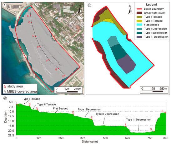
Figure 6.
High-precision topographic map of the harbor basin. (a) High-precision topography of the basin with a 0.5 m × 0.5 m grid. The survey, conducted with a USV-mounted MBES, achieved comprehensive coverage of the harbor basin. Small areas at the margins remained un-surveyed due to extremely shallow water and obstructions from docked vessels. Points A to H are used to mark the turning points of the characteristic topographic features in the harbor basin. (b) Classification and distribution of topography in the basin, primarily including multiple terraces and depressions. (c) Water depth across different terrains, showing distinct features of multiple terraces and depressions. Points A to H correspond to those marked in Figure 6a.
Data analysis reveals that the Type I terrace (Section A–B) has a mean water depth of 6.1 m and a mean slope of 2.9°. The Type II terrace (Section B–C) has a mean water depth of approximately 8.5 m and a mean slope of 2.4°. The flat seabed (Section C–D) has a mean water depth of about 11.2 m and a mean slope of 1.6°. The Type I depression (Section D–E) has a mean water depth of about 13.8 m and a mean slope of 1.4°. The Type II depression (Section E–F) has a mean water depth of about 17.5 m and a mean slope of 1.3°. The Type III depression (Section F–G) has a mean water depth of about 21.2 m and a mean slope of 1.2°. Section G–H exhibits a water depth difference of 9.5 m (Figure 6c). The topography within each type of geomorphic unit is very flat, with the maximum slope not exceeding 2.9°. However, at the boundaries between different topographic units, the slope reaches 13° (Figure 6c). A negative correlation exists between the harbor basin’s water depth and slope; as the water depth increases, the slope generally decreases. Numerical fitting of the water depth and slope data shows that a second-degree polynomial fit (R2 = 0.9763) conforms more closely to the actual data trend than a linear fit (R2 = 0.8008). This indicates that the slope decreases rapidly across the terrace terrains, whereas the rate of slope decrease becomes more gradual upon entering the depression terrains (Figure 7). The slope and depth characteristics of the harbor basin show very distinct evidence of artificial excavation.
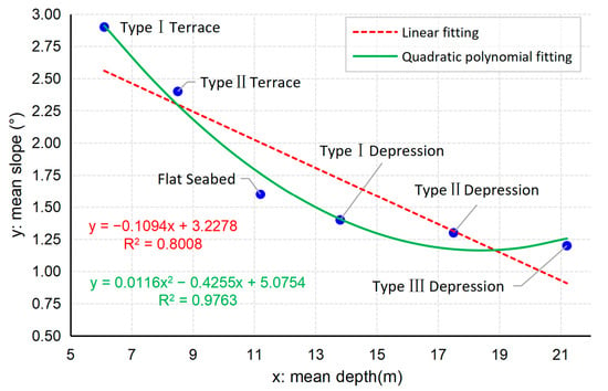
Figure 7.
Relationship between water depth and slope for different topographic units. Numerical fitting of depth and slope shows that a second-order polynomial fit better represents the actual trend compared to a linear fit, indicating that the depth–slope relationship is not strictly linear. The slope decreases rapidly across the terraces and then more gradually upon entering the depression zones.
3.2. USV Detection of Underwater Objects in the Harbor
3.2.1. Acoustic Characteristics of Simulated Underwater Objects
The SSS mosaic acquired by the USV revealed the geomorphological features of the seabed and the acoustic characteristics of various underwater objects (Figure 8a). Three types of simulated objects—the iron drum, plastic drum, and rubber tire—were all correctly identified. These anomalies exhibited distinct shapes, sizes, and acoustic shadows that were distinct from those of the surrounding environment. An initial SSS survey of the entire harbor basin was conducted prior to the deployment of the objects. After deployment, the basin was surveyed again with the SSS. Once the simulated objects were identified, the USV was used again to survey the acoustic anomalies from different angles, verifying the findings and enhancing the reliability of the acoustic identification.
The three simulated objects were scanned a total of five times. The iron and plastic drums were identified in all five scans, while the rubber tire was identified in only three scans. The locations where the simulated objects were identified are marked with blue circles in the Figure 8b and Figure 9. The average positional deviations between multiple scans for the identified acoustic anomalies of the iron drum, plastic drum, and rubber tire were 1.3 m, 1.9 m, and 2.2 m, respectively.
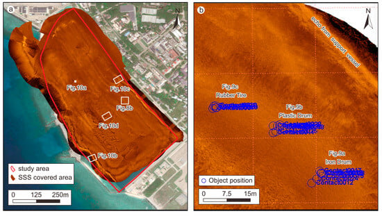
Figure 8.
Complete SSS coverage of the harbor and the identified locations of simulated objects. (a) Displays the SSS coverage within the harbor. The locations corresponding to Figure 8b and Figure 10a–d are also indicated. (b) Shows the locations of the iron drum, plastic drum, and rubber tire as identified by SSS, with identification reliability enhanced through five separate SSS scans.
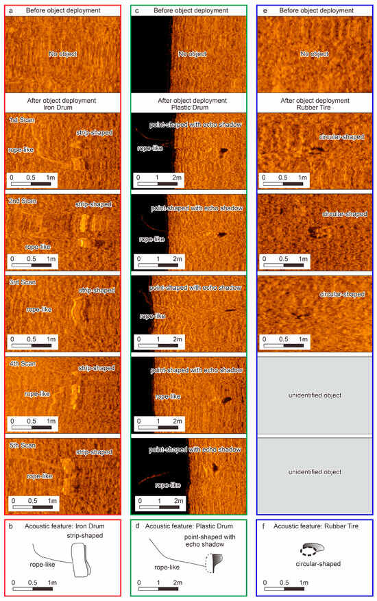
Figure 9.
SSS reveals the acoustic characteristics of the seabed before and after the deployment of simulated objects. (a,b) The acoustic signature of the iron drum; (c,d) The acoustic signature of the plastic drum; (e,f) The acoustic signature of the rubber tire.
In the SSS imagery, the iron drum appeared as an elongated, extremely strong echo. The acoustic shadow behind this strong echo was indistinct, suggesting an elongated object lying flat on the seabed. It measured approximately 1 m in length and 0.5 m in width, with a rope-like object attached (Figure 9a,b). Due to its material, the plastic drum had a relatively weaker acoustic reflection, appearing as an elongated strong echo followed by a distinct acoustic shadow, which indicated an upright object. It measured approximately 1 m in length and 0.5 m in width, with a visible rope-like object attached (Figure 9c,d). The acoustic signature of the rubber tire was characterized by a circular pattern of scattered, weak echoes, forming a ring with a diameter of about 0.5 m (Figure 9e,f). The acoustic characteristics of the three pre-deployed underwater objects are summarized in Table 4.

Table 4.
Acoustic Characteristics of Simulated Seabed Objects.
3.2.2. Acoustic Characteristics of Other Underwater Objects in the Harbor
Overall, the seabed sediment was homogeneous within the same geomorphological unit of the harbor basin, with no significant seabed obstructions and few anomalous features observed. Other objects that were present differed in size and acoustic characteristics from the confirmed simulated objects.
A large, isolated giant reef with a diameter reaching 2.7 m was discovered in the central part of the harbor basin, characterized by a bright-to-dark variation in echo intensity (Figure 10a). In the northern and southwestern parts of the basin, SSS images revealed extensive, disorganized piles of breakwater or reef. Their acoustic signature was characterized by high variability in echo intensity, in stark contrast to the uniform echo of the flat seabed. The front faces of the riprap produced strong backscatter, while the back faces produced weak echoes; larger rocks even cast distinct acoustic shadows (Figure 10b). The northeastern side of the basin is bordered by wharf embankment, which appeared as a regular linear feature with highly variable echo intensity in the SSS data. The face of the wharf embankment generated an extremely strong backscatter echo, while the area behind it was almost devoid of echoes, creating a prominent acoustic shadow zone (Figure 10c). At the boundaries between different geomorphological units within the basin, sudden changes in water depth formed escarpments, whose acoustic features were captured by the SSS (Figure 10d).
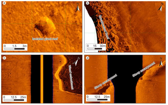
Figure 10.
Acoustic characteristics of other underwater objects in the harbor basin where the location is shown in Figure 8a. (a) A large, isolated giant reef occasionally found in the central, seaward side (west) of the harbor basin. (b) Acoustic characteristics of the breakwater or reef, and the flat seabed on the western side of the harbor basin. (c) Acoustic characteristics of the wharf embankment and the flat seabed. (d) Acoustic characteristics of the steep escarpment terrain in the central part of the harbor basin.
3.3. ROV Object Confirmation and Disposal
The ROV completed the confirmation and disposal of the simulated objects within the harbor in 3 h. Initially, based on the locations of the iron drum, plastic drum, and rubber tire identified by the SSS (Figure 9), a search area with a 15 m radius was designated for the ROV. Subsequently, the ROV’s FLS was used to determine the approximate bearing and distance of the objects. This effectively guided the ROV to approach the objects for final confirmation and disposal.
On the FLS, the simulated seabed objects primarily appeared as bright spots (Figure 11). The iron drum exhibited the strongest backscatter intensity, appearing as a strong highlight when it was approximately 9 m from the ROV (Figure 11a). The plastic drum’s backscatter was weaker than that of the iron drum; at a distance of approximately 4 m from the ROV, it appeared as a bright spot, and due to its upright position, a clear acoustic shadow was visible behind it (Figure 11b). The rubber tire had the weakest backscatter, appearing as a smaller bright spot at a distance of about 6 m from the ROV (Figure 11c).
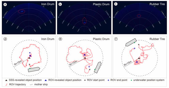
Figure 11.
Response of the ROV’s FLS to the simulated underwater objects. (a) The primary acoustic feature of the iron drum is a strong, bright spot. (b) The primary acoustic features of the upright plastic drum are a bright spot and a shadow behind it. (c) The primary acoustic feature of the rubber tire is a small bright spot. (d–f) Positional deviation between the SSS-determined location and the actual location discovered by the ROV for the simulated objects. The black triangle indicates the object position found by SSS, with a 15 m radius search area defined for the ROV; the red line represents the ROV’s trajectory. The positional deviation value is calculated from the distance between the blue and black triangles.
The underwater visibility was approximately 3 m, requiring the ROV to approach the objects closely to observe and confirm their positions. By analyzing the ROV’s underwater positioning track, the positional discrepancy between the SSS location and the ROV’s actual confirmed position was found to be approximately 1.9 m for the iron drum (Figure 11d), 2.6 m for the plastic drum (Figure 11e), and 3.2 m for the rubber tire (Figure 11f). Overall, with guidance from the FLS, all simulated objects were relatively easy to find and locate.
After approaching the objects, the ROV conducted optical imaging to obtain clear imagery of the simulated objects (Figure 12). The iron drum was lying flat on the seabed, with a rope attached. The brand logo and text on the drum were visible (Figure 12a). The plastic drum was in a nearly upright position, swaying slightly, with a rope attached to it. The drum was blue, with several holes visible on its body, and its label and text were also visible (Figure 12b). The rubber tire was lying flat on the seabed with a rope attached, and the brand and text on the tire were visible (Figure 12c). All simulated objects were successfully located and confirmed by the ROV.
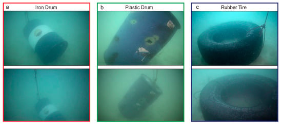
Figure 12.
Optical camera images of the simulated underwater objects. (a) The iron drum, with its logo visible. (b) The plastic drum has legible text on its label and distinct holes on its body. (c) The rubber tire, with its text visible.
The ROV’s manipulator was operated to touch and grasp the objects. Finally, by attaching ropes via the ROV, all simulated objects within the harbor basin were recovered.
4. Discussion
4.1. Performance Evaluation of the USV-ROV System in a Harbor Environment
The USV-ROV collaborative system demonstrated effective object detection capabilities, positioning accuracy, and operational efficiency within the complex underwater harbor environment, meeting the requirements for underwater object investigation in such settings adequately. Compared to USVs developed by previous researchers [3,18,20], the transformable design of the USV reduces the risk of its MBES and SSS transducer heads making contact with the seabed in complex harbor topographies. The combination of MBES and SSS on the USV proved to be an effective tool for rapid seabed mapping and anomaly detection in the harbor. The USV acquired high-resolution (0.5 m × 0.5 m) 3D topographic data of the harbor, revealing its bathymetric features (Figure 6 and Figure 7). The SSS detected and identified the deployed objects, including the iron drum, plastic drum, and rubber tire (Figure 9), with repeated survey scans indicating a maximum positioning deviation of 2.2 m. However, the identification of small, materially similar, or partially buried objects, such as the large boulders or irregularly shaped reefs in the harbor basin (Figure 10a,b), still relies on manual interpretation, indicating a deficiency in intelligent object recognition.
In contrast to a full-area search conducted solely by an ROV, which would require approximately 20 h, the USV-ROV operational model reduced the time to scan, identify, and confirm all objects to 9 h, marking a significant improvement in efficiency (Table 5). The ROV utilized high-definition optical imagery to confirm the attributes of objects like the iron drum, plastic drum, and rubber tire, thereby compensating for the uncertainties inherent in acoustic detection (Figure 11). The maximum deviation between the SSS-derived positions of the simulated objects and the USBL positions obtained by the ROV was 3.2 m (Figure 11). In the turbid water conditions of the harbor, the ROV’s onboard USBL and FLS were crucial for close-range object acquisition. While this study verified the ROV’s capability to handle different objects, it was equipped with only a simple manipulator. It lacked specialized tools for tasks such as cutting or complex gripping, indicating a need for future optimization. Overall, this USV-ROV integrated system, which combines the large-area acoustic survey capabilities of the USV with the close-range, high-resolution optical and acoustic inspection and intervention capabilities of the ROV, effectively reduces personnel risks and economic costs. It enhances the efficiency and reliability of underwater environmental management in harbors, making routine inspections of harbor waters feasible.

Table 5.
Comparison Between USV-ROV System Detection and Conventional Underwater Object Detection Methods.
4.2. Limitations and Future Research
This study conducted a practical trial of a USV and ROV for underwater object detection in a complex harbor environment, providing a viable solution for harbor inspections. However, this study has certain limitations and shortcomings. The harbor environment for this test was relatively ideal. Real-world harbor environments may feature high vessel traffic, lower water visibility, and a more diverse range of buried objects of various types and sizes. These factors could potentially reduce the operational efficiency and detection performance of the USV-ROV system. The current approach primarily utilizes data from MBES, SSS, and optical cameras for object detection, but it cannot detect buried objects. Furthermore, the detection and identification of seabed objects still rely on manual interpretation. Future work should focus on integrating data from multi-source sensors, such as underwater laser scanners, magnetometers, and stereo cameras, and developing multi-modal data fusion and object recognition algorithms [8,15,34,35,36]. This will enhance the capability of the USV-ROV system for precise detection and identification of small objects in turbid water environments.
Currently, the collaborative operation of the USV and ROV is primarily achieved through manual control, with the USV and ROV still acting as relatively independent operational units. Future efforts should be directed towards the development of an integrated USV-ROV system to achieve autonomous underwater object recognition by the USV, which can then automatically guide the ROV for confirmation and intervention [37]. Moreover, there is a need to develop operational tools designed explicitly for lightweight ROVs in harbor environments, such as cutters, underwater drills, and cleaning brushes, to expand the applications of the USV-ROV collaborative system.
5. Conclusions
This study designed and validated a collaborative USV-ROV system for underwater object detection and disposal in a harbor. Through field trials in a harbor on an island in the South China Sea, the system was proven to effectively integrate the wide-area acoustic search capability of the USV with the close-range, high-resolution observation and intervention capabilities of the ROV. The experimental results demonstrate that the collaborative system can perform the detection, localization, identification, and disposal of typical underwater objects in harbor waters with high efficiency, accuracy, and cost-effectiveness, offering significant advantages over traditional methods or single unmanned platforms. This research offers a practical unmanned solution for tasks such as underwater harbor security monitoring, channel clearance, infrastructure maintenance, and emergency response. The collaborative USV-ROV operational model is poised to become an important component in the development of future smart harbors. Future work will concentrate on enhancing the system’s level of autonomous collaboration, improving its adaptability to complex environments, and expanding its physical intervention capabilities.
Author Contributions
Conceptualization and methodology, Y.L., M.W. and H.Y.; sample collection, Y.L., P.W., Z.M. and D.W.; formal analysis, Y.L., D.W., J.C., H.Z., S.Z. and H.Y.; writing—original draft preparation, Y.L. and D.W.; writing—review and editing, Y.L., M.W., P.W. and Z.M. All authors have read and agreed to the published version of the manuscript.
Funding
This research was supported by National Key R&D Program of China (Grant No. 2023YFC2808700).
Data Availability Statement
Data are available upon request from the author, Y.L. (liyonghang@mail.cgs.gov.cn).
Conflicts of Interest
The authors declare no conflicts of interest.
References
- Alyami, H.; Lee, P.T.-W.; Yang, Z.; Riahi, R.; Bonsall, S.; Wang, J. An Advanced Risk Analysis Approach for Container Port Safety Evaluation. Marit. Policy Manag. 2014, 41, 634–650. [Google Scholar] [CrossRef]
- Pessanha Santos, N.; Moura, R.; Sampaio Torgal, G.; Lobo, V.; Neto, M.D.C. Side-Scan Sonar Imaging Data of Underwater Vehicles for Mine Detection. Data Brief 2024, 53, 110132. [Google Scholar] [CrossRef]
- Specht, C.; Śliwińska, D. Hydrographic Inspection Using a USV of a Harbour Bottom Deepened by the Periodic Actuation of SAR Vessel Propellers. Remote Sens. 2024, 16, 2522. [Google Scholar] [CrossRef]
- Howard, V.; Mefford, J.; Arnold, L.; Bingham, B.; Camilli, R. The Unmanned Port Security Vessel: An Autonomous Platform for Monitoring Ports and Harbors. In Proceedings of the OCEANS’11 MTS/IEEE KONA., Waikoloa, HI, USA, 19–22 September 2011; pp. 1–8. [Google Scholar]
- Radu, O.; Slămnoiu, G.; Zărnescu, L.; Coşereanu, L. Harbor Protection Against Terrorist Threats: Difficulties and Possible Solutions. In Proceedings of the RTO Systems Concepts and Integration Symposium, Ottawa, ON, Canada, 25–27 September 2006. [Google Scholar]
- Kitowski, Z. Selection of UUV Type ROV Equipment and Cooperation System with USV “Edredon” in Protection Tasks of Ports and Critical Objects. Trans. Marit. Sci. 2019, 8, 198–204. [Google Scholar] [CrossRef]
- Villa, J.; Aaltonen, J.; Virta, S.; Koskinen, K.T. A Co-Operative Autonomous Offshore System for Target Detection Using Multi-Sensor Technology. Remote Sens. 2020, 12, 4106. [Google Scholar] [CrossRef]
- Zhou, X.; Mizuno, K. Acoustic Camera-Based Super-Resolution Reconstruction Approach for Underwater Perception in Low-Visibility Marine Environments. Appl. Ocean Res. 2024, 150, 104110. [Google Scholar] [CrossRef]
- Jorge, V.A.M.; Granada, R.; Maidana, R.G.; Jurak, D.A.; Heck, G.; Negreiros, A.P.F.; Dos Santos, D.H.; Gonçalves, L.M.G.; Amory, A.M. A Survey on Unmanned Surface Vehicles for Disaster Robotics: Main Challenges and Directions. Sensors 2019, 19, 702. [Google Scholar] [CrossRef]
- Du, X.; Sun, Y.; Song, Y.; Sun, H.; Yang, L. A Comparative Study of Different CNN Models and Transfer Learning Effect for Underwater Object Classification in Side-Scan Sonar Images. Remote Sens. 2023, 15, 593. [Google Scholar] [CrossRef]
- Dura, E. Image Processing Techniques for the Detection and Classification of Man Made Objects in Side-Scan Sonar Images. In Sonar Systems; Kolev, N., Ed.; InTech: Rijeka, Croatia, 2011; ISBN 978-953-307-345-3. [Google Scholar]
- Georgiev, I. 3D Object Detection Using Sidescan Sonar Images. Master’s Thesis, KTH Royal Institute of Technology, Stockholm, Sweden, 2024. [Google Scholar]
- Lubis, M.Z.; Kausarian, H.; Anurogo, W. Seabed Detection Using Application of Image Side Scan Sonar Instrument (Acoustic Signal). J. Geosci. Eng. Environ. Technol. 2017, 2, 230. [Google Scholar] [CrossRef]
- Niu, H.; Li, X.; Zhang, Y.; Xu, J. Advances and Applications of Machine Learning in Underwater Acoustics. Intell. Mar. Technol. Syst. 2023, 1, 8. [Google Scholar] [CrossRef]
- Pailhas, Y.; Petillot, Y.; Capus, C. High-Resolution Sonars: What Resolution Do We Need for Target Recognition? EURASIP J. Adv. Signal Process. 2010, 2010, 205095. [Google Scholar] [CrossRef][Green Version]
- Zhao, J.; Meng, J.; Zhang, H.; Yan, J. A New Method for Acquisition of High-Resolution Seabed Topography by Matching Seabed Classification Images. Remote Sens. 2017, 9, 1214. [Google Scholar] [CrossRef]
- Kim, Y.; Ryou, J. A Study of Sonar Image Stabilization of Unmanned Surface Vehicle Based on Motion Sensor for Inspection of Underwater Infrastructure. Remote Sens. 2020, 12, 3481. [Google Scholar] [CrossRef]
- Papatheodorou, G.; Kosmopoulou, A.; Fakiris, E.; Geraga, M.; Dimas, X.; Maurommatis, N.; Christodoulou, D.; Kouvara, K.; Xirotagarou, P. Benthic Megalitter Detection Using Unmanned Surface Vehicle (USV) and Automatic Target Detection: A Case Study in the Port of Thessaloniki, Thermaikos Gulf. In Proceedings of the 17th International Conference on Environmental Science and Technology, Athens, Greece, 1–4 September 2021. [Google Scholar]
- Li, Y. Application of UAV and USV in Joint Survey of the Submarine and Land Geomorphology in Dongluo Island, Hainan. Mar. Geol. Front. 2021, 37, 80–88. [Google Scholar] [CrossRef]
- Li, Y.; Shan, C.; Su, M.; Liu, W.; Lei, Y.; Wen, M.; Cai, P. Application of Acoustic Unmanned Surface Vehicle to Submarine Geomorphology Survey in Shallow Water. Mar. Geol. Quat. Geol. 2020, 40, 219–226. [Google Scholar] [CrossRef]
- Li, Y.; Yao, H.; Chen, Z.; Wang, L.; Zhou, H.; Zhang, S.; Zhao, B. Detailed Investigation of Cobalt-Rich Crusts in Complex Seamount Terrains Using the Haima ROV: Integrating Optical Imaging, Sampling, and Acoustic Methods. J. Mar. Sci. Eng. 2025, 13, 702. [Google Scholar] [CrossRef]
- Reed, S.; Wood, J.; Vazquez, J.; Mignotte, P.-Y.; Privat, B. A Smart ROV Solution for Ship Hull and Harbor Inspection. In Proceedings of the SPIE Defense, Security, and Sensing, Orlando, FL, USA, 5–9 April 2010; Carapezza, E.M., Ed.; SPIE: Bellingham, WA, USA, 2010; p. 76662G. [Google Scholar]
- Sun, B.; Pang, W.; Chen, M.; Zhu, D. Development and Experimental Verification of Search and Rescue ROV. Intell. Robot. 2022, 2, 355–370. [Google Scholar] [CrossRef]
- Nava-Balanzar, L.; Sanchez-Gaytán, J.L.; Fonseca-Navarro, F.; Salgado-Jiménez, T.; Garcia-Valdovinos, L.G.; Rubio-Lopez, O.; Gómez-Espinosa, A.; Ramirez-Martinez, A. Towards Teleoperation and Automatic Control Features of an Unmanned Surface Vessel-ROV System: Preliminary Results. In Proceedings of the 14th International Conference on Informatics in Control, Automation and Robotics, Madrid, Spain, 26–28 July 2017; SCITEPRESS—Science and Technology Publications: Setúbal, Portugal, 2017; pp. 292–299. [Google Scholar]
- Tran, C.; Gushkov, I.; Nordvik, K.; Røang, S.T.; Lysthaug, S.B.; Ommani, B.; Fossen, T.I.; Hassani, V.; Smines, V.; Johansen, T.A. Operability Analysis of Control System for ROV Launch-and-Recovery from Autonomous Surface Vessel. Ocean Eng. 2023, 277, 114272. [Google Scholar] [CrossRef]
- Tortorici, O.; Anthierens, C.; Hugel, V.; Barthelemy, H. Towards Active Self-Management of Umbilical Linking ROV and USV for Safer Submarine Missions. IFAC Pap. 2019, 52, 265–270. [Google Scholar] [CrossRef]
- Zhang, Q.; Zhang, S.; Liu, Y.; Zhang, Y.; Hu, Y. Adaptive Terminal Sliding Mode Control for USV-ROVs Formation under Deceptive Attacks. Front. Mar. Sci. 2024, 11, 1320361. [Google Scholar] [CrossRef]
- Zhao, C.; Thies, P.R.; Johanning, L. Offshore Inspection Mission Modelling for an ASV/ROV System. Ocean Eng. 2022, 259, 111899. [Google Scholar] [CrossRef]
- EdgeTech. 6205 Bathymetry and Side Scan System User Hardware Manual; EdgeTech: West Wareham, MA, USA, 2017. [Google Scholar]
- SBG Systems. EKINOX 2 Surface Series Tactical Grade MEMS Inertial Sensors Hardware Manual; SBG Systems: Carrières-sur-Seine, France, 2018. [Google Scholar]
- Teledyne Marine. BlueView M900 Mk2 Product Leaflet; Teledyne Marine: Slangerup, Denmark, 2021. [Google Scholar]
- EdgeTech. Operation and Maintenance Manual for the Edgetech USBL Broadband Acoustic Tracking System (BATS); EdgeTech: West Wareham, MA, USA, 2012. [Google Scholar]
- DZ/T 0292-2016; Ministry of Land and Resources, PRC. Technical Regulations for Application of Marine Multibeam Bathymetric Survey (DZ/T 0292-2016). Guangzhou Marine Geological Survey, China Geological Survey: Beijing, China, 2016.
- Cheng, J.; Tian, M.; Liu, J.; Zhang, H.; Dong, C. Sonar Image Target Detection Based on YOLOX. J. Inf. Eng. Univ. 2023, 24, 385–390. [Google Scholar] [CrossRef]
- Mi, Y.; Chi, M.; Zhang, Q.; Liu, P. Research on Multi-Scale Fusion Image Enhancement and Improved YOLOv5s Lightweight ROV Underwater Target Detection Method. Sci. Rep. 2024, 14, 28280. [Google Scholar] [CrossRef] [PubMed]
- Yu, Y.; Zhao, J.; Gong, Q.; Huang, C.; Zheng, G.; Ma, J. Real-Time Underwater Maritime Object Detection in Side-Scan Sonar Images Based on Transformer-YOLOv5. Remote Sens. 2021, 13, 3555. [Google Scholar] [CrossRef]
- Pandian, P.K.; Ruscoe, J.P.; Shields, M.; Side, J.C.; Harris, R.E.; Kerr, S.A.; Bullen, C.R. Seabed Habitat Mapping Techniques: An Overview of the Performance of Various Systems. Mediterr. Mar. Sci. 2009, 10, 29. [Google Scholar] [CrossRef]
Disclaimer/Publisher’s Note: The statements, opinions and data contained in all publications are solely those of the individual author(s) and contributor(s) and not of MDPI and/or the editor(s). MDPI and/or the editor(s) disclaim responsibility for any injury to people or property resulting from any ideas, methods, instructions or products referred to in the content. |
© 2025 by the authors. Licensee MDPI, Basel, Switzerland. This article is an open access article distributed under the terms and conditions of the Creative Commons Attribution (CC BY) license (https://creativecommons.org/licenses/by/4.0/).