Article

Design of UUV Underwater Autonomous Recovery System and Controller Based on Mooring-Type Mobile Docking Station

College of Intelligent Systems Science and Engineering, Harbin Engineering University, Harbin 150001, China
*
Author to whom correspondence should be addressed.
J. Mar. Sci. Eng. 2025, 13(10), 1861; https://doi.org/10.3390/jmse13101861
Submission received: 18 August 2025 / Revised: 9 September 2025 / Accepted: 22 September 2025 / Published: 26 September 2025
(This article belongs to the Special Issue Design and Application of Underwater Vehicles)

Abstract

This study addresses autonomous underwater vehicle (UUV) recovery onto dynamic docking stations by proposing a fork-column recovery control system with a segmented docking strategy (long-distance approach + guided descent). To enhance model fidelity, transmission lag of actuators is captured by a specified transfer function, and nonlinear dynamics are characterized as an improved quasi-linear parameter-varying (QLPV) model. An adaptive variable–prediction–step mechanism was designed to accommodate different phases of acoustic–optical guided recovery. A model predictive controller (MPC) was developed based on an improved dynamic model to effectively handle complex constraints during the recovery process. Simulation and physical experiments demonstrated that the proposed system significantly reduces errors, among which the control accuracy (tracking error under disturbance < 0.3 m) and docking success rate (>95%) are notably superior to traditional methods, providing a reliable solution for the dynamic recovery of unmanned underwater vehicles (UUVs).

1. Introduction

Underwater Unmanned Vehicles (UUVs), as one of the critical components of unmanned underwater systems, are submersible craft capable of prolonged underwater operations. These self-powered, self-propelled, and autonomously controlled vehicles can perform various missions through configured payloads, while being recoverable and reusable [1]. However, due to the limitations of the UUV’s own energy supply, when a UUV exhausts its power while surveying a fixed seabed area, resurfacing for recovery and recharging would significantly compromise operational efficiency. Moreover, each surfacing–resubmergence cycle necessitates re-localization of the previous survey termination point, which not only jeopardizes positioning accuracy but also consumes substantial energy on non-productive maneuvers [2]. Furthermore, the recovery of UUVs is not a straightforward task. Current commonly used recovery methods, such as surface crane-based retrieval, must account not only for wave and wind disturbances but also for the safety of personnel and equipment during the operation [3]. This recovery method also suffers from poor maneuverability and low stealth capability during UUV mission execution [4]. Consequently, underwater dynamic recovery of UUVs has emerged as a critical technology requiring urgent research.
However, the dynamic-base docking method of UUV underwater imposes high requirements on control. It not only involves the design of docking controllers under conditions including high nonlinearity and multi-degree-of-freedom coupling of the UUV dynamic system but also needs to take into account complex constraint issues during UUV docking, such as boundary constraints, observation constraints, and actuator constraints [5,6].
Model Predictive Control (MPC) has the capability to effectively handle complex constraint problems [7,8]. Zhang et al. [9], addressed the three-dimensional tracking control problem of UUVs under random ocean current disturbances by proposing a tracking controller based on Model Predictive Control (MPC). They transformed the trajectory tracking problem into a standard convex quadratic programming problem that can be computed online, effectively accounting for the practical constraints on system inputs and states. Zhang Wei et al. [10], applied the model predictive control approach to the close-range horizontal relative motion process between the UUV and its mother platform. They designed a hierarchical satisfactory model predictive control method to improve the real-time performance of the control system. The feasibility of the algorithm was verified through pool experiments. Huang et al. [11] designed a dual-mode model predictive control (DMPC) strategy for the depth-keeping control of UUVs. By leveraging the vehicle’s onboard actuators, their approach enables seamless switching between two control modes: buoyancy adjustment and center-of-gravity regulation. This method effectively decouples the system model to a certain extent. Chen et al. [12], designed a Linear Time-Varying (LTV)-MPC controller for an underwater mining vehicle. They employed Jacobian linearization to derive a discrete-time expression of the kinematic model and verified the effectiveness of their method through simulations.
However, there are many nonlinear components in the dynamic model of UUV, and more factors need to be considered in practical applications. Improper handling of these factors will lead to a significant reduction in the control performance of Model Predictive Control (MPC). However, previous studies on UUVs have mostly focused on improving the solving capability of MPC, while research on model processing is relatively insufficient. Some studies even only use simplified kinematic models for the design of tracking controllers, resulting in low reliability. In addition, many related studies on MPC are based on land vehicles [13,14,15] and aircraft [16,17,18], but they also have high reference value.
Research on corresponding technologies aiming at existing problems has significant engineering application value for the underwater dynamic docking of unmanned underwater vehicles (UUVs). In response to this, this paper focuses on in-depth research into the following key technical challenges and achieves the following main innovations:
  • A fork-pillar-type recovery system was designed for dynamic docking of UUVs. Considering the characteristics of the docking device, a segmented sit-down docking strategy was developed, consisting of two phases: a long-distance approach phase and a follow-up descent phase.
  • To address the accuracy issues of the UUV model, a transfer-function-based representation was designed and incorporated into the UUV model to mitigate the transmission lag of control inputs acting on the actuators. Subsequently, a quasi-linear parameter-varying (QLPV) system was employed to characterize the nonlinear components in the dynamic model, and the function substitution method was improved, resulting in a more accurate and practical UUV model that better aligns with real-world conditions.
  • For the two distinct phases of UUV segmented recovery, a variable prediction horizon step size method was adopted to enhance both the prediction accuracy and computational efficiency of the UUV model. To address the complex constraints encountered during the recovery and docking process, a model predictive controller (MPC) was designed based on the aforementioned improved UUV dynamic model. This controller significantly improves the predictive capability and control performance for future UUV behavior.
  • A hardware-in-the-loop (HIL) simulation system was designed and analyzed to validate the proposed innovations. Physical experiments were also conducted on key components, which fully demonstrates the feasibility of the proposed approach.
This chapter mainly introduces the difficulties in the underwater dynamic-base recovery of unmanned underwater vehicles (UUVs) and related technologies, the advantages and disadvantages of research methods in relevant fields at home and abroad, as well as the innovations of this paper. Section 2 presents the dynamic recovery strategy of UUVs equipped with a fork-column docking device, establishes the required coordinate systems, the kinematic and dynamic models of UUVs, and provides the overall control block diagram. Section 3 adopts an improved quasi-LPV (Linear Parameter Varying) method to describe the model of UUVs. Section 4 designs a dynamic model predictive controller with variable prediction horizons based on the segmented recovery strategy and various constraints. Section 5 shows the simulation results of this study, system design, and relevant experimental verification of the research methods. Section 6 draws conclusions and presents prospects.

2. Problem Statement and Preliminary Design

Since the recovery and docking process between a UUV and its moving mother ship underwater is a three-dimensional operation, this paper designs a fork-pillar recovery system (detailed in Section 5) and adopts the mother ship equipped with this fork-pillar recovery device as the research scenario. As shown in Figure 1, the recovery system involves a UUV that approaches a moving mothership through combined acoustic-optical guidance, then docks and locks with a Y-shaped docking fork mounted on the mothership’s deck via a retractable docking rod extending from its ventral side. The paper presents the segmented recovery procedure and establishes the following coordinate systems along with a 6-degree-of-freedom model for the UUV.

2.1. Coordinate System Formulation

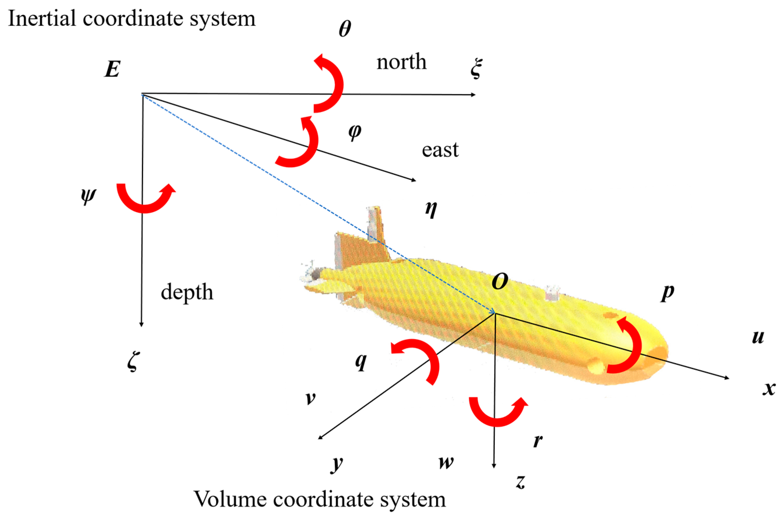
To provide a unified and precise approach for describing, locating, measuring, and analyzing geometric elements such as the UUV’s pose in three-dimensional space, as well as its relative position to the moving mother ship, it is necessary to establish a systematic coordinate framework comprising an Earth-fixed coordinate system (E-ξηζ) and a body-fixed coordinate system (O-xyz). As shown in Figure 2:
In the defined coordinate systems: x, y, z represents the longitudinal, lateral, and vertical axes of the UUV body frame, respectively; ξ, η, ζ denotes the east, north, and depth directions in the Earth-fixed frame; φ, θ, ψ correspond to the UUV’s roll, pitch, and yaw angles; u, v, w indicate the linear velocities in surge, sway, and heave directions; p, q, r represent the angular velocities in roll, pitch, and yaw, respectively. All subsequent analyses in this paper adhere to these coordinate conventions.

2.2. Settlement-Based Recovery Strategy and Control Framework

To meet the requirements of UUV’s seated docking, a segmented recovery strategy is designed.
  • Stage 1: Long-distance tracking stage
Control is performed based on the deviation information between the UUV and the mother platform provided by acoustic guidance, enabling the UUV to gradually approach the area above the mother platform. This stage continues until the optical guidance camera mounted on the UUV can recognize the light array on the back of the mother platform and provide deviation information with sufficient confidence, after which the second stage is initiated.
  • Stage 2: Short-distance docking stage
Seated docking control is implemented using the deviation information between the UUV and the mother platform, which is provided by either optical guidance or the fusion of acoustic-optical guidance. This stage proceeds until the UUV fully enters the docking device.
The specific process is shown in the following Figure 3:
Tracking Phase for Long Distance: The primary design strategy during this stage is to enable the UUV to rapidly approach a position slightly above and oblique to the moving mother platform. This phase has relatively lower requirements for control precision, as it only necessitates that the camera can identify the guidance light array to enhance the overall efficiency of the recovery process.
Docking Phase for Short Distance: Through extensive experimental studies have revealed that when this class of mothership employs buoyancy control systems for depth regulation, significant depth oscillations occur due to the minimal effectiveness of the vertical tunnel thrusters on large mobile motherships coupled with the inherently low precision of buoyancy-based depth control. To accommodate this phenomenon and prevent excessive impact on the docking device during UUV descent, a phased descent strategy was designed. Specifically, when the relative depth between the mother platform and the UUV falls within a certain range, the UUV hovers at its current depth and waits. Using guidance information, it determines whether the mothership is in an ascending or descending phase. If the mothership is descending, the UUV adjusts its depth downward accordingly. If the mothership is ascending, the UUV continues to hover and wait. Once the relative depth between the two is reduced below a certain threshold, a “press-down” control is executed, ultimately ensuring the docking rod fully enters the docking device, thereby completing the recovery and docking mission.
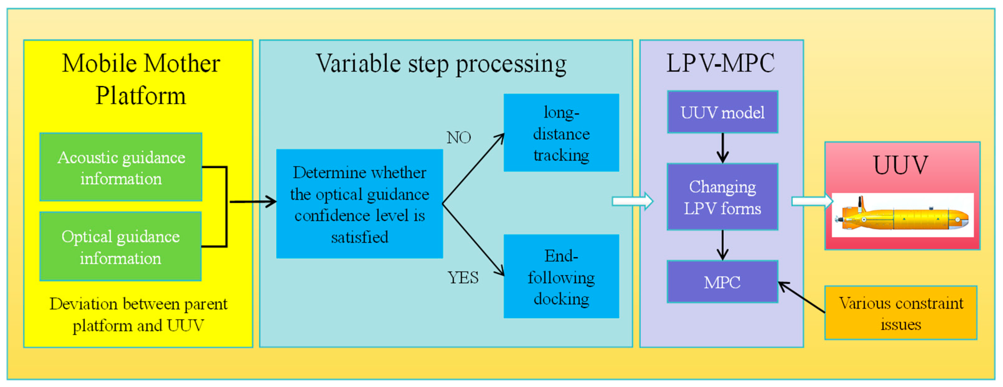
To implement the aforementioned recovery process, the overall control block diagram designed in this study is presented below. As shown in Figure 4. First, the original UUV model is processed and transformed into a Linear Parameter-Varying (LPV) system representation. Constraints are incorporated, and a Model Predictive Control (MPC) controller is designed. Subsequently, based on the confidence level of the optical guidance information, the recovery phase of the UUV is determined, and the prediction horizon is adjusted to improve controller efficiency. Finally, the controller output is transmitted to the UUV to complete the control loop.

2.3. Modeling of the UUV

The dynamic and kinematic models of conventional UUVs and their mother platforms (large UUVs) have been extensively modeled in numerous references [19,20]. Here, only a simplified formulation is provided without further elaboration.
Kinematic model:
η ˙ i = J η V i J = cos ψ cos θ sin ψ sin θ cos ψ 0 0 0 sin ψ cos θ cos ψ sin θ sin ψ 0 0 0 sin θ 0 cos θ 0 0 0 0 0 0 1 0 tan θ 0 0 0 0 1 0 0 0 0 0 0 1 / cos θ
Dynamic model:
M i V ˙ i + C i V i V i + D i V i V i + g i η i = τ + Ω i M = m X u ˙ 0 0 0 0 0 0 m Y v ˙ 0 0 0 0 0 0 m Z w ˙ 0 0 0 0 0 0 I x K p ˙ 0 0 0 0 0 0 I y M q ˙ 0 0 0 0 0 0 I z N r ˙ C = 0 0 0 0 m w Z w ˙ w m v + Y v ˙ v 0 0 0 m w + Z w ˙ w 0 m u X u ˙ u 0 0 0 m v Y v ˙ v m u + X u ˙ u 0 0 m w Z w ˙ w m v + Y v ˙ v 0 I z r N r ˙ r I y q + M q ˙ q m w + Z w ˙ w 0 m u X u ˙ u I z r + N r ˙ r 0 I x p K p ˙ p m v Y v ˙ v m u + X u ˙ u 0 I y q M q ˙ q I x p + K p ˙ p 0 D = d i a g X u , Y v , Z w , K p , M q , N r d i a g X u u u , Y v v v , Z w w w , K p p p , M q q q , N r r r g = 0 0 0 ρ g V G M L ¯ cos θ sin φ ρ g V G M L ¯ sin θ 0
In the formula, i = 1, 2 represent the UUV and the mother platform, η ˙ i = [ x ˙ i , y ˙ i , z ˙ i , ϕ ˙ i , θ ˙ i , ψ ˙ i ] i , V i = [ u i , v i , w i , p i , q i , r i ] , Mi, Ci, and Di are inertia mass, centripetal force, and damping matrices containing hydrodynamic parameters, respectively, and J is the transformation matrix between the earth-fixed frame and the body-fixed frame, τ denote the control force and Ω i represent external disturbances. For the controller design presented in this paper, the physical quantities in the matrix can be treated as constants. Therefore, the specific physical significance of individual parameters within the matrix will not be elaborated here. For details, refer to [21,22].
To investigate MPC, researchers typically reformulate the UUV model into the following linear time-varying form:
χ ˙ ( t ) = A χ ( t ) + B U ( t ) Y ( t ) = c χ ( t )
where the state vector is: χ = [ u , v , w , p , q , r , ξ , η , ζ , ϕ , θ , φ ] T , the control input is: U = [ τ u , τ v , τ w , τ p , τ q , τ r ] T and the output is: Y = [ ξ , η , ζ , ϕ , θ , φ ] T . Therefore, the matrices in the above equations can be derived from Equations (1) and (2):
A = M 1 C M 1 D 0 6 × 6 J 0 6 × 6
B = M 1 0 6 × 6
c = 0 6 × 6 I 6 × 6
Substituting Equations (4)–(6) into Equation (3) yields a preliminary UUV dynamic and kinematic model. However, it can be observed that the resulting model still contains unexpressed nonlinear terms (this issue will be specifically addressed in Section 3).
However, the thrust of each thruster cannot directly represent the forces acting on each degree of freedom in the model. Therefore, the controller outputs need to be properly allocated to the thrusters based on their installation positions [23].
As shown in Figure 5, T1 and T2 represent the two horizontal main thrusters of the UUV, T3 and T4 represent the stern vertical tunnel thruster and the bow vertical tunnel thruster, respectively, and T5 and T6 represent the stern horizontal tunnel thruster and the bow horizontal tunnel thruster, respectively. L1 and L2 represent the distances from the bow and stern vertical tunnel thrusters to the center of gravity of the UUV, respectively, while L3 and L4 represent the distances from the stern and bow horizontal tunnel thrusters to the center of gravity of the UUV, respectively.
Based on the position information of the above-mentioned thrusters, the following thrust allocation formulas can be obtained:
T 1 + T 2 = τ u T 3 + T 4 = τ z T 5 + T 6 = τ v T 4 × L 1 T 3 × L 2 = τ q T 6 × L 4 T 5 × L 3 = τ r
The required control forces to be allocated to each thruster can be obtained as follows:
T 1 = 1 2 τ u T 2 = 1 2 τ u T 3 = L 1 τ z τ q L 1 + L 2 T 4 = L 2 τ z + τ q L 1 + L 2 T 5 = L 4 τ v τ r L 3 + L 4 T 6 = L 3 τ v + τ r L 3 + L 4
Furthermore, in practical applications, the control input U requires a transmission process to act on the actuators, as illustrated in Figure 6. Therefore, this factor must be considered in model construction.
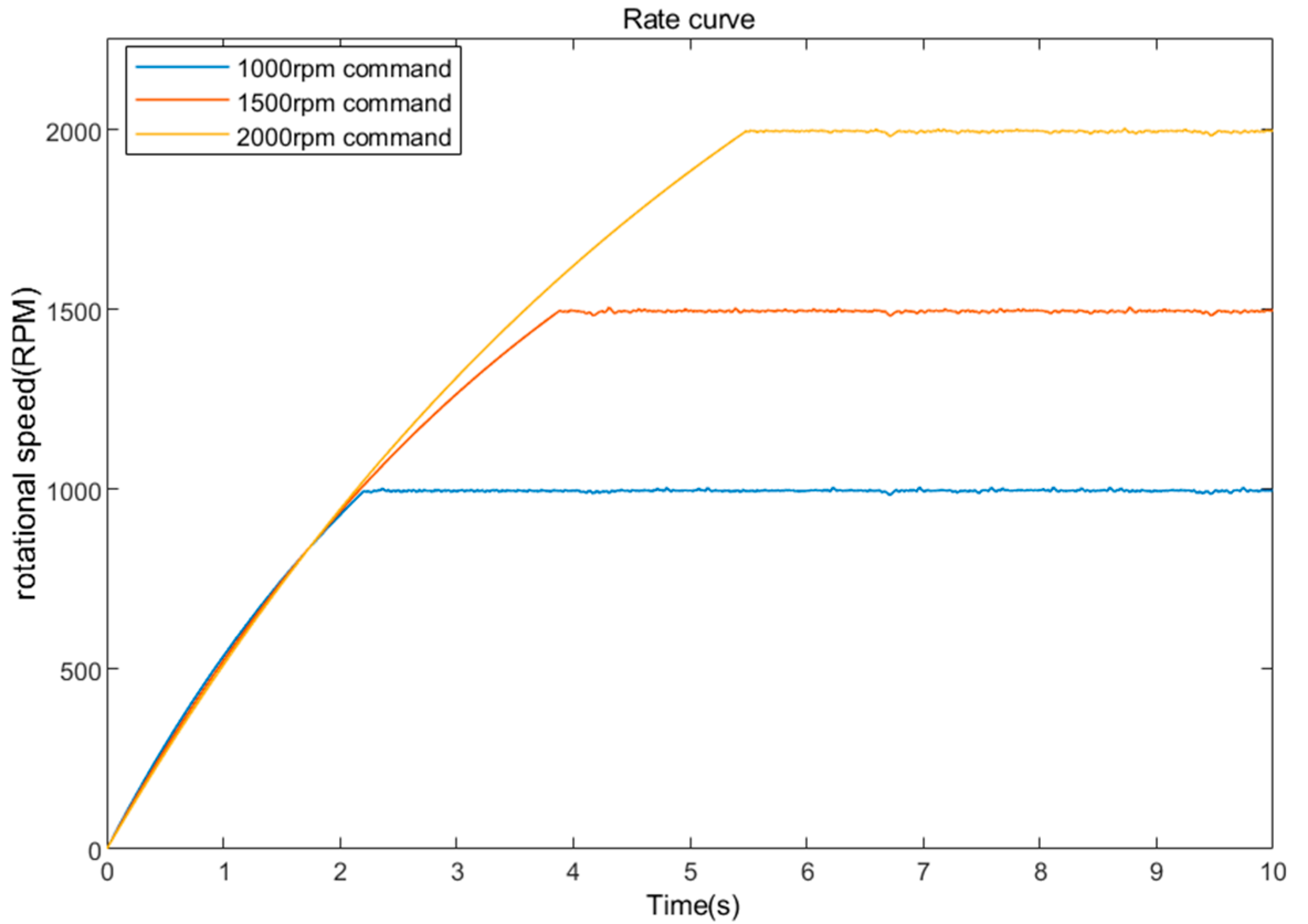
Figure 7 presents the rotational speed response curves provided by the thruster manufacturer for each propeller at 500 rpm, 1000 rpm, and 2000 rpm. Based on these curves, we model the transmission process as a second-order linear system, The corresponding transfer function can be obtained using the System Identification Toolbox in MATLAB2024b, expressed as:
G propeller ( s ) = 0.56 s 2 + 1.14 s + 0.57
In the equation, the input represents the desired rotational speed, while the output corresponds to the actual real-time rotational speed. Therefore, we obtain:
n ¨ r ( t ) = 1.14 n ˙ r ( t ) 0.57 n r ( t ) + 0.56 n c ( t )
where n c ( t ) is the converted rotational speed of the controller output, n r ( t ) is the actual rotational speed applied to the thruster. Since thrust is positively correlated with rotational speed, the complete UUV docking control model can be derived by combining the corresponding thrust–speed relationship with Equations (3) and (7)–(10).

3. Quasi-LPV Modeling of UUV Dynamics

To investigate the design of the UUV docking controller in this study, this chapter presents a quasi-linear parameter-varying (quasi-LPV) system representation of the nonlinear UUV dynamic model, along with the corresponding transformation method.
Unlike conventional LPV systems where parameters are independent external variables, the quasi-LPV system allows parameters to incorporate the system’s states or input variables, which are coupled with the internal dynamics. This characteristic makes quasi-LPV systems more flexible in practical applications.
According to Reference [24], the state–space representation of the quasi-LPV system can be derived as follows:
χ ˙ ( t ) = A ( p ( t ) ) χ ( t ) + B ( p ( t ) ) U ( t ) Y ( t ) = c ( p ( t ) ) χ ( t )
According to Reference [25], the state–space matrices A, B, and c are functions of the time-varying parameter p(t) (Since all state variables of the UUV are time-varying, they are selected as time-dependent parameters p(t) that evolve with time). This LPV system can be regarded as a linearized representation of the UUV nonlinear model along the trajectory of p(t). In Equation (11), the varying parameter p(t) can be either an externally defined parameter or a state variable of the UUV system itself, such as u, v, w, p, q, or r.
Currently, three commonly used methods exist for converting nonlinear model systems into LPV forms [26,27,28]: Jacobian linearization, state transformation, and function substitution. The Jacobian linearization method exhibits low efficiency in LPV modeling due to its reliance on continuous interpolation, while the state transformation method imposes strict constraints on system forms and is thus unsuitable for UUV docking systems. Therefore, this paper presents an improved function substitution method to convert the UUV dynamic model into a QLPV form (the conversion approach for the kinematic model is identical to that of the dynamic model and will not be elaborated on herein).
According to Equation (2), the dynamic equation of the UUV can be derived, which contains other nonlinear terms (g matrix). In previous studies, the positions of the center of gravity and the center of buoyancy in the g matrix are generally treated as coincident, and the buoyancy force is directly omitted. If Equation (3) is directly converted using this method, it will lead to a large discrepancy between the model and the actual situation.
Here, Equation (3) is first rewritten into the following form:
χ ˙ ( t ) = f ( χ ( t ) , u ( t ) ) Y ( t ) = c χ ( t )
In Equation (12), f : ( R n , R m ) R n are the nonlinear functions of the system.
Here, it is assumed that all state variables of the system are listed as varying parameter state variables; thus, the conversion of the system shown in the upper portion of Equation (12) yields:
χ ˙ = f χ ( χ ) χ + Q ( χ ) u + N χ ( χ )
In Equation (13), f χ is a function of variables with varying parameters. Decomposing the nonlinear term N χ in the equation yields:
N χ ( χ ) = n χ ( χ ) χ
In the formulation, n χ ( χ ) is equivalent to introducing a state variable χ into N χ where χ was originally not contained. Moreover, since the state variables of the UUV are selected as time-varying parameters p(t), functions of χ ( t ) are equivalent to functions of p(t). Substituting Equation (14) into the upper portion of Equation (12) yields the quasi-LPV expression form of the UUV system:
χ ˙ = [ f χ ( χ ) + n χ ( χ ) ] χ + Q ( χ ) u
In the LPV system satisfying Equation (11):
A ( p ( t ) ) = f χ ( χ ( t ) ) + n χ ( χ ( t ) ) B ( p ( t ) ) = Q χ ( χ ( t ) ) c χ ( t ) = c ( p ( t ) )
Next, based on the UUV nonlinear model presented in Section 2.3, an expansion process is performed. By substituting M, C, D, and some parameter expressions containing hydrodynamic coefficients into the UUV model, the sorted dynamic model can be obtained as:
u ˙ = m Z w ˙ w q m + Y v ˙ v r + X u + X u u u u ( W F B ) sin θ + τ u m X u ˙ v ˙ = m X u ˙ u r + Y v + Y v v v v + τ v m Y v ˙ w ˙ = m + X u ˙ u q + Z w + Z w w w w + ( W F B ) cos θ + τ w m Z w ˙ q ˙ = m + Z w ˙ w u m X u ˙ u w + M q + M q q q q ρ g V G M L ¯ sin θ + τ q I y M q ˙ r ˙ = m Y v ˙ v u m + X u ˙ u v + N r + N r r r r + τ r I z N r ˙
Since most UUVs have a symmetrical shape and a relatively high metacentric height, the roll degree of freedom is not considered here.
In practice, the velocity information and partial pose information of the UUV can be obtained using sensors such as GPS, inertial navigation systems (INS), and Doppler Velocity Logs (DVL). Therefore, the velocity components of each degree of freedom u, v, w, p, q, and r are selected as the variable parameters, and Equation (15) is transformed into the following form:
u ˙ v ˙ w ˙ q ˙ r ˙ = X u + X u u u m X u ˙ 0 0 m Z w ˙ w m X u ˙ m + Y v ˙ v m X u ˙ 0 Y v + Y v v v m Y v ˙ 0 0 m X u ˙ u m Y v ˙ 0 0 Z w + Z w w w m Z w ˙ m + X u ˙ u m Z w ˙ 0 m + Z w ˙ w I y M q ˙ 0 m X u ˙ u I y M q ˙ M q + M q q q I y M q ˙ 0 m Y v ˙ v I z N r ˙ m + X u ˙ u I z N r ˙ 0 0 N r + N r r r I z N r ˙ u v w q r + 1 m X u ˙ 0 0 0 0 0 1 m Y v ˙ 0 0 0 0 0 1 m Z w ˙ 0 0 0 0 0 1 I y M q ˙ 0 0 0 0 0 1 I z N r ˙ τ u τ v τ w τ q τ r + ( W F B ) sin θ m X u ˙ 0 ( W F B ) cos θ m Z w ˙ ρ g V G M L ¯ sin θ I y M q ˙ 0
Here, following the approach of Equations (14) and (15), equating the nonlinear term N χ in the equation to N χ = n χ ( χ ) u is equivalent to introducing a system variable parameter u into N χ , which does not originally include system parameters. The nonlinear terms in Equation (18) are reformulated into the following form:
( W F B ) sin θ m X u ˙ 0 ( W F B ) cos θ m Z w ˙ ρ g V G M L ¯ sin θ I y M q ˙ 0 = ( W F B ) sin θ m X u ˙ u 0 ( W F B ) cos θ m Z w ˙ u ρ g V G M L ¯ sin θ I y M q ˙ u 0 0 4 × 5 u v w q r
Thus, the nonlinear part can be incorporated into matrix A ( p ( t ) ) . Here, let:
1 m X u ˙ = d 11 , 1 m Y v ˙ = d 22 , 1 m Z w ˙ = d 33 , 1 I y M q ˙ = d 44 , 1 I z N r ˙ = d 55
By substituting Equations (19) and (20) into Equation (18), the quasi-LPV form of the UUV system can be obtained as follows:
u ˙ v ˙ w ˙ q ˙ r ˙ = X u + X u u u ( W F B ) sin θ u d 11 0 0 m Z w ˙ w d 11 m + Y v ˙ v d 11 0 Y v + Y v v v d 22 0 0 m X u ˙ u d 22 ( W F B ) cos θ u d 33 0 Z w + Z w w w d 33 m + X u ˙ u d 33 0 m + Z w ˙ w d 44 0 m X u ˙ u d 44 M q + M q q q d 44 0 m Y v ˙ v ρ g V G M L ¯ sin θ u d 55 m + X u ˙ u d 55 0 0 N r + N r r r d 55 u v w q r + d 11 0 0 0 0 0 d 22 0 0 0 0 0 d 33 0 0 0 0 0 d 44 0 0 0 0 0 d 55 τ u τ v τ w τ q τ r
It can be observed that this method imposes no requirements on the selection of equilibrium points and avoids complex operations involving remainders with variable parameters.
The proposed approach transforms the original nonlinear model into a parameter-dependent linear model, where the nonlinear dynamics are implicitly embedded in the parameter variations. Although the system remains inherently nonlinear, its linear structure in form facilitates controller design and analysis using linear control theory.

4. Design of a Piecewise Variable-Step-Size MPC Controller for QLPV Systems

This chapter focuses on two distinct phases during the recovery and docking process between the UUV and its mobile mother ship. Based on the quasi-LPV representation of the UUV dynamic model derived in the previous chapter, a variable-step model predictive controller (MPC) is designed.

4.1. Long-Range Tracking Phase

Since the long-distance tracking phase requires the UUV to catch up with the moving mother ship from a distance, the UUV’s navigation speed must be higher than that in the close-range following and docking phase. At higher speeds, the UUV needs a longer prediction horizon to avoid potential hazardous situations. However, increasing the prediction horizon while still using the traditional zero-order hold (ZOH) method for discretization would result in the control input being unable to adjust over the extended horizon, leading to a mismatch between the control input and the model’s requirements.
The long-distance tracking phase relies on acoustic guidance, and the propagation speed of acoustic signals is relatively low. Therefore, a longer discretization step can be adopted based on practical conditions.
First, the first-order hold (FOH) discretization method is employed to discretize the UUV dynamic model, yielding:
χ ˙ l ( k ) u ˙ l ( k ) t l u ¨ l ( k ) = A l B l 0 0 0 I t l 0 0 0 χ l ( k ) u l ( k ) t l u ˙ l ( k )
χ l ( k + 1 ) u l ( k + 1 ) t l u ˙ l ( k + 1 ) = A P l B P l 1 B P l 2 0 I I 0 0 I χ l ( k ) u l ( k ) t l u ˙ l ( k )
In the equation, the subscript l denotes variables in the long-range tracking phase, and I n R χ represents an n-th order identity matrix. Here, A P l = I 5 + t l A l + ( t l A l ) 2 2 , B P l 1 = t l B l + t l 2 A l B l 2 , and B P l 2 = t l B l 2 represent the discretized system matrices, tl denotes the prediction step length in the long-range tracking phase, and u remains constant within tl.
Therefore, combining the quasi-linear parameter-varying (QLPV) system model of the UUV derived in the previous section, we obtain:
χ l ( k + 1 ) = A P l ( p ( k ) ) χ l ( k ) + ( B P l 1 B P l 2 ) ( p ( k ) ) u l ( k ) + B P l 2 ( p ( k ) ) u l ( k + 1 ) Y l ( k ) = c P l ( p ( k ) ) χ l ( k )
Subsequently, the system states can be predicted according to Equation (24), yielding:
χ l ( k + 1 ) χ l ( k ) = A P l ( p ( k ) ) ( χ l ( k ) χ l ( k 1 ) ) + ( B P l 1 B P l 2 ) ( p ( k ) ) ( u l ( k ) u l ( k 1 ) ) + B P l 2 ( p ( k ) ) ( u l ( k + 1 ) u l ( k ) )
Y l ( k ) Y l ( k 1 ) = c P l ( p ( k ) ) ( χ l ( k ) χ l ( k 1 ) )
Here, we construct a bias model. First, let:
χ e l ( k ) = χ l ( k ) χ l ( k 1 ) χ e l ( k + 1 ) = χ l ( k + 1 ) χ l ( k ) u e l ( k ) = u l ( k ) u l ( k 1 ) Y e l ( k ) = Y l ( k ) Y l ( k 1 )
where
χ e l ( k ) = u ¯ l ( k ) u ¯ l ( k 1 ) v l ( k ) v l ( k 1 ) φ l ( k ) φ l ( k 1 ) , u e l ( k ) = τ u l ( k ) τ u l ( k 1 ) τ v l ( k ) τ v l ( k 1 ) τ r l ( k ) τ r l ( k 1 )
To distinguish between the control input and the longitudinal velocity of the hull, the longitudinal velocity is denoted by u ¯ l .
Therefore, Equation (26) can be rewritten as:
Y e l ( k ) = c P l ( p ( k ) ) χ e l ( k )
Finally, the deviation state–space equation can be obtained as:
χ e l ( k + 1 ) = A P l ( p ( k ) ) χ e l ( k ) + ( B P l 1 B P l 2 ) ( p ( k ) ) u e l ( k ) + B P l 2 ( p ( k ) ) u e l ( k + 1 ) Y e l ( k ) = c P l ( p ( k ) ) χ e l ( k )
From Equation (30), it can be observed that the deviation state variables depend not only on u(k) but also on u(k + 1). Therefore, the prediction equation in Reference [29] needs to be rewritten in the following matrix form:
Y e l ( k ) = c P l ( p ( k ) ) χ e l ( k )
In the equation, Y e l = [ Y e l ( k + 1 ) , Y e l ( k + 2 ) , , Y e l ( k + N p ) ] T represents the output after the prediction horizon Np, F l = [ C p l A p l , C p l A p l 2 , , C p l A p l N p ] T and U 0 = [ u e l ( k ) , u e l ( k + 1 ) , , u e l ( k + N c 1 ) ] T denote the inputs from the current step to Nc−1, U 1 = [ u e l ( k + 1 ) , u e l ( k + 2 ) , , u e l ( k + N c ) ] T corresponds to the future Nc step inputs, and Φ 0 , Φ 1 is the Toeplitz matrix composed of A P l , B P l 1 , B P l 2 , which will not be elaborated here.
Next, we analyze the potential constraints for long-distance tracking. When the UUV operates at a considerable distance from the mother ship, the main constraints to be considered include:
(1)
Thruster Thrust Saturation Constraint:
Since each thruster has a maximum rotation speed limit, the maximum force output of each thruster must be considered. Therefore, the thrust constraint for each actuator should be set as follows:
τ max < T < τ max
Therefore, from Equation (32), we obtain:
u min ε l < U 0 < u max + ε l
u min ε l < U 1 < u max + ε l
where ε l is the relaxation factor introduced in this stage to address the issue of being unable to obtain the optimal solution within the specified time due to the model’s complexity.
Moreover, since the input constraints must simultaneously apply to both U0 and U1, (U0 represents the control input at the current time step) and U1 is a shifted version of U0, we design a shift matrix S to simplify Equations (33) and (34) into constraints on U0 only, i.e.,
U 1 = S U 0
(2)
UUV Depth Constraint:
Since the acoustic ultra-short baseline (USBL) system is installed on the underside of the UUV, while the transponder is mounted on the upper side of the moving mother platform and can only receive signals from below, the UUV must always maintain a depth above the mother platform. Therefore, the depth constraint is set as follows:
z 1 < z 2
(3)
Mission Time Constraint:
Due to stealth requirements of the mobile platform, it cannot maintain a low-speed hovering state for an extended period while waiting for UUV docking and recovery. Therefore, the UUV recovery mission must be time-constrained, with the following time limitation imposed:
t < t max
According to the above analysis, the performance indices required for tracking the moving target and controlling the variation in the control input are designed as follows:
J l = ( Y e R l ) T ( Y e R l ) + Δ U l T r w l Δ U l + ρ l ε l 2
where
R l = F l Y d
The above equation represents the desired output matching the predicted output, where Yd is the pose of the mobile mother platform, and rw is a user-defined weight matrix, ε l is the relaxation factor for this stage, while ρ l denotes the correlation coefficient of the relaxation factor.
Since the variation in the performance index depends only on the change rate of the control input Δ U l , the control problem at each prediction horizon can be further transformed into the following optimization problem:
min J l = Δ U l T [ ( Φ 0 + Φ 1 S ) T ( Φ 0 + Φ 1 S ) + r w ] Δ U l + 2 ( Φ 0 + Φ 1 S ) T F l ( χ e Y d ) + ρ l ε l 2 s . t . ( 33 ) ( 34 ) ( 36 ) ( 37 )
After invoking the relevant solver to obtain the required Δ U l , it is added to the control input from the previous step and then substituted into the controller output. This resulting control signal is applied to the UUV dynamic model, enabling the real-time computation of the UUV’s evolving pose state. That is,
u l ( t ) = u l ( t 1 ) + Δ U l
Then, based on the characteristics of model predictive control (MPC), the prediction and optimization steps are iteratively performed in sequence, thereby accomplishing the control objectives for this phase.

4.2. Close-Range Docking Phase

During the close-range docking phase, the UUV’s position and attitude must precisely follow those of the moving mother ship. Therefore, the control accuracy of the UUV needs to be higher than in the long-range tracking phase. Additionally, since the UUV’s speed only needs to match that of the mother ship and is relatively low, a shorter prediction horizon can be adopted in this phase.
The close-range docking phase is conducted using optical guidance. Given that optical signals propagate much faster than acoustic signals, a shorter discretization step can be employed here, depending on the actual conditions, to improve control accuracy.
First, the zero-order hold (ZOH) discretization method is applied to discretize the UUV dynamic model, yielding:
χ ˙ s ( k ) u ˙ s ( k ) = A s B s 0 0 χ s ( k ) u s ( k )
χ s ( k + 1 ) u s ( k + 1 ) = A P s A P s 0 I χ s ( k ) u s ( k )
In the equation, the subscript s denotes variables in the close-range docking phase, I n R is an n-th order identity matrix, A P l = I 5 + t s A s and B P s = t s B s are the corresponding matrices after system discretization, and ts is the prediction step length during the close-range docking phase, where u remains constant within ts.
Therefore, by combining the quasi-linear parameter-varying (QLPV) system model of the UUV derived in the previous chapter, we obtain:
χ s ( k + 1 ) = A P s ( p ( k ) ) χ s ( k ) + B p s ( p ( k ) ) u s ( k ) Y s ( k ) = c P s ( p ( k ) ) χ s ( k )
The derivation process of the error model here follows the same procedure as from Equation (25) to Equation (29). For brevity, we omit the repetitive details and directly present the error model for this phase as:
χ e s ( k + 1 ) = A P s ( p ( k ) ) χ e s ( k ) + B P s ( p ( k ) ) u e s ( k ) Y e s ( k ) = c P s ( p ( k ) ) χ e s ( k )
Consequently, the matrix form of the output prediction equation for this phase can be expressed as:
Y e s = F s χ e s ( k ) + Φ s U s
In the equation, Y e s = [ Y e s ( k + 1 ) , Y e s ( k + 2 ) , , Y e s ( k + N p ) ] T represents the output after the prediction horizon Np, while F s = [ C p s A p s , C p s A p s 2 , , C p s A p s N p ] T and U s = [ u e s ( k ) , u e s ( k + 1 ) , , u e s ( k + N c 1 ) ] T denote the inputs from the current step to step Nc−1. Φ s is a Toeplitz matrix composed of A P s , B P s , the detailed formulation of which is omitted here for brevity.
Subsequently, we analyze potential constraints during close-range docking. In addition to the constraints present in the long-range tracking phase, the following primary constraints must be considered when the UUV approaches the mother ship:
(1)
Sensor observation constraints:
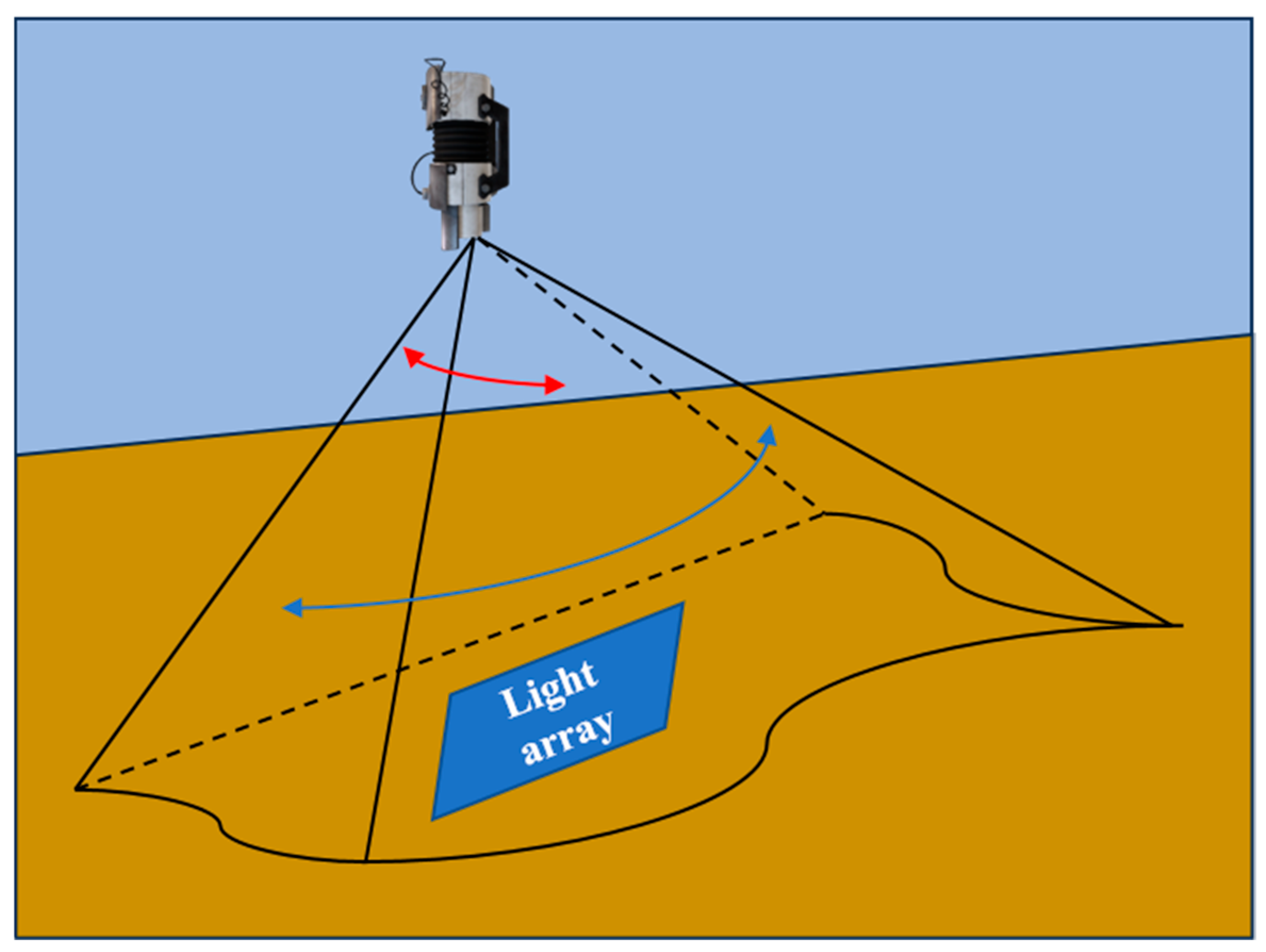
As shown in Figure 8, the optical camera is installed on the ventral side of the UUV, while the light array is mounted on the dorsal side of the mobile mother platform.
Therefore, it is necessary to impose certain restrictions on the UUV’s attitude based on the opening angle range recognizable by the camera, ensuring that the installed optical beacon remains within the observation range of the UUV’s guidance sensor throughout the process of descending into the docking device. The UUV’s attitude constraints should be set as follows:
ψ e < ψ e max
θ max < θ < θ max
(2)
Geometric Constraints:
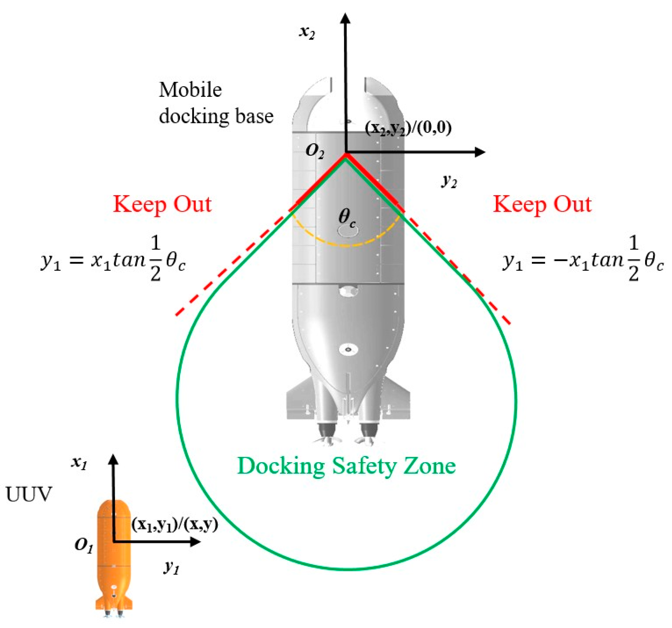
Considering the potential collision between the UUV and the moving mothership during the final docking phase, particularly in the docking process with medium/large-sized motherships, as illustrated in Figure 9:
In the figure, θc represents the opening angle range of the docking fork, where the subscript 1 denotes the UUV and the subscript 2 denotes the moving mothership. The coordinates of the UUV in the mothership’s coordinate system are (x1, y1). Therefore, the UUV’s navigation trajectory must be confined within a geometric region relative to the mothership to avoid collisions with the mothership’s stern thrusters, propellers, rudders, hull, and antennas. The UUV’s position constraints should be set as follows:
x 1 < 0 x 1 tan 1 2 θ c < y 1 < x 1 tan 1 2 θ c
Moreover, in practical scenarios, the guidance beacon provides the relative pose deviation between the two entities with respect to the UUV as the origin. Therefore, Equation (50) needs to be rewritten in the following form:
x < x 2 ( x x 2 ) tan 1 2 θ c < y y 2 < ( x x 2 ) tan 1 2 θ c
Based on the above analysis, the performance indices required for docking with a moving target and control input variation are designed as follows:
J s = ( Y e R s ) T ( Y e R s ) + Δ U s T r w s Δ U s + ρ s ε s 2
where
R s = F s Y d
The variables in the equation have the same meanings as those in the previous section. Therefore, the problem can be transformed into the following optimization formulation:
min J l = Δ U s T ( Φ s T Φ s + r w ) Δ U s + 2 Φ s T F s ( χ e Y d ) + ρ s ε s 2 s . t . ( 33 ) ( 34 ) ( 36 ) ( 37 ) ( 48 ) ( 49 ) ( 51 )
After invoking the relevant solver to obtain the required Δ U s , it is added to the control input from the previous step and then substituted into the controller output. This resulting control signal is applied to the UUV dynamic model, enabling the real-time computation of the UUV’s evolving pose state. That is:
u s ( t ) = u s ( t 1 ) + Δ U s
Then, based on the characteristics of model predictive control (MPC), the prediction and optimization steps are iteratively performed in sequence, thereby accomplishing the control objectives for this phase.

5. Simulations and Experiments

5.1. Simulation Analysis

The moving-base docking system and controller developed in this study were designed based on a peg-in-hole recovery strategy for UUVs. To evaluate the feasibility of this strategy and the control performance, systematic simulation analyses were conducted. The hydrodynamic parameters of the UUV were calculated by another research team, while Table 1 presents some fundamental parameters of the UUV.
In the table, m represents the UUV mass, I denotes the correlation coefficients of rotational inertia, X u ˙ , Y v ˙ , Z w ˙ and X u , Y v , Z w are the primary hydrodynamic coefficients, FB is the positive buoyancy, and GML stands for the metacentric height.
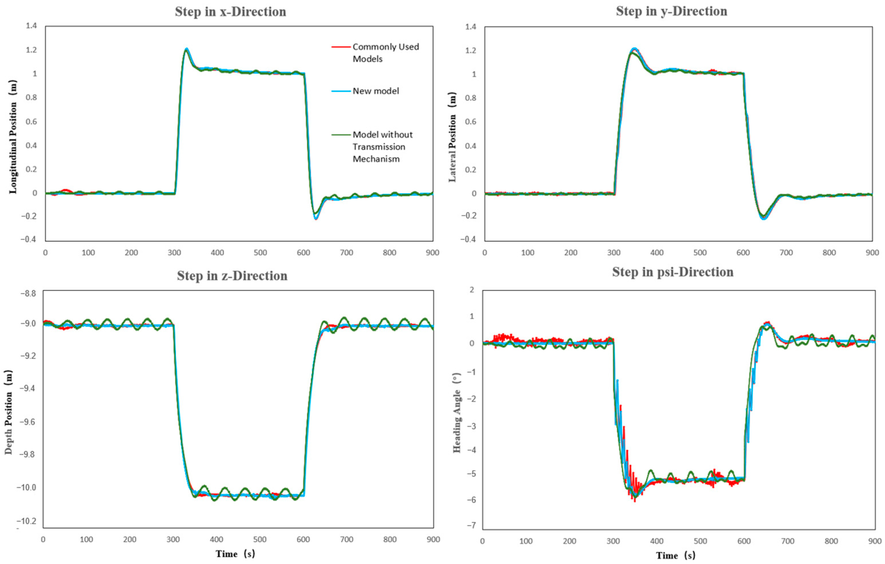
First, in order to illustrate the differences between the UUV model designed in Section 2 and Section 3 of this paper and the commonly used UUV models, the UUV is subjected to a four-degree-of-freedom step motion in three-dimensional space. A PID controller with the same parameters is used to control the relevant models, and the effects are observed and compared. It is assumed that the initial position (x, y, z) of the UUV is (0 m, 0 m, −9 m), and the initial attitudes (roll angle, pitch angle, heading angle) are (0°, 0°, 0°). As shown in Figure 10:
The following also presents the variation in roll and pitch angles for different models under the same controller when the desired six-degree-of-freedom positions are all 0 (m/°). As shown in Figure 11:
Results indicate that under the same controller, the control performance varies significantly across different models, particularly in attitude angle regulation. This demonstrates that improving model accuracy is essential for effective UUV control.
Next, the effectiveness of the proposed controller and the feasibility of the docking procedure will be examined. The UUV starts from rest at an initial position of (0 m, 0 m, −6 m) in the North–East–Down (NED) coordinate system to track a moving mother ship. A phased control strategy, as designed in Section 2.2, is implemented, with the close-range docking phase initiated once the longitudinal and lateral deviations fall below predefined thresholds. The mother ship’s initial position at the start of the docking mission is assumed to be (5 m, 5 m, −13 m) in the NED frame. Its longitudinal, lateral, depth, and heading motions are prescribed by the following time-dependent functions:
x 2 = ( 5 0.000006 t 2 0.0082 t ) ( m ) y 2 = ( 5 0.000006 t 2 0.0082 t ) ( m ) z 2 = ( 12 + s i n 0.008 t + 300 ) ( m ) ψ 2 = 0.23 t ( ° )
To enable the UUV to track and dock with a moving base, it is necessary to ensure that the degree-of-freedom deviations between the UUV and the moving base are ideally zero. In practice, the control performance improves as these deviations approach zero. In this study, the discrete step size for the UUV model is set to 0.25 during the long-range tracking phase and 0.1 during the close-range docking phase (The selection of the discrete step size is determined by the transmission frequency of the actual sensor), with a total process time of 1200 s. Other constraint values and some controller parameters designed in this work are as follows:
N p = 30 N c = 4 r w = 0.0007 ρ = 0.01 t max = 1500 s τ max = 600 N p s i max = 5 ° p h i max = 5 ° θ c = 90 °
Below, we conduct full-process simulations of the UUV’s dynamic base docking operation under a PID controller, a traditional MPC controller, and the proposed controller (QLPV-MPC). To more clearly demonstrate the differences between these controllers, a 0.5-knot downstream ocean current disturbance is introduced during the simulation.
The structure of the PID controller primarily comprises:
(1)
Input: The deviation between the system output and the desired setpoint;
(2)
Core Algorithm: Proportional, integral, and derivative operations applied to the error, followed by a weighted summation of the results;
(3)
Output: The computed control signal.
Parameters of the six-degree-of-freedom (6-DoF) PID controller are configured as follows:
x : P = 80 , I = 0.001 , D = 4000 y : P = 180 , I = 0.001 , D = 2000 z : P = 100 , I = 0.001 , D = 10000 θ : P = 100000 , I = 8 , D = 800000 ψ : P = 100000 , I = 4.5 , D = 800000
The structure of the MPC controller primarily comprises:
(1)
Input: The current state of the system;
(2)
Core Algorithm: Utilizing an internal predictive model to forecast system behavior over a finite horizon, solving an optimization problem to identify a sequence of future control actions that minimize the objective function, applying only the first control action in the sequence, and repeating the entire process at the next time step (receding horizon optimization);
(3)
Output: The optimized control signal computed.
The distinction between the conventional MPC and the proposed MPC primarily lies in model enhancements and the adaptive adjustment of step size across phases. Other control parameters of the conventional MPC remain consistent with those in Equation (56).
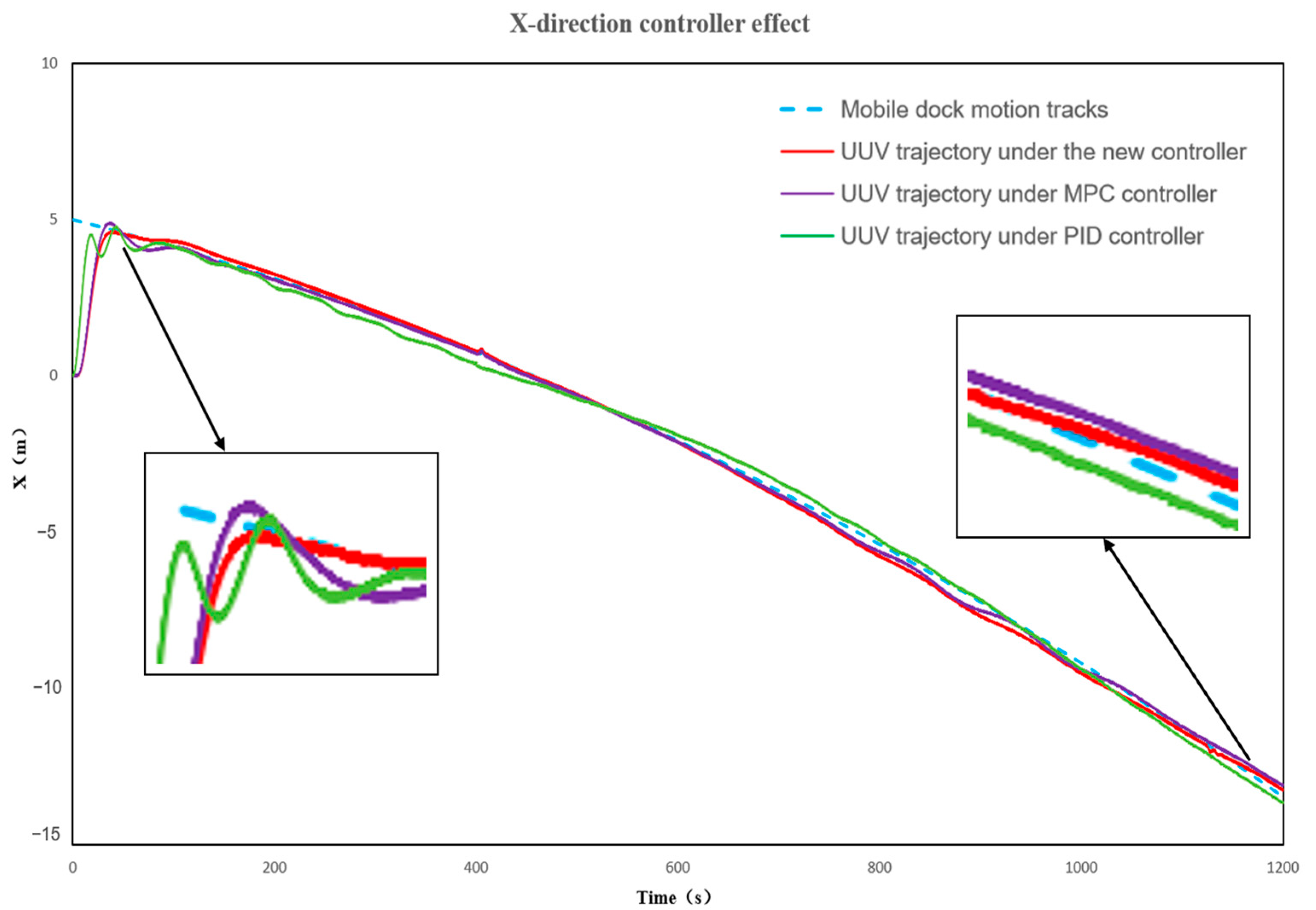
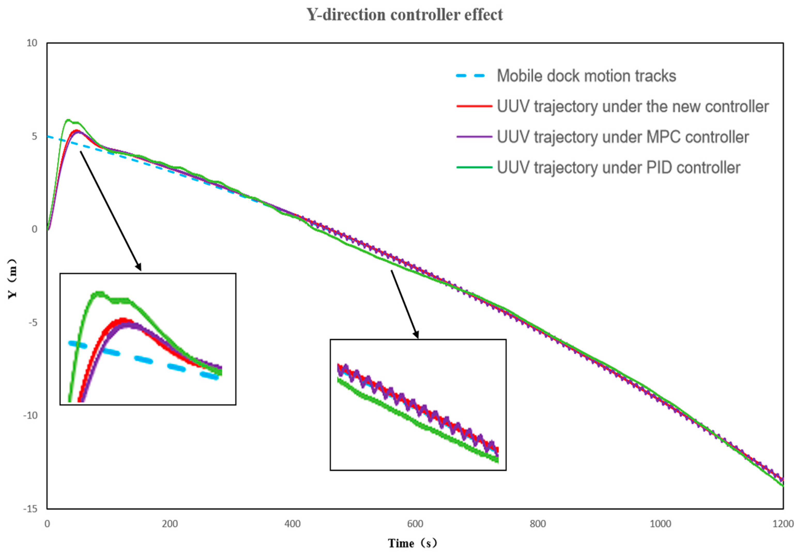
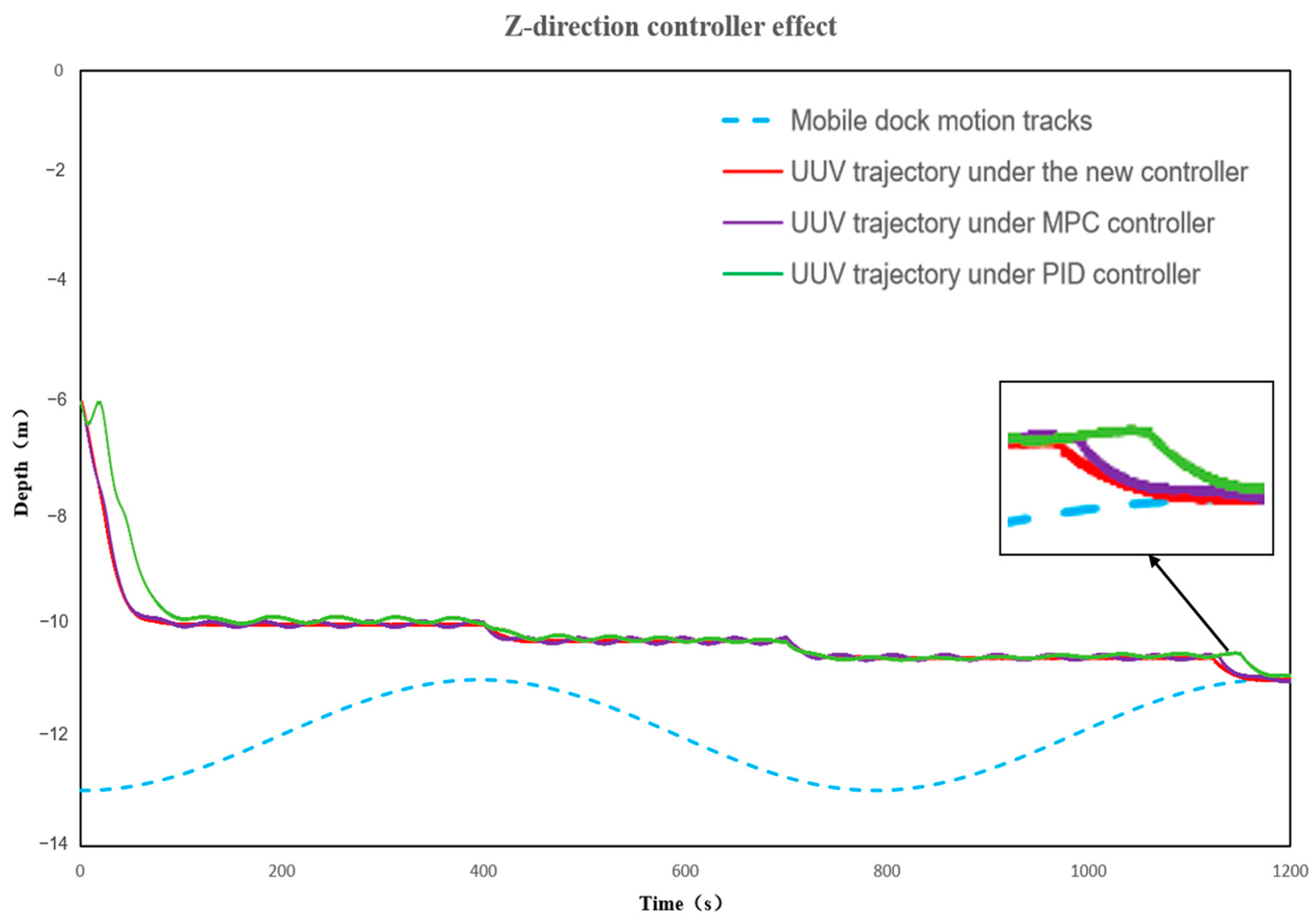
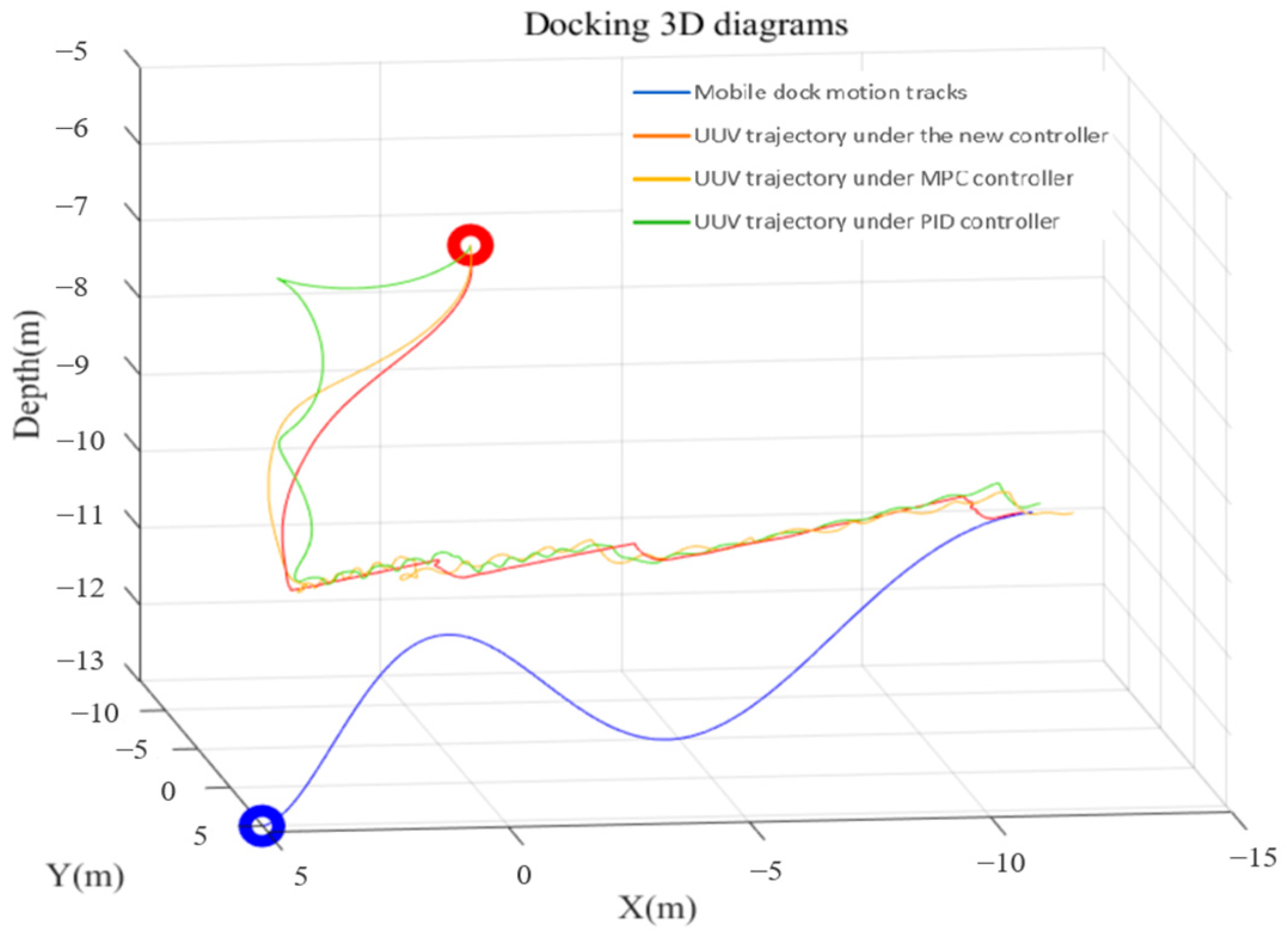
Figure 12, Figure 13, Figure 14, Figure 15 and Figure 16 present a comparative analysis of control performance during the complete sit-down docking process, encompassing both the long-range tracking phase and close-range descent docking phase. The results demonstrate that under multiple constraints and ocean current disturbances, both MPC controllers significantly outperform the PID controller, while the proposed controller exhibits superior performance compared to the conventional fixed-step MPC controller. These advantages are specifically reflected in: Convergence speed and overshoot during remote approach, and control precision during terminal tracking. (In Figure 16, the red and blue circles represent the initial positions of the UUV and the mobile docking station, respectively.)
The Table 2 below provides several sets of notable comparative data:
According to the comparative data, both the MPC and the new controller exhibit significantly smaller overshoots than the PID controller during remote approach, along with faster convergence speeds, which greatly enhances the UUV’s efficiency in locating the guidance light array and proceeding to the next phase.
The success criterion for docking is defined as end-point errors in both longitudinal and lateral directions being less than 0.5 m. Although the MPC controller largely meets this requirement, when the fixed-step MPC enters the close-range docking phase near the 400 s mark in the simulation, oscillations begin to occur. In contrast, the new controller effectively mitigates this issue. Furthermore, the data demonstrate that the new controller achieves higher end-point precision, enabling more reliable completion of the entire docking and recovery mission.
Furthermore, although discretization with a smaller step size yields a model that more closely approximates the original continuous system and offers higher accuracy—thereby potentially enhancing control performance—it may also increase the difficulty of iterative convergence for the optimization algorithm, consequently impacting computational time. To demonstrate real-time capability, extensive simulations indicate that the computation time per step ranges between 4 ms and 10 ms for a discretization step size of 0.25 s, and between 7 ms and 11 ms for a step size of 0.1 s. In both cases, the computation time is significantly shorter than the sampling period, confirming that the controller satisfies real-time requirements.

5.2. Experimental Validation

To validate the proposed control strategy, the accuracy of the simulation model, and the feasibility of partial algorithms, we conducted sea trials using the relevant UUV. The actuator configuration of this UUV is illustrated in Figure 5.
Figure 17 presents the overall procedure of the docking recovery test. The specific steps have been detailed in Section 2.2, with a corresponding flowchart provided in Figure 18.
As shown in Figure 17, the UUV is primarily equipped with the following key sensors:
(1)
Inertial Navigation System (INS): A self-developed device by the university, providing the UUV’s own position and attitude information.
(2)
Doppler Velocity Log (DVL): Measures the UUV’s velocity relative to water, thereby supplying speed data.
(3)
GPS: Provides the UUV’s latitude and longitude coordinates.
(4)
Depth Sensor: Measures and reports the UUV’s depth.
(5)
Ultra-Short Baseline (USBL)/Transducer: A self-developed system by the university, which acoustically measures the target’s distance and azimuth to determine its coordinates relative to the array.
(6)
Optical Camera: Identifies the guidance light array, enabling calculation of the relative position and attitude deviation between the UUV and the mobile docking station.
Additionally, the docking system includes the following components:
Surface Control System: Assigns mission modes, configures initial waypoints, sets depth/distance/time limits, and plans routes. When the UUV’s antenna surfaces, it also monitors the UUV’s position, attitude, and speed, allowing manual configuration of initial conditions (e.g., positive buoyancy).
Mission Control System: Allocates tasks, primarily executing commands from the surface system and ensuring the UUV responds accordingly.
Surface Monitoring System: Displays real-time footage from underwater and surface cameras on monitoring screens to observe the UUV’s status, enabling prompt responses to emergencies.
We conducted comprehensive sea trials for dynamic docking tests with this UUV. Acoustic guidance data were transmitted at 1 Hz, while optical guidance data were updated at 5 Hz. Both PID control and the proposed segmented controller were implemented, with the following comparative results:
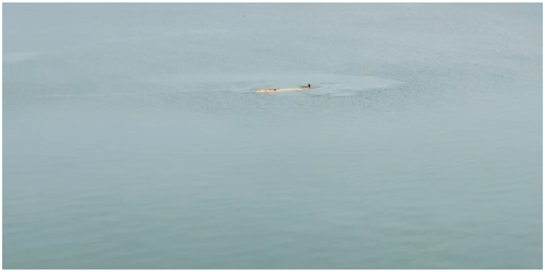
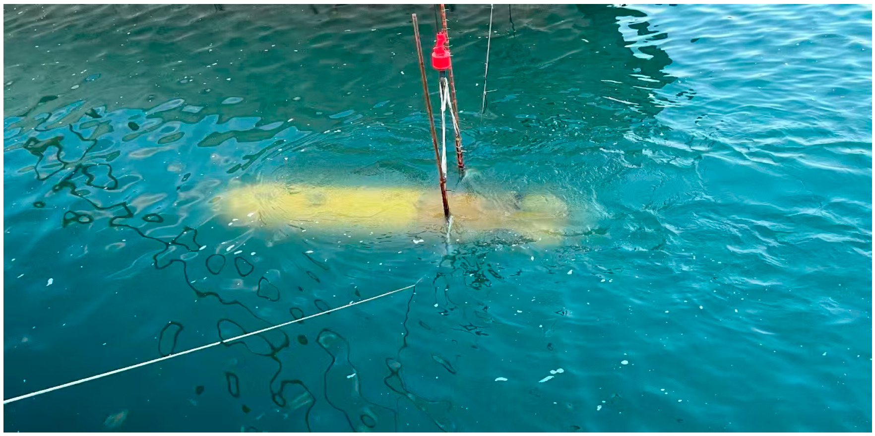
Figure 19 shows the lateral and longitudinal deviations of the UUV during the acoustic guidance approach phase under PID control, while Figure 20 presents the corresponding deviations under the improved MPC controller. Figure 21 illustrates the depth variation in the UUV under both controllers, and Figure 22 compares the heading angle tracking performance of the UUV following a mobile docking station under the two control schemes. The mobile docking station drifted randomly with ocean currents. The results demonstrate that after receiving the recovery command at 60 s, the UUV could effectively track the desired lateral/longitudinal positions and heading angle. However, during the close-range phase, the PID-controlled system failed to meet docking accuracy requirements for both positional and heading deviations due to current disturbances. As evidenced in Figure 21, the UUV could not transition to the gradual submersion phase under PID control. In contrast, the improved MPC controller satisfied all judgment criteria specified in Figure 18 throughout the docking process. Figure 23 depicts the long-range approach phase of the UUV during sea trials, while Figure 24 demonstrates its close-range control accuracy test.
The success/failure outcomes of 20 docking trials conducted by the UUV, along with the prevailing ocean current conditions (direction and velocity), are summarized in the Table 3 below.
The failure of the 10th trial was primarily attributed to misidentification by the optical guidance light array, which subsequently induced deviations in the terminal control phase. However, as evidenced by the outcomes of all 20 trials, the control strategy proposed in this study achieved a 95% success rate, demonstrating a significant enhancement in the reliability of docking operations.

6. Conclusions and Prospects

This paper proposes a seated recovery system, a UUV recovery strategy based on a mobile docking station, and an improved model predictive control (MPC) method. A fork-pillar recovery method is designed to address the dynamic characteristics of the mobile docking base, and a segmented recovery docking strategy is developed accordingly. To improve the accuracy of the UUV model, a quasi-LPV system is introduced, and thrust allocation and thrust delay are incorporated into the simulation system to enhance model fidelity. Based on the recovery strategy, a segmented variable-horizon MPC controller is proposed. Simulation results are compared with those of a PID controller, a traditional MPC controller, and the newly improved controller, demonstrating the effectiveness of the proposed method. Finally, field tests compare the PID controller with the new controller, and data from 20 docking trials show that the new method achieves a success rate of 95%, fully validating the feasibility of the proposed control strategy. Future research will primarily focus on thrust limitations and the optimization of guidance recognition algorithms with reference to studies such as [30,31]. Furthermore, comparative analyses with methods documented in other UUV control-related literature, such as references [32,33], should be incorporated to enhance the persuasiveness of the proposed methodology.

Author Contributions

P.H.: Investigation, Writing—Original Draft and Editing. W.Z.: Investigation, Funding acquisition. Q.W. and Y.S.: Figure Optimization and data Curation. All authors have read and agreed to the published version of the manuscript.

Funding

This research was supported by National Natural Science Foundation of China (Research No: E1102/52071108). Heilongjiang Province Natural Science Foundation (Research No: JJ2021JQ0075). National Natural Science Foundation of China (No: 52171297). Fundamental Research Funds for the Central Universities (No: 3072022FSC0401).

Data Availability Statement

Data is contained within the article.

Conflicts of Interest

The authors declare that they have no known competing financial interests or personal relationships that could have appeared to influence the work reported in this paper. All authors have read and agreed to the published version of the manuscript.

References

  1. Zhang, S. Determination of the legal status of maritime unmanned systems. Shanghai Leg. Stud. Collect. Anthol. Emerg. Rights Rule Law China 2021, 54, 47–56. [Google Scholar] [CrossRef]
  2. Miao, R.L. Research on Energy-Efficient Path Planning for Autonomous Underwater Vehicles. Master’s Thesis, Harbin Engineering University, Harbin, China, 2013. [Google Scholar]
  3. Xu, G. Development status and key technologies of UUV underwater docking technology. Acoust. Electron. Eng. 2019, 4, 1–5+9. [Google Scholar]
  4. Zhang, W.; Han, P.; Liu, Y.; Zhang, Y.; Wu, W.; Wang, Q. Design of an Improved Adaptive Slide Controller in UUV Dynamic Base Recovery. Ocean Eng. 2023, 285, 115266. [Google Scholar] [CrossRef]
  5. Bhat, S.; Panteli, C.; Stenius, I.; Dimarogonas, D.V. Nonlinear Model Predictive Control for Hydrobatics: Experiments with an Underactuated AUV. J. Field Robot. 2023, 40, 1840–1859. [Google Scholar] [CrossRef]
  6. Qi, B. Docking Control Algorithm for AUV Based on Model Predictive Control. Autom. Instrum. 2023, 38, 44–48+90. [Google Scholar] [CrossRef]
  7. Bian, Y.G.; Zhang, J.J.; Li, C.K.; Xu, B.; Qin, Z.; Hu, M. Distributed Model Predictive Depth and Longitudinal Velocity Control for Multiple AUVs. J. Hunan Univ. 2022, 49, 45–54. [Google Scholar]
  8. Yan, Z.P.; Yang, H.Y.; Zhang, W. Trajectory Tracking Control of Hexapod Robot Based on Model Prediction-Central Pattern Generator. Robot 2023, 45, 58–69. [Google Scholar]
  9. Zhang, Y.; Liu, X.; Luo, M.; Yang, C. MPC-Based 3-D Trajectory Tracking for an Autonomous Underwater Vehicle with Constraints in Complex Ocean Environments. Ocean Eng. 2019, 189, 106309. [Google Scholar] [CrossRef]
  10. Zhang, W.; Wu, W.H.; Teng, Y.B.; Gong, P.; Tang, Y.J. Docking Control of Dynamic Base Underwater Unmanned Vehicle Based on Satisfactory Model Predictive Control Under Constraints. J. Harbin Eng. Univ. 2022, 43, 108–118. [Google Scholar]
  11. Huang, Y.; Hu, F.; Yu, J.C.; Qiao, J.N.; Wang, Z.Y. Research on the Navigation Control System of Lightweight Long-Range AUV Based on Model Predictive Control Algorithm. J. Ocean Technol. 2020, 39, 32–38. [Google Scholar]
  12. Chen, Y.H.; Wu, H.Y.; Bian, Y.G. Trajectory Tracking Algorithm of Seabed Mining Vehicle Based on Sliding Mode Predictive Control. Inf. Control 2022, 51, 119–128. [Google Scholar]
  13. Wang, J.; Fader, M.T.H.; Marshall, J.A. Learning-Based Model Predictive Control for Improved Mobile Robot Path Following Using Gaussian Processes and Feedback Linearization. J. Field Robot. 2023, 40, 1014–1033. [Google Scholar] [CrossRef]
  14. Luo, Z.G.; Zhu, B.; Zheng, J.Y.; Zheng, Z.W. Robust Distributed Model Predictive Control for Formation Tracking of Nonholonomic Vehicles. IEEE/CAA J. Autom. Sin. 2024, 11, 560–562. [Google Scholar] [CrossRef]
  15. Tang, C.Y.; Zhang, M.L.; Fan, S.; Xia, J.F.; Wu, L.J. Research on Vehicle Path Tracking Control Technology Based on Model Predictive Control. Agric. Equip. Veh. Eng. 2024, 62, 71–75+104. [Google Scholar]
  16. Shao, P.Y.; Wu, J.; Ma, S. Model and Robust Gain-Scheduled PID Control of a Bio-Inspired Morphing UAV Based on LPV Method. Asian J. Control Affil. ACPA Asian Control Profr. Assoc. 2019, 21, 1681–1705. [Google Scholar] [CrossRef]
  17. Yan, Y.P.; Rao, B.; Liu, Y.J.; Feng, Y.B. Trajectory Tracking Control of Quadrotor UAV Based on Nonlinear Model Prediction. J. Shenyang Ligong Univ. 2024, 43, 36–43+49. [Google Scholar]
  18. Wu, C.F.; Feng, L.; Sui, D.; Wang, X.M. Application of Model Predictive Control Algorithm in Aircraft Automatic Landing Control System. J. Northwest. Polytech. Univ. 2004, 22, 140–144. [Google Scholar]
  19. Jiang, X.; Zeng, C.; Liu, J.; Gu, Q.; Wang, Z.; Pan, H. Dynamic Modeling and Analysis on the Cable Effect of USV/UUV System Under High-Speed Condition. J. Mar. Sci. Eng. 2025, 13, 125. [Google Scholar] [CrossRef]
  20. Menghini, M.; Mallipeddi, S.; Marchi, D.L.; Castaldi, P. Modelling and Parameter Identification of UUV Blucy for Control Design: A Benchmark Model. Ocean Eng. 2024, 313, 119617. [Google Scholar] [CrossRef]
  21. Zhang, W.; Wang, Q.; Wu, W.H.; Du, X.; Zhang, Y.; Han, P. Event-trigger NMPC for 3-D Trajectory Tracking of UUV with External Disturbances. Ocean Eng. 2023, 283, 115050. [Google Scholar] [CrossRef]
  22. Zhang, W.; Li, Z.X.; Zeng, J.; Wu, W. Distributed Event-Triggered Coordinated Control for Multi-UUV Recovery System with Time Delay. Ocean Eng. 2023, 283, 115138. [Google Scholar] [CrossRef]
  23. Zhang, W.; Wu, W.H.; Li, Z.X.; Du, X.; Yan, Z. Three-Dimensional Trajectory Tracking of AUV Based on Nonsingular Terminal Sliding Mode and Active Disturbance Rejection Decoupling Control. J. Mar. Sci. Eng. 2023, 11, 959. [Google Scholar] [CrossRef]
  24. Shao, P.Y.; Dong, Y.; Li, J.; Qu, G. Model Predictive Control for a Bio-Inspired Morphing UAV with Folding Wings Based on LPV System. J. Xi’an Aeronaut. Univ. 2020, 38, 3–10. [Google Scholar] [CrossRef]
  25. Yan, F.; Xiang, B.; Hu, J.; Chen, R.; Zhang, Z.; Liu, H.; Gao, C. Lateral Control of Autonomous Light Trucks Based on an Improved LPV Model. Automot. Eng. 2024, 46, 1403–1413. [Google Scholar] [CrossRef]
  26. Noor, H.N.; Visser, C.C.D.; Pavel, M.D.; Quaranta, G. Development of a Quasi-Linear Parameter Varying Model for a Tiltrotor Aircraft. CEAS Aeronaut. J. 2021, 12, 879–894. [Google Scholar] [CrossRef]
  27. Oliveira, A.L.; Guelton, K.; Motchon, M.K.; Leite, V.J. Refining Parameter Mismatch Handling in LPV Sampled—Data Controller Design. Automatica 2025, 180, 112470. [Google Scholar] [CrossRef]
  28. Qin, W.W.; Zheng, Z.Q.; Liu, G.; Ma, J.J.; Li, W.Q. LPV Robust Variable Gain Control for Hypersonic Vehicles. Syst. Eng. Electron. 2011, 33, 1327–1331. [Google Scholar]
  29. Wu, W.H. Research on Model Predictive Control Method for AUV Recovery and Docking Under Complex Constraints. Ph.D. Thesis, Harbin Engineering University, Harbin, China, 2024. [Google Scholar] [CrossRef]
  30. Ni, J.; Shi, J.; Zhan, Q.; Zhang, Z.; Gu, Y. An Improved U-Net Model with Multiscale Fusion for Retinal Vessel Segmentation. Mini-Invasive Surg. 2025, 5, 679–694. [Google Scholar] [CrossRef]
  31. Chen, X.; Ma, F.; Wu, Y.; Han, B.; Luo, L.; Biancardo, S.A. MFMDepth: MetaFormer-Based Monocular Metric Depth Estimation for Distance Measurement in Ports. Comput. Ind. Eng. 2025, 207, 111325. [Google Scholar] [CrossRef]
  32. Yan, Z.; Wang, M.; Xu, J. Robust Adaptive Sliding Mode Control of Underactuated Autonomous Underwater Vehicles with Uncertain Dynamics. Ocean Eng. 2019, 173, 802–809. [Google Scholar] [CrossRef]
  33. Gkesoulis, K.A.; Georgakis, P.; Karras, C.G.; Bechlioulis, C.P. Autonomous Sea Floor Coverage with Constrained Input Autonomous Underwater Vehicles: Integrated Path Planning and Control. Sensors 2025, 25, 1023. [Google Scholar] [CrossRef] [PubMed]
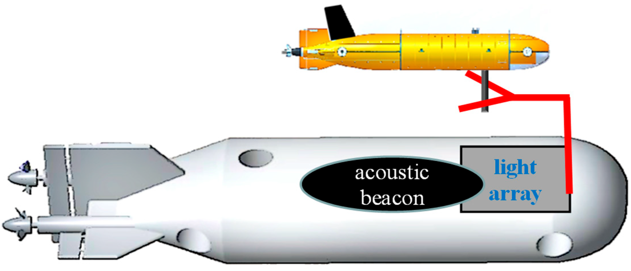
Figure 1. UUV and Mobile Docking Station.
Jmse 13 01861 g001
Figure 2. UUV coordinate system.
Jmse 13 01861 g002
Figure 3. Segmented docking.
Jmse 13 01861 g003
Figure 4. Block diagram of variable step-size LPV-MPC control based on UUV dynamic base docking.
Jmse 13 01861 g004
Figure 5. UUV vertical view.
Jmse 13 01861 g005
Figure 6. Actuator transmission system.
Jmse 13 01861 g006
Figure 7. Propeller speed response curve.
Jmse 13 01861 g007
Figure 8. Field of view of the optical guidance camera.
Jmse 13 01861 g008
Figure 9. Safe Navigation Range for Recovery and Docking.
Jmse 13 01861 g009
Figure 10. Step Control Tests for Four Degrees of Freedom (x, y, z, ψ) under Different UUV Models.
Jmse 13 01861 g010
Figure 11. Variation in Roll and Pitch Angles Under Different UUV Models.
Jmse 13 01861 g011
Figure 12. Comparative Analysis of Longitudinal Tracking Control for a Mobile Docking Station under Different Controllers.
Jmse 13 01861 g012
Figure 13. Comparative Analysis of Lateral Tracking Control for a Mobile Docking Station under Different Controllers.
Jmse 13 01861 g013
Figure 14. Depth Control Performance Comparison under Different Controllers.
Jmse 13 01861 g014
Figure 15. Heading Angle Tracking Control Comparison for Mobile Docking Station under Different Controllers.
Jmse 13 01861 g015
Figure 16. Three-dimensional Visualization Comparison of the Complete Docking Process.
Jmse 13 01861 g016
Figure 17. Overall Procedure of the Docking Recovery Test.
Jmse 13 01861 g017
Figure 18. Flowchart of the Docking Recovery Test.
Jmse 13 01861 g018
Figure 19. Position Deviations in Longitudinal and Lateral Directions under PID Control.
Jmse 13 01861 g019
Figure 20. Position Deviations in Longitudinal and Lateral Directions with the Novel Controller.
Jmse 13 01861 g020
Figure 21. Depth Variations in the UUV under PID Control versus the Novel Controller.
Jmse 13 01861 g021
Figure 22. Heading Tracking Performance under PID Control versus the Novel Controller.
Jmse 13 01861 g022
Figure 23. UUV Long-Range Approach Phase Maritime Testing.
Jmse 13 01861 g023
Figure 24. UUV Close-Range Control Accuracy Testing.
Jmse 13 01861 g024
Table 1. Coefficients of UUV.
CoefficientsUUV
m ( kg ) 1440
I x , I y , I z ( kg · m 2 ) 460, 1400, 1800
X u ˙ , Y v ˙ , Z w ˙ ( kg ) −217, 1, 700
X u , Y v , Z w ( kg / m ) −10, −80, −200
F B ( N ) 200
G M L ( m ) 0.03
Table 2. Comparison of Control Effects.
Control EffectsPIDMPCNew MPC
Overshoot (Y)1 m0.42 m0.41 m
Overshoot (Psi)19.7°7.4°7.3°
Convergence Time (X)90 s50 s40 s
Convergence Time (Y)110 s84 s83 s
Convergence Time (Z)100 s60 s60 s
Convergence Time (Psi)150 s80 s80 s
Terminal Error (X)0.47 m0.33 m0.30 m
Terminal Error (Y)0.39 m0.22 m0.12 m
Terminal Error (Psi)2.2°0.4°0.2°
Table 3. Docking Test Results.
Docking ExperimentOcean Current EnvironmentSuccess or FailureDocking ExperimentOcean Current EnvironmentSuccess or Failure
1st46°, 0.40 knSuccess 11th280°, 0.50 kn Success
2nd46°, 0.50 knSuccess 12th280°, 0.60 kn Success
3rd46°, 0.34 knSuccess 13th280°, 0.70 knSuccess
4th316°, 0.35 knSuccess 14th260°, 0.66 knSuccess
5th45°, 0.30 knSuccess 15th260°, 0.55 kn Success
6th45°, 0.10 knSuccess 16th180°, 0.13 knSuccess
7th60°, 0.15 knSuccess 17th180°, 0.20 knSuccess
8th100°, 0.20 knSuccess 18th78°, 0.10 knSuccess
9th100°, 0.10 knSuccess 19th85°, 0.10 kn Success
10th280°, 0.50 knFailure20th265°, 0.62 knSuccess
Disclaimer/Publisher’s Note: The statements, opinions and data contained in all publications are solely those of the individual author(s) and contributor(s) and not of MDPI and/or the editor(s). MDPI and/or the editor(s) disclaim responsibility for any injury to people or property resulting from any ideas, methods, instructions or products referred to in the content.