Article

Design and Experiment of Electric Control System for Self-Propelled Chinese Herbal Medicine Materials Transplanter

1
Nanjing Institute of Agricultural Mechanization, Ministry of Agriculture and Rural Affairs, Nanjing 210014, China
2
College of Modern Agricultural Engineering, Kunming University of Science and Technology, Kunming 650500, China
*
Author to whom correspondence should be addressed.
Agriculture 2025, 15(6), 621; https://doi.org/10.3390/agriculture15060621
Submission received: 1 February 2025 / Revised: 5 March 2025 / Accepted: 12 March 2025 / Published: 14 March 2025

Abstract

:
To address the challenges of low efficiency and poor quality in the transplantation of the roots and stems of Chinese medicinal herbs, an electromechanical control system for Chinese medicinal herb transplantation was studied. The electronic control system employs an STM32 single-chip microcomputer as the main controller, utilizes a Hall sensor to capture the movement speed of the transplanter, employs an encoder to monitor the working speed of the DC drum motor and provide feedback to the system, and drives a belt conveyor for transplanter movement using a DC drum motor. The fuzzy PID algorithm is used to adjust the speed of the DC drum in real time based on the difference between the captured speed and the actual monitored speed, ensuring precise matching between the transplanting operation speed and the transplanter movement speed. The control system was simulated using Matlab/Simulink 2022b software. Compared to the traditional PID control algorithm, the steady-state error was reduced by 36.41%, the steady-state time was shortened by 47.26%, the response time was shorter, there was no overshoot, and the robustness was good. Based on the simulation test, a real machine-verification experiment was conducted. The test results indicated that, when operated at the forward speeds corresponding to the low-speed first gear (Low 1) and low-speed second gear (Low 2), the Codonopsis pilosula seedlings exhibited the following characteristics: the exposed seedling rate was 1.1% and 1.5%, the injured seedling rate was 0.5% and 0.7%, the unplanted rate was 1.6% and 2.2%, and the transplant qualification rate was 96.8% and 95.6%, respectively. Similarly, for Astragalus membranaceus seedlings at these speeds, the corresponding rates were as follows: the exposed seedling rate was 1.3% and 1.9%, the injured seedling rate was 0.4% and 0.5%, the unplanted rate was 0.8% and 1.2%, and the transplant qualification rate was 97.5% and 96.4%, respectively. Both results met the design requirements. This study lays a theoretical and technical foundation for controlling the transplanting speed, improving the transplanting accuracy, and promoting the mechanized development of transplantation in traditional Chinese medicine.

Graphical Abstract

1. Introduction

The level of social and economic development in our country is constantly improving. The government attaches great importance to the people’s life safety and health needs, and there is an urgent need for the rapid and healthy development of traditional Chinese medicine (specifically, Chinese herbal medicines) to better serve the public [1,2]. The production scale of Chinese herbal medicines has been continuously expanded. By 2022, China had a production capacity of 5,185,200 tons of commonly used Chinese herbal medicines and a market size of more than 258.6 billion yuan, showing an accelerated growth trend [3,4]. Chinese herbal medicines can promote the development of characteristic agriculture, increase farmers’ income, and help implement the rural revitalization strategy. However, the mechanization level of Chinese herbal medicine production in China is still low, which seriously restricts the development of the Chinese herbal medicine industry, and the demand for the mechanization of the whole process of Chinese herbal medicine production is increasing [5]. The roots and stems of Chinese herbal medicines are an important part, and the level of mechanization directly impacts their quality and yield. The traditional transplanting operation for the roots and stems of Chinese herbal medicines mainly relies on manual labor. With the shortage of agricultural labor caused by urbanization, the requirements of modern agricultural industrialization, and the demand for smarter production, the development of electric control for transplanting machinery is becoming increasingly necessary [6,7,8]. Electronic transplantation has several obvious advantages over manual transplantation, including increased efficiency, greater consistency, reduced labor intensity, better adaptation to complex environments, improved plant survival, and environmental protection through energy saving. At the same time, with the development of science and technology and information transmission, electronic transplanters can also realize information and intelligence using navigation systems and remote sensing technology to monitor crop growth, further improving the intelligence of agricultural production. In general, electronic transplanters play an important role in improving agricultural production efficiency, lowering production costs, protecting farmers’ health, and promoting agricultural modernization. As technology advances and costs decrease, electronically controlled transplanters are expected to be applied in a wider range of agricultural production processes in the future [9,10,11].
At present, research on electronically controlled transplanting primarily focuses on pot-seedling transplantation and vegetable-substrate-seedling transplantation. Due to the difficulty of separating rhizome seedlings, artificially assisted transplantation is often employed in studies involving rhizome Chinese medicinal materials [12,13]. For research on electronic control systems, scholars both domestically and internationally have conducted extensive work on speed acquisition and anti-jamming measures. In field operations, given the noise interference in the working environment, various sensors are incorporated into the control system to detect operational parameters, enabling precise transplanting. These sensors are utilized in the system’s feedback loop to provide reliable representations of actual operational parameters. Subsequently, through the system’s main control algorithm, the precision of transplanting is achieved [14,15,16]. Developed countries such as the United States and Japan initiated earlier research on the control aspects of transplanters [17,18]. Xin Jin et al. designed a precision control system utilizing a GA–fuzzy PID controller, addressing issues of low precision and poor speed adaptability in the mechanized transplanting of rice potted seedlings. This system remains stable under external disturbances, exhibiting strong robustness and operational stability [19]. Wanzhi Zhang et al. designed a sweet potato seedling transplanting system using an Arduino control board to manage the coordinated movement of each component. The integrated positioning component ensures precise coordination between the transplanting device and the seedling conveying device, achieving rates of 4.13% for missed seedlings, 91.62% for qualified transplants, and 93.86% for qualified transplant depth, with a variation coefficient of transplant spacing of 1.90 and an average spacing between seedlings of 177.06 mm [20,21].
In the transplanting operation of the roots and stems of Chinese medicinal materials crops, artificial transplanting limits the development of the industry; with the continuous expansion of its demand, the advancement of mechanization urgently needs to be solved. This paper provides a solution for it. For this kind of crop, a working machine suitable for hilly and mountainous areas was designed and developed and equipped with an electronic control system, which can realize the semi-automatic operation of the roots and stems of Chinese medicinal materials through artificially assisted seeding, providing a new way of thinking for industrial development. By using the research on speed acquisition, the accuracy of mechanical transplanting was improved, and reasonable spacing between plants and rows and the number of unit-area plants were ensured.

2. Materials and Methods

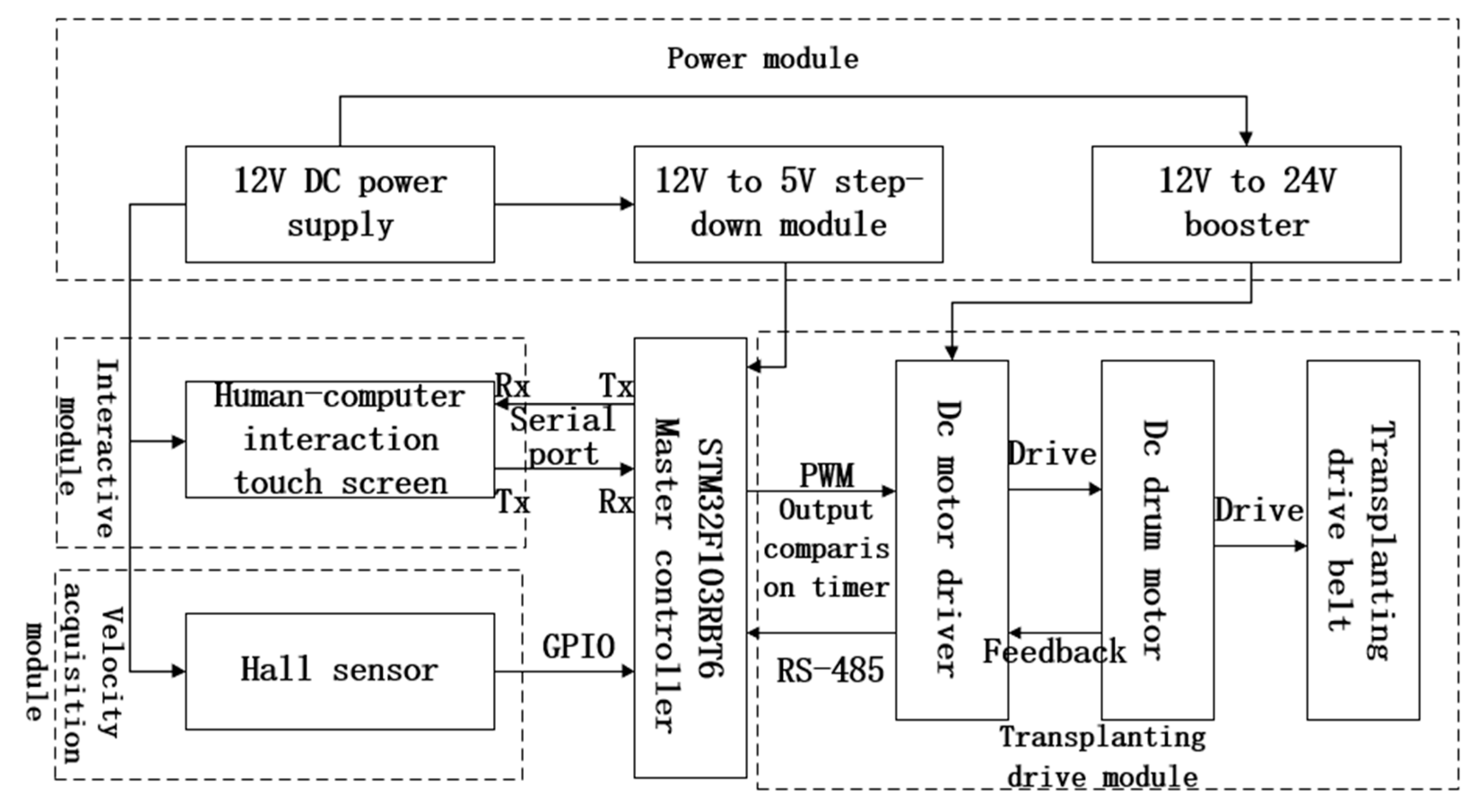
2.1. Overall System Design and Working Principle

The electromechanical control system for transplanting rhizome-type traditional Chinese medicinal herbs is primarily comprised of an STM32 main control chip (Geneva, Switzerland), a Hall sensor (Shenzhen, China), a human–machine interaction touchscreen (Shenzhen, China), a power converter (Guangzhou, China), an actuating motor (Ningbo, China), a motor driver (Ningbo, China), a 12 V power supply (Huzhou, China), and a voltage-reducer module (Shenzhen, China). The hardware structure block diagram of the control system is illustrated in Figure 1. The main controller and transformer modules are integrated onto a unified control board.
The schematic diagram of the entire machine structure is shown in Figure 2. Upon system power-up, the 12 V power supply provides electrical power to the human–machine interaction touchscreen and Hall sensor. This power is then boosted to 24 V by a power converter to serve as the energy source for the DC drum motor. Additionally, a 12 V to 5 V step-down module within the board supplies power to the main controller and connects to the system’s main control board’s step-down module, further reducing the voltage to 3.3 V/5 V for the microelectronic components. When the system power supply is activated, the operator engages the human–machine interaction touchscreen, inputs operational parameters on the parameter input interface, and confirms the settings for saving. The touchscreen then transmits operational parameters, such as planting distance or motor speed, to the system controller via serial communication. The system controller processes this information and sends a PWM signal with a corresponding duty cycle to the motor driver. Upon receiving this PWM signal, the driver initiates the rotation of the DC drum motor, while the operator simultaneously operates the transplanting equipment to commence movement. The Hall sensor speed-monitoring device, positioned on the chassis track, begins collecting speed signals. It calculates the real-time operational speed by leveraging the system’s counter and time frequency. This calculated speed is used to determine the theoretical desired operational speed of the motor. Meanwhile, the Hall sensor embedded within the DC drum motor provides the actual operational speed, serving as feedback for system control. Both speeds are input into the fuzzy PID controller module within the control system software, which outputs a corrected PWM signal to the driver. The driver controls the DC drum motor’s operation according to this algorithm. Additionally, the system communicates with the touchscreen via serial communication to provide real-time operational updates to the operator for their review. This process enables the precise transplanting and closed-loop control of root- and stem-based traditional Chinese medicinal herbs.

2.2. System Hardware Design

2.2.1. System Main Controller

Based on the functions required for control system design, such as memory size, operating frequency, etc., and considering the cost-effectiveness of current control chips, we selected the commonly used F4-series microcontroller STM32F405RGT6 (Geneva, Switzerland) and F1-series microcontroller STM32F103RBT6 (Geneva, Switzerland) for performance comparison. The processor parameters are listed in Table 1 below. The main system controller chip selected in this paper is the STM32F103RBT6 microcontroller, which is based on an ARM Cortex-M3 processor produced by STMicroelectronics (Geneva, Switzerland). This processor boasts excellent performance and a low cost, providing a solid platform for handling high-speed and complex peripheral communications. STM32F103RBT6 has excellent cost-effectiveness in non-industrial tracks and application environments, and the transplanter control system is only used for controlling multi-channel motors. Therefore, STM32F103RBT6 has significant advantages in this field.

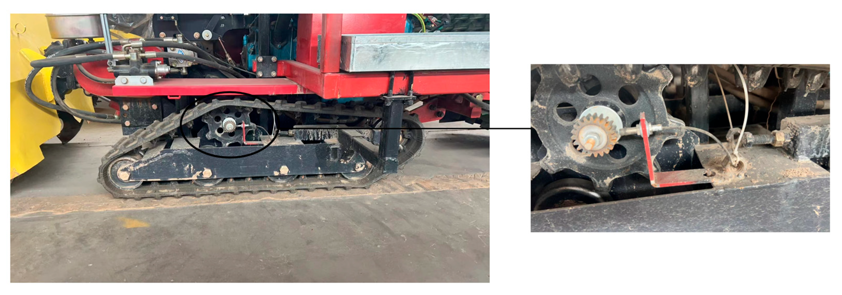
2.2.2. Speed Acquisition Module

In the control system, the acquisition of speed is of utmost importance. Common types of speed sensors include Hall effect sensors, photoelectric encoders, electromagnetic sensors, ultrasonic sensors, and inertial sensors, among others. These sensors can capture the corresponding signals under various conditions. Traditional Chinese medicinal herbs are predominantly cultivated in hilly and mountainous regions, where weak navigation signals can impair speed measurement, resulting in inaccurate navigation tests. During the transplanting operation of rhizome-type Chinese medicinal herbs, the operating speed of the transplanting machine is limited by the manual seedling-planting rate, leading to slow operations. Therefore, it is necessary to select sensor components suitable for low-speed acquisition. Hall effect sensors, being non-contact measurement devices, are characterized by their low cost and insensitivity to pollution. Consequently, the speed acquisition module of this system employs Hall sensors to measure the speed of the crawler drive wheel. The system’s main controller collects the voltage transition signals from the sensors, utilizing the counter and analog-to-digital conversion functions of the main controller to convert these signals into real-time data. Table 2 below presents the parameter specification table for the Hall effect sensor in the speed acquisition module.

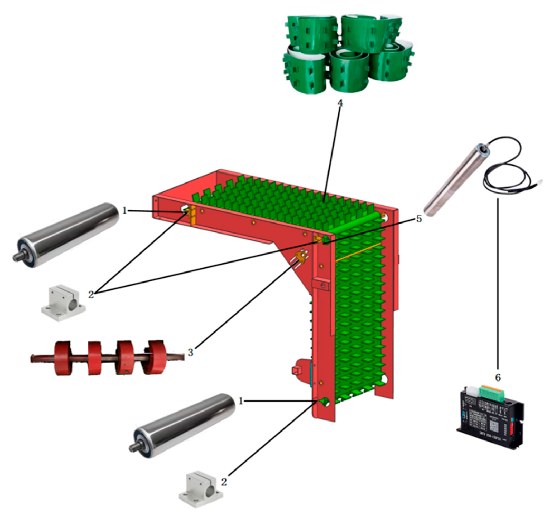
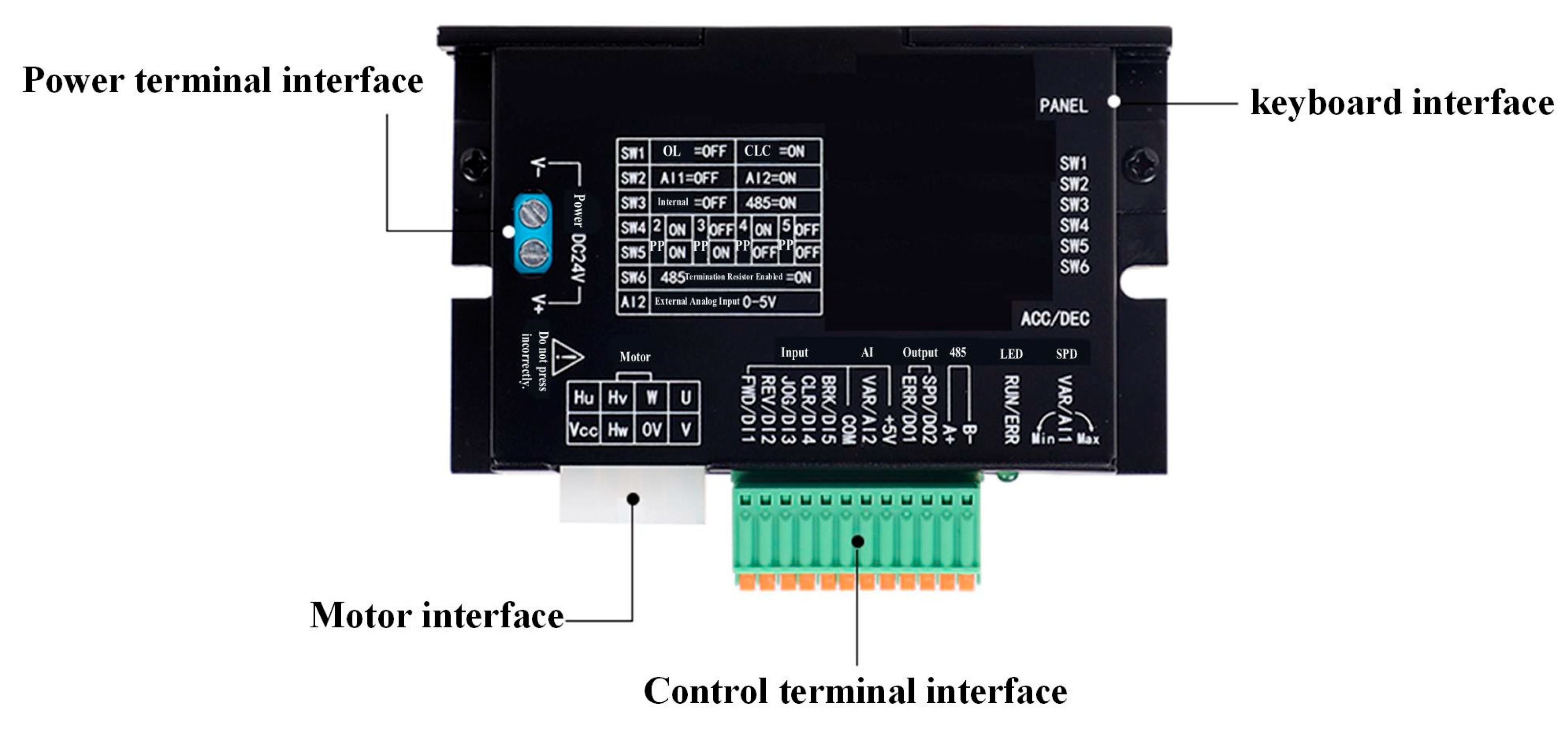
2.2.3. Transplanting Drive Module

The conveying transplanting components are primarily comprised of a DC drum motor, drive, separator conveyor belt, and tensioning device, among others. As illustrated in Figure 3, the separator conveyor belt functions as the actual transplanting actuator. The DC drum motor, acting as the driving shaft of the conveying device, provides the mechanical power source. The drive receives PWM signals transmitted by the main control system to accurately control the movement of the electric drum.

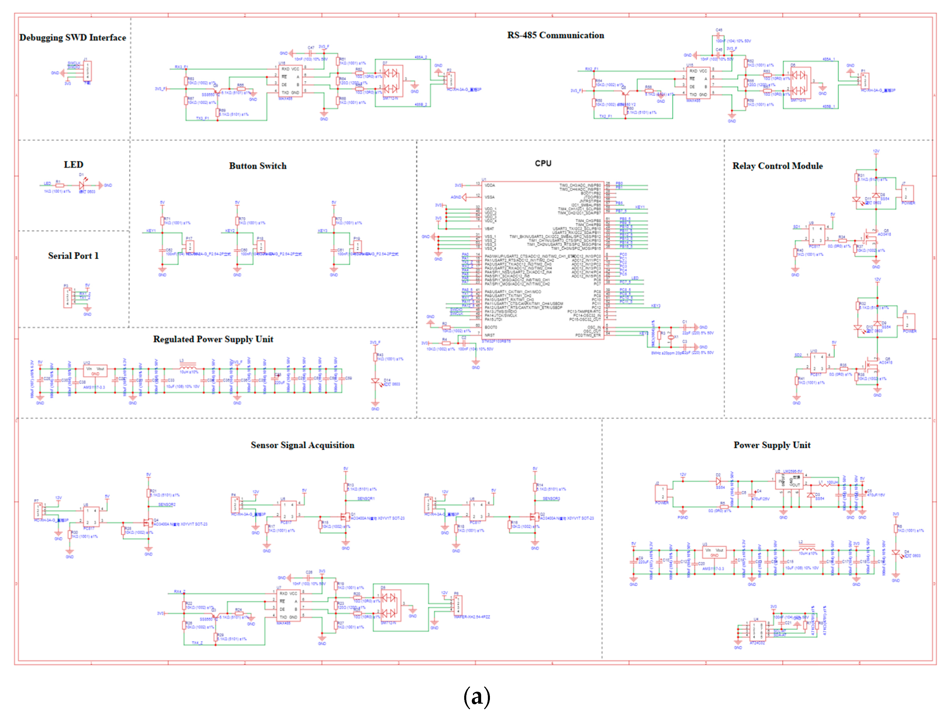
2.2.4. Hardware Circuit Design

As a device that converts electrical energy into mechanical energy, motors are widely used in various fields. Due to diverse working environments, the types of motors are also diverse. A drum motor, which integrates a motor and a drum, is widely applied in conveyor belt systems, industrial automation, and other areas. In transplanting operations, electric transplanting equipment is required to possess characteristics such as long life and high efficiency, while field operations necessitate good maintainability and low cost. Therefore, based on comprehensive consideration, this paper selects a 90 W brushless DC drum motor, whose parameters and specifications are shown in Table 3 below. The advantage of this drum motor lies in its internal integration of Hall sensors. Through RS-485 communication between the driver and the main controller, real-time rotational-speed information can be obtained, meeting the control system’s requirements for closed-loop control.
The 12 V power supply equipped on the walking chassis serves as the power module for the system. The input end of the power converter is connected to the 12 V power supply, while its output end supplies 24 V power to the driver and the main control board. The main control board contains a voltage converter chip that steps down the 24 V to 5 V/3.3 V. The main control board also features a touchscreen interface, which includes a 24 V power supply and a data interaction interface. The other end of the data interaction interface is connected to the PA5, PA6, and PA7 pins of the main control chip. The SPI interface of the microcontroller is utilized for data communication with the touchscreen. The photoelectric encoder and Hall sensor, serving as the speed measurement module, are connected to the PA0 and PA1 pins of the main control chip. The main control chip assigns the functions of TIM2 and AD to the PA0 and PA1 pins, respectively. The data from the photoelectric encoder and Hall sensor can be processed using TIM2’s counter and AD conversion to obtain real-time speed signals. The roller motor is connected to the driver, which receives input from the integrated motor terminal on the main control board. The other end of this terminal is linked to the PA3, PA4, PA8, and common ground terminals of the system’s master controller. The system’s master controller utilizes the TIM1 function to output controllable PWM signals. Figure 4 shows the schematic diagram of the overall control circuit, which is an important part of the electronic control system design, demonstrating the various modules and interfaces of the hardware design.

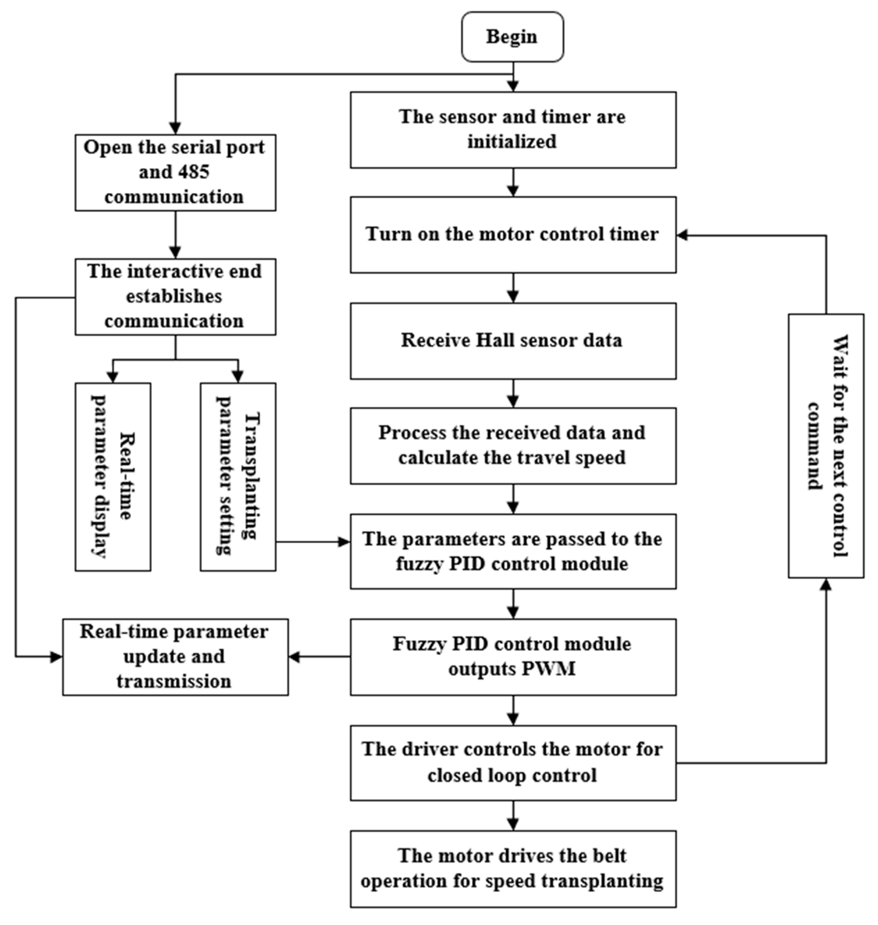
2.3. System Software Design

The software of the control system primarily consists of drivers for each module of the main control chip and communication and display software for the touch screen. The primary function of the hardware drivers of the main control chip is to activate each module to perform its respective tasks and execute them sequentially upon being called by the main program. The main purpose of the touchscreen communication and display software is to enable real-time interaction with the main control chip, thus ensuring that operators can monitor operational status in real time. The control flowchart for the entire main control chip is depicted in Figure 5. The main control chip and touchscreen communicate in real time via serial ports, detecting the operational parameters of the entire system. Based on sensor input, the operational status is updated in real time, and the required PWM signals are output through the control module’s algorithm to regulate the motor in real time, thereby ensuring uniformity and stability in the row spacing of the transplanted plants.

2.3.1. Serial Port Communication

The STM32 series of microcontrollers boasts extensive communication resources. The main controller selected in this paper is equipped with multiple types of communication protocols. Serial communication holds a particular advantage in short-distance data transmission. In this mode of communication, the transmitted information comprises low-capacity hex signals, and there are no stringent requirements for transmission speed. Therefore, this paper chooses to implement human–computer interaction through RS-485 communication, which can effectively increase transmission distance and enhance anti-interference capabilities. The accompanying hardware device is a Y-shaped 7-inch touchscreen, with its parameters listed in Table 4 below.
The touchscreen can effectively transmit string and hex data. By using the instruction library, which includes instructions like tx.txt=“0XFF0XFF0XFF”, text communication requests can be sent from the touchscreen to the main control chip. Upon receiving this information, the main control chip processes the statement and executes the corresponding command, then instructs the respective modules to perform the required operations. The USART HMI 1.67.2 software can be used for its development and design.

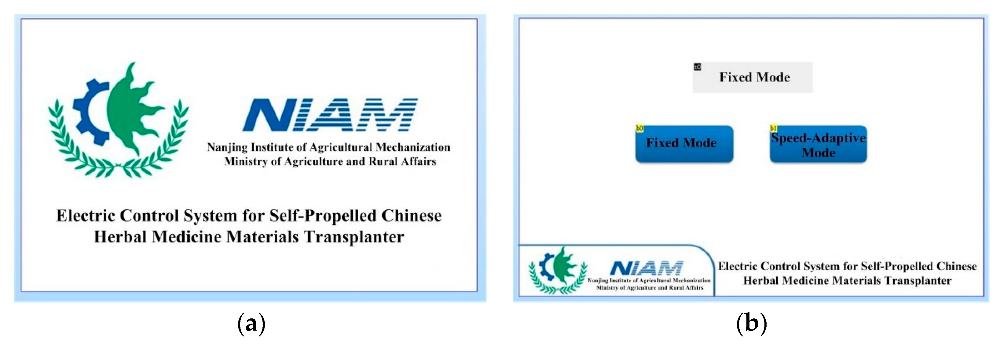
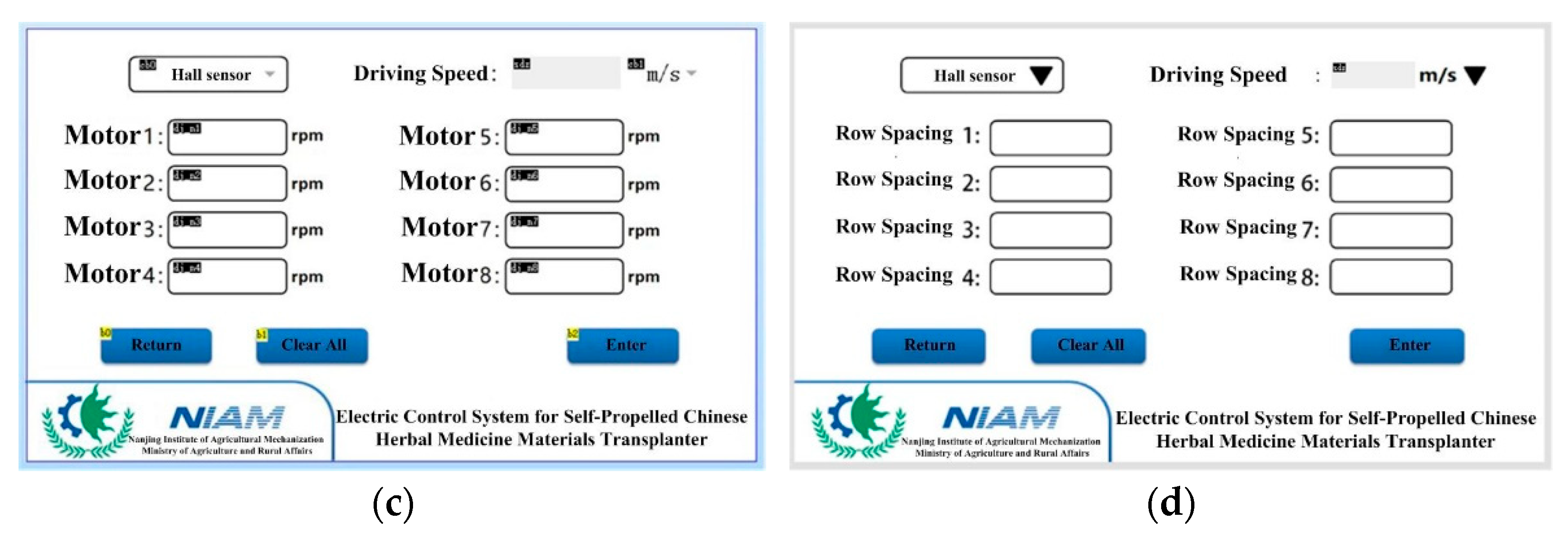
2.3.2. Design of Human–Machine Interaction (HMI) Unit

The HMI design diagram presented in this paper is depicted below. The design primarily comprises a boot-up background and three operational interfaces. As illustrated in Figure 6a, upon this background, the main control unit initiates the initialization of the timer and serial port. Simultaneously, during its initialization event, the touchscreen configures the baud rate to 115,200 (via the program parameter bauds = 115,200), aligning it with the MCU’s default baud rate, thereby establishing the initial conditions for communication. Figure 6b showcases the interface for selecting the transplanting mode. Within this interface, users can select the desired mode based on their requirements. Two modes are available: the Fixed Mode, wherein the transplanting control system operates according to the user-inputted operational speed, and the Speed-Adaptive Mode, which adjusts the transplanting speed in real time according to the driving speed, minimizing disturbances to the control system during the transplanting process. Additionally, users can input the coefficient for the transplanting motor on this interface to tailor the transplanting speed to different operational demands. Figure 6c,d depict the screens for the Fixed Mode and Speed-Adaptive Mode, which enable users to input operational parameters such as planting distance and motor speed.
When utilizing the touchscreen, the internally pre-installed software is automatically activated. This interface functions as the master of the entire system, with the circuit boards of various modules serving as slaves, facilitating real-time communication between them. At the boot-up interface, the touchscreen synchronizes with the main control unit, enabling users to input parameters and view data within the corresponding mode.

2.4. Development of a Velocity Measurement Model

2.4.1. Calculation of Overall Machine Moving Speed

In this paper, a combination of Hall sensors and gear-speed measurement is employed. The measuring gear is coaxially installed with the track’s driving wheel, while the Hall sensor is mounted radially to the gear, maintaining a consistent distance from the gear tip, as illustrated in Figure 7. The fundamental principle behind Hall sensor based speed measurement is that as the track’s driving wheel rotates the gear, its tooth tips periodically come into close proximity to and then move away from the Hall sensor, altering the magnetic field intensity surrounding the sensor. The Hall sensor detects these fluctuations in magnetic field strength and converts them into electrical signals. By analyzing the frequency or periodicity of these electrical signals, the rotational speed of the gear can be determined, which subsequently allows for the calculation of the track’s linear velocity.
The Hall sensor serves as the signal input module of the system, outputting raw data in the form of pulses. In the operation of the Hall sensor, speed measurement is conducted based on the statistical number of pulses, utilizing three primary methods: the M method (frequency measurement), the T method (period measurement), and the MPT method (combined frequency–period measurement). The system primarily employs the M measurement method for speed determination. Utilizing the system’s timer resources, TIM1 is configured to establish the speed measurement cycle t, while TIM2 is set in counting mode to record the number of pulses N generated within this cycle. During this period t, the number of pulses N outputted by the Hall sensor is measured to calculate the rotational speed of the gear, as illustrated in Formula (1):
t = ( P S C + 1 ) × ( A R R 1 + 1 ) H c l k
where t is period of track speed calculation (s); Hclk is the system clock frequency, 72 MHz; PSC is the value of the pre-divider; and ARR1 is the automatically overloaded value. Next,
n t e e t h = k 1 60 N Z 1 × t
where nteeth is speed measuring gear (r/min); k1 is speed measurement correction factor; N is the number of pulses outputted by the sensor in period t; and Z1 is the number of teeth on the speed measuring gear, which is also the number of pulses outputted by the sensor after one rotation.
The rotational speed of the track driving wheel and, subsequently, the travel speed of the transplanter can be calculated based on the number of pulses outputted by the Hall sensor within its time period t in the module. The calculation formula is provided below as Formula (3):
V 1 = k 2 × π × D 1 + 2 H 1 × n t e e t h × 1 60
where V1 is the traveling speed of the transplanter (m/s); k2 is track slip correction factor; D1 is the diameter of the root circle of the track driving wheel (m), 0.16 m; and H1 is track thickness dimension (m), 0.02 m.

2.4.2. Calculation of DC Drum Motor Speed

The schematic diagram of the conveying transplanting operation is shown in Figure 8. In practical applications, to ensure consistent transplanting speed and distance, the conveyor belt speed must be adjusted in real time as the forward speed changes. The conveyor belt speed, combined with the distance between partitions on the belt, determines the seedling transplanting frequency within a unit of time. Similarly, the forward speed of the transplanter and the transplanting distance between seedlings also ensure the seedling transplanting frequency. When these two frequencies are equal, the calculation of Formula (4) can be derived:
L p l a n t V 1 = L c l a p b o a r d V 2
where Lclapboard is partition distance (m), 0.05 m; Lplant is distance between transplanted plants (m); and V2 is conveyor belt linear speed (m/s).
Formula (5) can be obtained from Formulas (3) and (4).
V 2 = L c l a p b o a r d L p l a n t × k 2 × π × D 1 + 2 H 1 × n t e e t h × 1 60
The relationship between the speed of the drum motor and the speed of the conveyor belt is shown in Formula (6):
V 2 = k 3 × π × D 2 + 2 H 2 × n r o l l × 1 60
where k3 is correction coefficient of conveyor belt slip; H2 is conveyor belt thickness, 0.005 m; D2 is drum motor diameter, 0.060 m; and nroll is roller motor speed (r/min).
Formula (5) = Formula (6) derives the target rotational speed value for the drum motor. Based on the requirements for the overall machine speed and the spacing between transplanted plants, the calculation formula for the drum motor speed can be obtained by measuring the rotational speed of the speed-measuring gear (Formula (7)):
n r o l l = k 2 k 3 × D 1 + 2 H 1 D 2 + 2 H 2 × L c l a p b o a r d L p l a n t × n t e e t h

2.4.3. Roller Motor Speed Regulation Model

Figure 9 displays the drum motor driver, illustrating the physical-level interfaces as well as the modules connected to each interface. The motor is equipped with an integrated sensor to measure its actual speed, which is then inputted into the drum motor driver. Data transmission between the main controller and the drum motor driver is facilitated through the RS-485 communication protocol. The main controller calculates the theoretical speed (nroll) of the drum motor and determines the deviation between this theoretical value and the actual measured speed according to Formula (7). This deviation is inputted into the PID controller, which computes the control signal based on a fuzzy PID algorithm. Subsequently, the calculated control signal for the drum motor is used to adjust the duty cycle of the PWM (Pulse Width Modulation) signal. The adjusted PWM signal is then outputted to the motor’s drive circuit, enabling precise control of the drum motor’s speed.
PWM technology is an analog control method that modulates the bias of the transistor base or the gate of the MOS tube in response to changes in the corresponding load. This modulation alters the conduction time of the transistor or MOS tube, thereby enabling adjustments to the output of the switching-mode power supply. In DC drum motor control, PWM technology modifies the amplitude of the armature voltage by varying the width of the drive voltage pulse and coordinating with corresponding energy storage components in the circuit. This achieves the objective of altering the speed of the DC motor. A PWM signal is a continuous, variable pulse signal, with its duty cycle (i.e., the proportion of high-level time to the entire cycle) determining the motor’s average input voltage and, consequently, controlling the motor’s speed. An increase in duty cycle raises the motor’s average power-supply voltage, leading to an increase in speed. Conversely, a decrease in duty cycle lowers the motor’s average power-supply voltage, resulting in a decrease in speed. The representation of DC drum motor speed within the control system is as follows:
n r o l l = D × n m a x
where D is duty cycle (%) and nmax is the maximum speed of the motor in normal operation (r/min), 44.7 r/min.
The formula for calculating the duty cycle is (9):
D = C C R A R R 2 + 1 × 100 %
where CCR is pulse width and ARR2 is the automatically overloaded value.
Formulas (7)–(9) obtain the pulse width required by the target speed value of the drum motor:
C C R = k 2 k 3 × D 1 + 2 H 1 D 2 + 2 H 2 × L c l a p b o a r d L p l a n t ×   n t e e t h n m a x × ( A R R 2 + 1 )

2.5. Implementation and Simulation Verification of Control Algorithm

2.5.1. Design of Control Rules for a Fuzzy PID Controller

To ensure stable and reliable control of the speed of the DC drum motor, it is essential to design the fuzzy control rules appropriately. These rules can be tailored according to predefined fuzzy control principles. Based on the experience of adjusting conventional PID parameters, in the initial phase of the control system, the system deviation is significant. To expedite the system’s response, it is necessary to set a larger proportional coefficient, a smaller integral coefficient, and a smaller differential coefficient. As the control system brings the real-time speed closer to the desired speed, to avoid overshoot, a smaller proportional coefficient, a smaller integral coefficient, and a larger differential coefficient are required. In cases of overshoot, an appropriately sized proportional coefficient and a larger differential coefficient should be adopted. The rational design of fuzzy PID control rules is crucial, as it directly influences the actual performance of the controller. These fuzzy control rules are primarily summarized based on the operational experience accumulated by actual operators over time and are then formulated into fuzzy control statements through design and development.
In the design of fuzzy rules, the categorization of fuzzy subsets is divided into two categories: majority and minority subset designs. For instance, a design with three subsets may lead to excessive overshoot and prolonged adjustment times due to an overly simplistic rule base. Conversely, a design with multiple subsets can enhance the number of rules within the rule base, thereby improving system accuracy. However, excessively large subset designs may impose computational burdens on the system. In motor control schemes, a seven-subset design is predominantly adopted, which divides the error and error change rate into seven intervals: NB (negative large), NM (negative medium), NS (negative small), Z (zero), PS (positive small), PM (positive medium), PB (positive large), VS (very small), and VB (very large). The specific adjustment rules for the parameters of the fuzzy PID controller in this system are detailed in Table 5, Table 6 and Table 7. The system deviation e is defined as   { E i | i = 1 , 2 , , m } , the system deviation change rate e_c as { E c j | j = 1 , 2 , , n } , and the system’s output control quantity u as { U i j | i = 1 , 2 , , m ; j = 1 , 2 , , n } .
To investigate the sensitivity of system control to the number of fuzzy subsets, this paper conducted a comparative analysis using 3 × 3, 5 × 5, and 7 × 7 rule libraries. The findings revealed a delicate balance between rule complexity and system robustness, as detailed in Table 8. The data presented in the table underscore that the 7 × 7 fuzzy subset library exhibits superior sensitivity compared to the other two, albeit at the cost of some real-time performance. This aligns with the rationale behind employing the 7 × 7 fuzzy subset library in our control system, which prioritizes real-time performance. The ultimately chosen rule library, by ensuring precision while minimizing computational burden, underscores the soundness of our fuzzy logic design.

2.5.2. Fuzzy PID Controller Parameter Design

The fuzzy PID controller incorporates fuzzy control theory into the conventional PID controller, utilizing the system deviation (e) and the system deviation change rate e c as inputs. Instead of relying on the extensive experience of long-term operators, fuzzy control rules are employed to adjust the PID controller’s parameters ( K p ,   K i   a n d   K d ) in real time, catering to the varying requirements of the control system’s system deviation and deviation change rate at different moments. The input setting parameter values are as follows: maximum output speed of 25 r/min, minimum output speed of 23 r/min, and an input speed range of 0 to 10 r/min. Consequently, the fundamental discourse domain for system deviation (e) is set as [−25 r/min, 25 r/min], and the fundamental discourse domain for system deviation change rate ( e c ) is set as [−10 r/min, 10 r/min]. Based on these defined exact quantity domains, the respective quantized level domains are selected as E = {−25, −20, −15, −10, −5, −1, 0, 1, 5, 10, 15, 20, 25} for system deviation and E c = {−25, −20, −15, −10, −5, −1, 0, 1, 5, 10, 15, 20, 25} for system deviation change rate. To perform fuzzy reasoning, it is necessary to discretize the basic discourse domains into the fuzzy discourse domains of fuzzy subsets, which is achieved through quantization factors. Therefore, these quantization factors can be calculated using the formula derived from the quantized level domain. The calculation formula is provided below:
Q e = R e N e = 25 ( 25 ) 9 5.56   r / m i n
Q e c = R e c N e = 10 ( 10 ) 9 2.22   r / m i n
where Qe is quantization factor of system deviation; Re is range of system deviation theory domain; Ne is number of fuzzy sets; Qec is quantization factor of system deviation rate change; and Rec is system deviation rate of change scope.
In this article, the basic domains for K p , K i , and K d are selected as [−5, 5], [−1.25, 1.25], and [−2.5, 2.5], respectively. The formulas for the adjustment factors of the proportional coefficient change K K p , the integral coefficient change K K i , and the derivative coefficient change K K d are as follows:
K K p = 5 3 1.67
K K i = 1.25 3 0.42
K K d = 2.5 3 0.83
For the actual operation scenarios of motor speed control, the fuzzy control domain language expression variables for system deviation e, the rate of change of system deviation e c , and the tuning adjustment values K p (change in proportional coefficient), K i (change in integral coefficient), K d (change in differential coefficient) of fuzzy PID controller parameters are set as {NB (negative large), NM (negative medium), NS (negative small), Z (zero), PS (positive small), PM (positive medium), PB (positive large), VS (very small), VB (very large)}. NB indicates a significant negative deviation, necessitating substantial adjustments by the system to promptly reduce errors. NM signifies a moderate negative deviation, requiring moderate adjustments to decrease errors. NS represents a slight negative deviation, prompting minor tweaks to approach the target value. ZO denotes no deviation, with the system maintaining its current state or making minor adjustments for stability. PS indicates a slight positive deviation, necessitating minor adjustments to reduce errors and approach the target. PM signifies a moderate positive deviation, requiring moderate adjustments to decrease errors. PB represents a significant positive deviation, prompting substantial adjustments by the system to promptly eliminate errors. VS is utilized for fine-tuning extremely minor deviations to ensure system accuracy. VB is employed for emergency adjustments in cases of extreme deviations to maintain system stability.

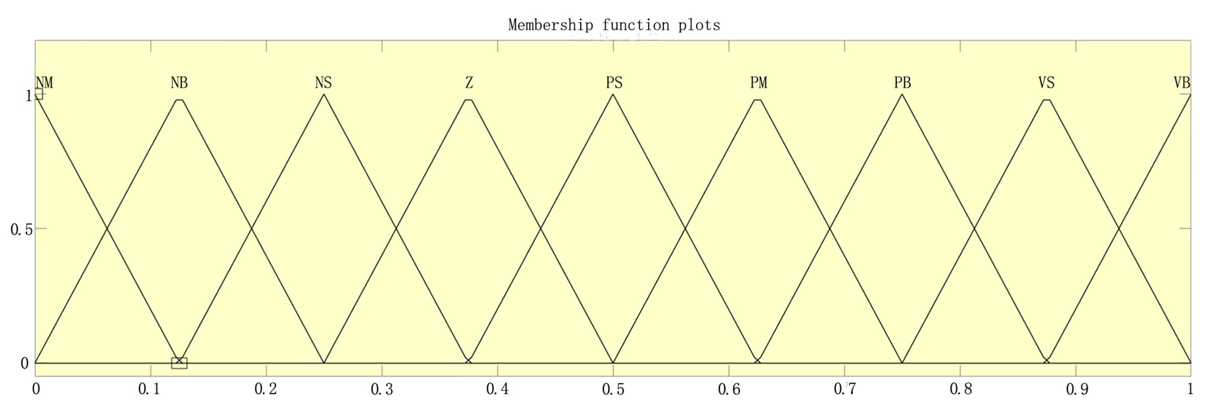
2.5.3. Membership Function Design of the Controller

The control of motor speed is marked by the complexity of practical environments. The membership functions for system deviation e, the rate of change of system deviation e c , and the increments of system control parameters K p , K i , and K d are chosen as triangular functions due to their low computational and memory requirements. The structure of the membership functions for system deviation e and the rate of change of system deviation e c is illustrated in Figure 10.

2.5.4. Fuzzy Reasoning and Defuzzification Process of Control Parameters

Taking the rotating speed of the drum motor as the controlled object within the control system, the fuzzy PID control system parameters’ adjustment values can be calculated using fuzzy control rules. In the actual system control procedure, it is imperative to convert the fuzzy control quantity obtained through fuzzy reasoning into a clear numerical value that can be utilized by the PID control module. In this paper, based on the requirements for control accuracy of the DC drum motor, the weighted average method, known for its higher precision, is selected for defuzzification, resulting in three adjustment values for the PID control parameters, namely:
K p = j = 1 9 ( μ   K p j K p j ) i = 1 9 μ   ( K p i )
K i = j = 1 9 ( μ K i j K i j ) i = 1 9 μ   ( K p i )
K d = j = 1 9 ( μ   K d j K d j ) i = 1 9 μ   ( K d i )
where μ ( K p j ) is membership of the fuzzy subset membership function of K p ;   μ ( K i j ) is membership of the fuzzy subset membership function of K i ; and μ ( K p j ) is membership of the fuzzy subset membership function of K p .
Based on the three adjustments to the PID control parameters, the three corresponding control parameter values are obtained, specifically:
K p = K p 0 + K p
K i = K i 0 + K i
K d = K d 0 + K d
where K p 0 is the initial value of K p ; K i 0 is the initial value of K i ; and K d 0 is the initial value of K d .
To assess the sensitivity of the control system to initial parameters, we utilized Matlab software within a simulation environment. By maintaining constant fuzzy inference rules, we examined the impact of individual variations in the proportional coefficient ( K p ), integral coefficient ( K i ), and differential coefficient ( K d ) on the system’s dynamic performance. We conducted this analysis for various initial parameter values, and the results are presented in Figure 11.
The results depicted in the figure reveal that Kp exhibits the highest sensitivity to the system’s response speed; however, an excessively high K p can lead to overshoot. K i primarily influences the adjustment of steady-state errors, albeit with the need to preclude integral saturation. Conversely, K d   demonstrates a notable capability in suppressing oscillations but is susceptible to noise.
Based on the operational characteristics of DC motors and the requirements of the control system under investigation in this paper, the system response must exhibit high-speed responsiveness and resistance to overshoot. Based on empirically observed operational patterns, the parameters are set as follows: K p 0 = 2, K i 0 = 0.1, and K d 0 = 0.05. These values serve as benchmarks for system control, enabling the control system to swiftly attain the target value while preventing overshoot. Subsequently, real-time adjustments to these parameters are made using fuzzy algorithms to achieve precise system control.

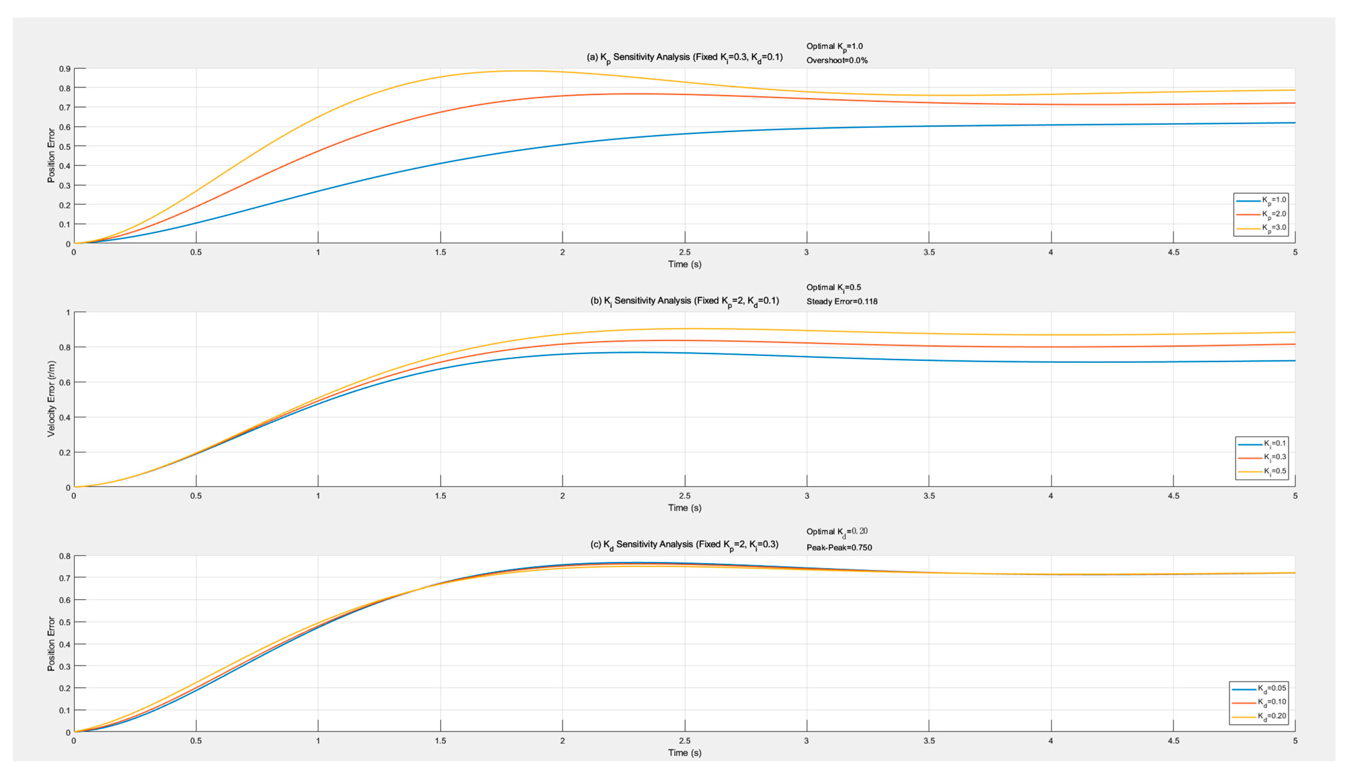
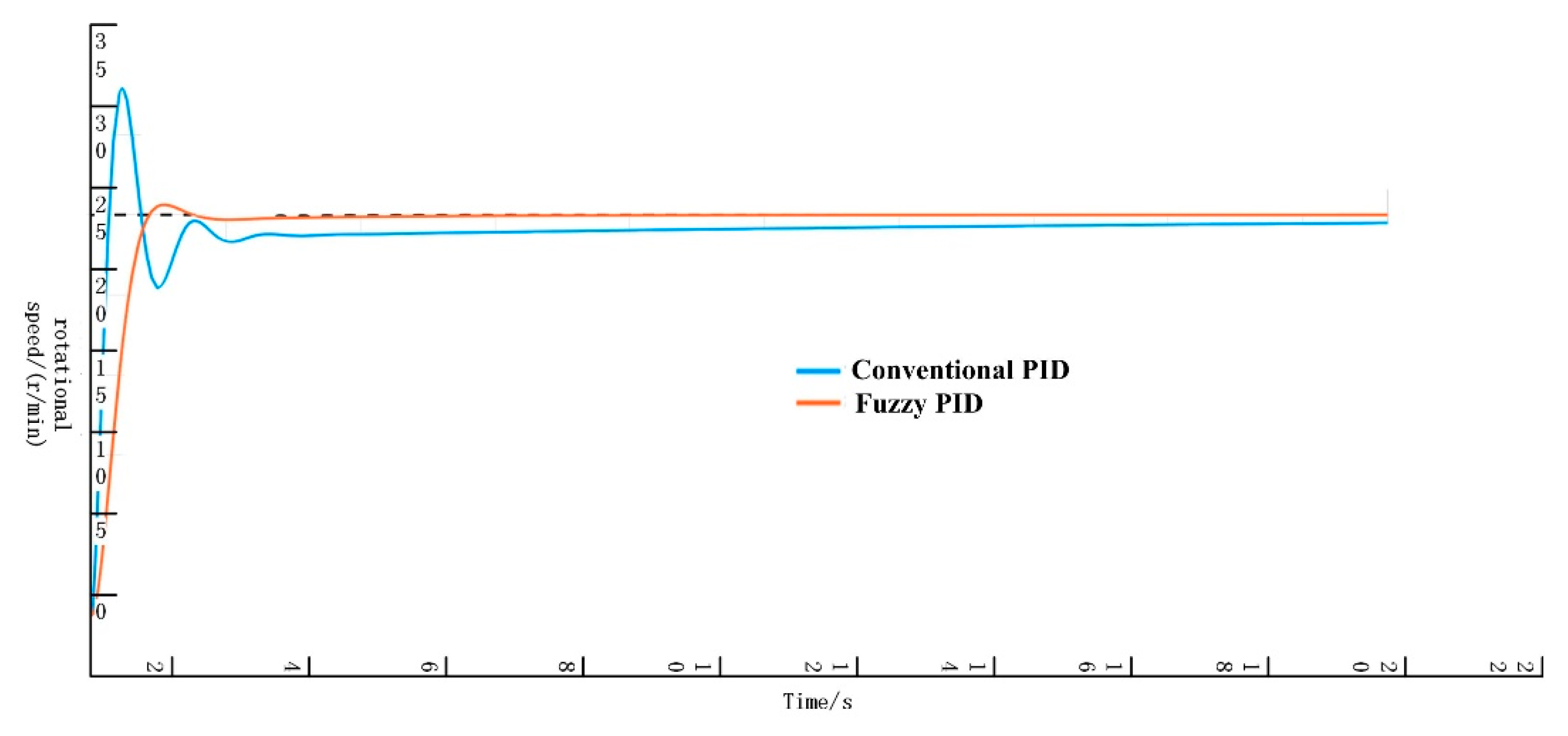
2.5.5. Result Analysis

The effectiveness of the fuzzy PID control algorithm in the overall design is verified using Matlab/Simulink. The program simulation model design is illustrated in Figure 12. In the program design, the Reference Input serves as the system input for the overall simulation model, simulating the expected value in practical applications. Both the conventional PID controller and the fuzzy PID controller are employed to process the data, with the output results displayed on the Response Scope. The simulation response curves for the fuzzy PID and conventional PID parameters of the control system are presented in Figure 13. When using fuzzy PID control, overshoot is avoided, and the dynamic response is rapid. By contrast, the conventional PID controller has been attempting to reach the target value but has not succeeded.
It can be seen from the calculations in Table 9 that, compared with conventional PID control, the system under fuzzy PID control exhibits a 36.41% reduction in steady-state error and a 47.26% reduction in steady-state time, with no overshoot. This demonstrates a certain superiority in control effect.

3. Results

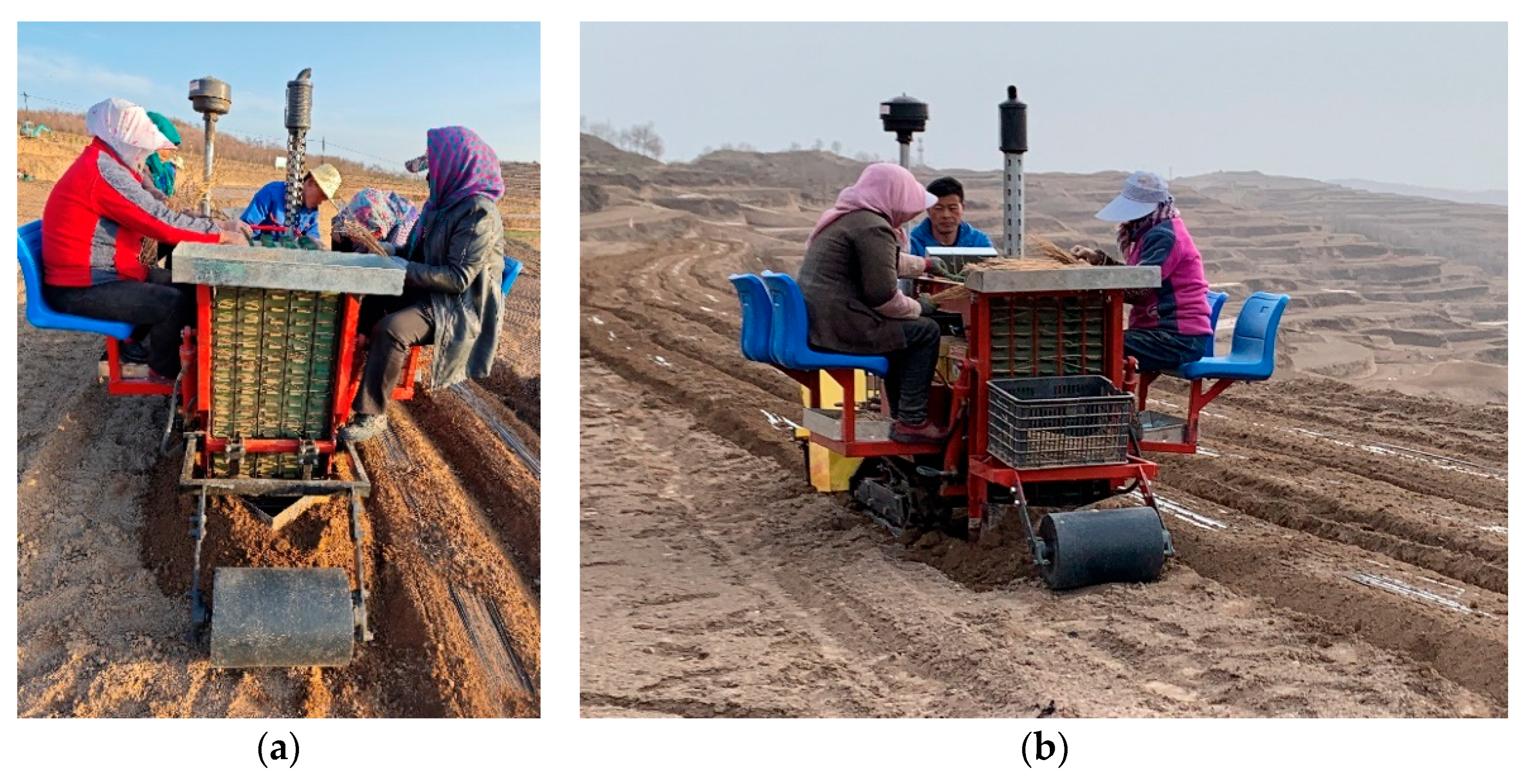
3.1. Key Parameter Calibration Test and Whole Machine Field Test

The performance measurement of the system relies on the transplanting-interval qualification index, which is directly influenced by two factors: the accuracy of acquiring the advancing speed of the transplanting equipment, and the motor control accuracy as well as the control response time. The transplanting machine employs a tracked chassis combined with an electronically controlled flexible belt transplanting mechanism specifically designed for Chinese medicinal herbs. The tracked chassis offers both high- and low-speed modes, each equipped with three gear shifts: low-speed first gear (Low 1), low-speed second gear (Low 2), low-speed third gear (Low 3), high-speed first gear (High 1), high-speed second gear (High 2), and high-speed third gear (High 3).

3.2. Calibration Test for Gear Tooth Number of Speed Measurement Gear

Because the accuracy of Hall sensors relies on the number of monitoring targets, it is imperative to ascertain the exact number of gear teeth in practical applications. An excessively low tooth count results in an insufficient sample size per unit time, thereby compromising the precision of speed monitoring. Conversely, an excessively high tooth count generates redundant samples, leading to data redundancy and increased processor load. The speed measurement gear was coaxially connected to the servo motor on the test bench, with the motor speed set to 363 r/min based on the equipment chassis’ maximum speed. Gears with varying tooth counts were utilized, and the lap speed monitored by the Hall sensor within 10 s was tested. This calibration test for gear tooth number was conducted, with sensor data retrieved by the upper computer, as presented in Table 10 below.
It can be observed that when the number of teeth is between 15 and 20, the insufficient number of teeth leads to a lack of data samples monitored per unit time, resulting in significant fluctuations in the monitored revolution count. However, after the number of teeth increases to 25, further increasing the tooth count does not enhance the uniformity of the monitored revolution count. Therefore, the optimal number of teeth for speed measurement is determined to be 25.

3.3. Calibration Test for Speed Measurement Correction Factor k1

In the mechanical transmission system of the equipment, the monitoring of travel speed is influenced by the transmission accuracy. To eliminate the impact of the track slip rate, the experiment is conducted on a horizontal hard surface. Using different gear speeds, the signals monitored by the Hall sensor of the tracked chassis are tested, and the monitored travel speeds are calculated. The average speed per unit distance traveled is taken as the actual experimental speed. The results are presented in Table 11.
The experimental results demonstrate that when the transplanting equipment maintains a constant speed within the range of 0.30 k m · h 1 ~4.00 k m · h 1 , the driving time taken to traverse a calibrated 200 m test section can be recorded. By using the experimental distance of 200 m and the recorded driving time to calculate the actual speed, the detection speed of the Hall sensor can be determined. The results indicate that the accuracy of the Hall sensor is above 96%. Within this speed range, the Hall sensor exhibits high monitoring accuracy and precision for this operational mode, fulfilling the working requirements of the transplanter. To further enhance the accuracy of speed acquisition, different speed measurement correction coefficients ( k 1 ) are designed for various gear positions based on experimental accuracy to eliminate speed errors resulting from power attenuation during mechanical transmission.

3.4. Track Slip Correction Coefficient k 2 Calibration Test

In actual operations, the ground is one of the primary factors influencing the accuracy of speed measurement, primarily due to the sliding effect between the ground and the track during motion contact. On hard surfaces, the slip rate of the track chassis is minimal, but in soil, it tends to increase with speed. Field tests were conducted in the Chinese Medicinal Herb Cultivation Base in Weiyuan County, Dingxi City, Gansu Province. Six different driving gears were used to obtain walking-speed data. The vehicle was operated by one driver and four seeders, with the rotating soil-covering device activated and the rear suspension lowered to simulate real field working conditions. The travel distance and time of the transplanting equipment were measured and recorded using a tape measure and stopwatch, respectively. This allowed for the calculation of the average forward speed of the transplanting equipment during the test period. Subsequently, the theoretical linear speed at a point on the chassis track was computed based on the number of revolutions of the track drive wheel obtained from the speed measurement module. The ratio of this theoretical linear speed to the actual forward speed of the transplanting equipment was used to calculate the track slip rate. The formula for calculating the track slip rate is as follows:
s = V 1 L T V 1 × 100 %
where s is the track slip rate (%); L is the total displacement of the transplanting equipment (m); and T is the record time (s).
According to the speed of different gears, the number of revolutions of the coaxial track driving wheel at 400 m driving distance was tested. Five tests were carried out at each gear, and the average value was taken. Due to the influence of the slip rate, the test result for the speed was slightly different from the real value. According to the meaning of slip rate, the track slip correction coefficient k 2 is introduced.
k 2 = 1 s
The experimental results are shown in Table 12. The test results indicate that the slip rate of this chassis ranges from 2.82% to 3.36% when operating in the slow first and second gears (0.31–0.51 km·h⁻1). As the speed increases, the growth rate of the slip rate remains relatively slow. In the range from the low-speed third gear to the high-speed third gear (0.83–3.58 km·h⁻1), the slip rate varies between 3.69% and 5.92%. As the speed further increases, the growth rate of the slip rate becomes more pronounced under these conditions. The disparity between these two scenarios is evident, with a notable increase in the slip rate. However, the impact of slip can be mitigated at the application level through the use of a modification coefficient.

3.5. Conveyor Belt Slip Correction Factor k3 Calibration Test

In practical applications, the belt conveyor relies on the frictional action of the DC drum motor to drive the belt. As the speed increases, the belt exhibits a tendency to slip. As the final execution unit of the transplanting component, any error between the belt and the motor (the power unit) can impact the transplanting operation. To investigate the speed relationship between the belt and the drum motor, experiments were conducted based on actual operating speeds, utilizing a speed measuring device to monitor the belt speed. Reflective plates were placed on the belt, and various motor speeds were set to conduct speed measurement experiments. The test results are presented in Table 13 below.

3.6. Drum Motor Control Precision Calibration Test

3.6.1. Drum Motor System Control Accuracy

In the entire system, the executive motor receives control signals from the driver to operate. However, during the transmission process of the entire mechanical system, various signals and noise interference can cause the output action to be less accurate than expected. This affects the accuracy of the entire transplanting operation, resulting in uneven transplanting spacing and hindering the effective growth of the plants. By calibrating the motor control precision and adding correction parameters, the error between the output speed and the expected speed can be improved. In the test, the control board is used as the lower-level controller to drive the motor. The motor is connected to a photoelectric encoder through coupling to detect the actual speed during operation. A laptop computer is connected to the control board and acts as the upper-level computer to monitor the actual speed fed back by the photoelectric encoder. Different control-speed programs are burned into the control board via the laptop, and the encoder’s feedback data are recorded and analyzed.
Table 14 presents the test results. It is evident from the table that, within the expected speed range of 5.21 r/min to 25.21 r/min, the absolute value of the control error for the system’s overall motor accuracy remains below 0.9%. This suggests that, under these operating conditions, the mechanical transmission of the transplanting equipment exerts minimal interference on the motor speed control and the motor control exhibits high precision, aligning with the operational requirements of the control system.

3.6.2. Motor Response Time

The system controls the motor’s operation based on the feedback of the traveling speed. The motor’s control response time to the system determines how quickly the motor reacts when the traveling speed changes, which, in turn, affects the transplanting accuracy. With the base traveling speed of the chassis of the transplanting equipment set at 0.30 km/h, the motor response time of the system was tested using speed increments of 0.5, 1.0, 1.5, 2.0, and 2.5 km/h. The test results, as shown in Table 15, indicate that the response time is not greater than 54 milliseconds.

3.7. Field Testing of Whole Machine Performance

To verify the effectiveness of the system in transplanting the roots and stems of Chinese herbal medicine crops, a precise transplanting field experiment was conducted on 15 April 2024, at the Demonstration Base for the Ripening Application of Mechanized Production Equipment for Codonopsis in Xinzhai Town, Weiyuan County, Dingxi City, Gansu Province. The experiment involved Astragalus membranaceus (Huangqi) and Codonopsis pilosula (Dangshen), which have different agronomic requirements for plant spacing: 5 cm to 8 cm for Codonopsis pilosula and 15 cm to 20 cm for Astragalus membranaceus. The transplanting speed of the entire equipment can be adjusted by altering the speed coefficient of the control system. The varieties used in the experiment were Weidang No. 1 (for Codonopsis pilosula) and Xiqi No. 1 (for Astragalus membranaceus). The target plant spacing for the experiment was set at 7 cm for Codonopsis pilosula and 18 cm for Astragalus membranaceus, according to their respective agronomic standards. The transplanting equipment was operated at the low-speed first gear and low-speed second gear. Each set of transplanting equipment was equipped with one operator and two or four seedling loaders, as shown in Figure 14. The efficiency of manual operation is relatively low, with approximately 10 workers required to transplant 1 mu (equivalent to 666.67 square meters) per day. The labor cost for each worker is 200 yuan per day, resulting in a total labor cost of about 2000 yuan per mu. By contrast, the transplanting machine featured in this article has an operating efficiency of 0.6 mu per hour and requires three to five auxiliary laborers. When calculated based on an 8 h workday, the labor cost per mu amounts to just 125 to 208 yuan, marking a significant reduction in labor expenses.
A statistical study was conducted on the transplanting volume using the low-speed first gear and low-speed second gear as the operating speeds of the transplanting equipment. According to the agronomic requirements of the transplanted crops, the target spacing between plants was set at 7 cm and 18 cm, respectively. Each ridge was 70 m long and 0.5 m wide. The transplanting numbers of Codonopsis pilosula (Dangshen) and Astragalus membranaceus (Huangqi) were counted over three ridges. The statistical results are presented in Table 16.
Theoretically, for rows with a length of 70 m, a width of 0.5 m, and row spacings of 7 cm and 18 cm, the theoretical transplanting numbers are 2000 and 778, respectively, with transplanting errors of −2.28% and −3.17% for the 7 cm spacing −0.64% and −1.20% for the 18 cm spacing.
According to the Gansu Province local standard DB62/T 4505-2022 [22], the performance indicators of this system include the exposed seedling rate, injured seedling rate, unplanted rate, and transplant qualification rate. The performance qualification indices are presented in Table 17. This experiment utilized the five-point method, and one set of experimental data collected 200 samples, with each set of data being randomly replicated five times to ensure an accurate average value.
Based on the data presented in Table 16 and in accordance with the inspection rules and judgment criteria outlined in the “Operation Quality of Root and Stem Chinese Herbal Medicine Transplanter” standard, the system determines that the operational quality is qualified. Seventy days after transplanting, the seedling emergence effect of Codonopsis pilosula and Astragalus membranaceus in the field is depicted in Figure 15, showcasing a satisfactory emergence effect that meets the design requirements.

4. Discussion

Lightweight Design and Enhanced Safety. Traditional transplanting machines often employ cumbersome transmission systems, such as gears and chains, which not only increase the overall weight of the equipment but also pose significant safety risks, including hand-clamping incidents. The adoption of electrically controlled conveyor belts effectively mitigates these issues. Streamlining the transmission structure drastically reduces the overall weight of the machine, making the transplanter more agile and user-friendly. Furthermore, the electronic control system’s precise regulation minimizes the likelihood of accidental contacts and injuries during operation, thereby enhancing operational safety.
Enhanced Intelligence and Precision in Transplanting. The electronic control system, governed by an STM32 microcontroller, possesses the capability to adjust plant spacing parameters in real time, catering to the diverse planting requirements of various Chinese medicinal herbs. By capturing the moving speed of the transplanting machine through Hall sensors and monitoring the operational speed of the DC drum motor, it employs a fuzzy PID algorithm for real-time adjustments. This ensures seamless synchronization between the transplanting speed and the machine’s moving speed. This intelligent control system not only bolsters transplanting accuracy but also provides adaptability for varying planting densities, fulfilling the diverse needs of traditional Chinese medicine cultivation.
Boosted Efficiency and Economic Benefits. The integration of an electronic control system has markedly accelerated the transplanting process and shortened the operational cycle. Additionally, precise transplantation guarantees the superior growth quality and yield of Chinese medicinal herbs, thereby yielding higher economic returns for growers. Moreover, the introduction of this electronic control system has alleviated the complexity of manual operations, reduced labor intensity, and significantly enhanced the comfort and convenience of the work process. In conclusion, it has significantly enhanced the efficiency, safety, and economic benefits of Chinese medicinal herb cultivation.

5. Conclusions

An electronic control system tailored for self-propelled outcrop film transplanters is introduced. The system employs Hall sensors and encoders for speed detection, leveraging an STM32 single-chip microcomputer to establish a robust platform for information processing and interaction. By precisely controlling the movement of transplanter components based on feedback from the DC drum motor speed and travel speed, the transplanting interval can be dynamically adjusted and updated in real time.
The difference between the monitored speed of the DC drum motor and the expected speed calculated from the walking speed serves as the feedback source. A fuzzy PID algorithm is utilized for closed-loop control, with each module programmed and configured using software. Simulations and analyses of the fuzzy PID algorithm were conducted using Matlab/Simulink software. The results demonstrate that the fuzzy PID control system reduces steady-state error by 36.41%, shortens steady-state time by 47.26%, and eliminates overshoot, indicating a superior control effect.
The accuracy of the control system was rigorously tested and analyzed. Compensation coefficients were introduced based on varying speeds, and comprehensive performance tests were conducted on the entire machine. The accuracy test results revealed that the primary source of error in the control system is the sliding action between the track and the ground during operation. At the sixth speed of the chassis, the slip rates were 2.82%, 3.36%, 3.69%, 4.45%, 4.80%, and 5.92%, with corresponding correction coefficients of 0.972, 0.966, 0.963, 0.956, 0.952, and 0.941, respectively.
The test results indicated that, when operated at the forward speeds corresponding to the low-speed first gear (Low 1) and low-speed second gear (Low 2), the Codonopsis pilosula seedlings exhibited the following characteristics: the exposed seedling rate was 1.1% and 1.5%, the injured seedling rate was 0.5% and 0.7%, the unplanted rate was 1.6% and 2.2%, and the transplant qualification rate was 96.8% and 95.6%, respectively. Similarly, for Astragalus membranaceus seedlings at these speeds, the corresponding rates were as follows: the exposed seedling rate was 1.3% and 1.9%, the injured seedling rate was 0.4% and 0.5%, the unplanted rate was 0.8% and 1.2%, and the transplant qualification rate was 97.5% and 96.4%, respectively. Both results meet the design requirements. This study establishes a theoretical and technical foundation for the real-time control of transplanting speed, enhancement of transplanting accuracy, and acceleration of the mechanized development of Chinese medicinal material transplanting.

Author Contributions

Conceptualization, Q.Y. and G.C.; methodology, X.Z., Q.Y. and Y.G.; software, X.Z. and Q.Y.; validation, X.C. and G.C.; formal analysis, Q.Y., X.Z., X.C., Y.G. and G.C.; investigation, Q.Y. and X.Z.; resources, Y.G. and Q.Y.; data curation, Q.Y. and X.Z.; writing—original draft preparation, Q.Y. and X.Z.; writing—review and editing, Q.Y., X.Z., and X.C.; visualization, Q.Y. and X.Z.; supervision, G.C. and Y.G.; project administration, Q.Y. and Y.G.; funding acquisition, Q.Y. and Y.G. All authors have read and agreed to the published version of the manuscript.

Funding

This research was supported by the Key Research and Development Program of the Xinjiang Uygur Autonomous Region, China (2023B02017), the China Agriculture Research System (CARS-25), and the Special Fund for Basic Scientific Research of the Chinese Academy of Agricultural Sciences (S202101-03).

Institutional Review Board Statement

Not applicable.

Data Availability Statement

The data presented in this study will be made available upon reasonable request.

Acknowledgments

We sincerely appreciate the careful and precise review by the anonymous reviewers and editors.

Conflicts of Interest

The authors declare that they have no competing interests.

References

  1. Xing, H.G. Exploring the Modern Value and Development Position of Chinese Medicine in the Perspective of Cultural Confidence. J. Nanjing Univ. Tcm (Soc. Sci.) 2022, 23, 11–16. [Google Scholar]
  2. Tan, Q.L.; Wu, Q.M. Current Situation and Optimization Strategies for the Development of Traditional Chinese Medicine Industry in China Based on SWOT Analysis. Health Econ. Res. 2023, 40, 18–21. [Google Scholar] [CrossRef]
  3. Liu, Y.F.; Xiang, W.; Yan, B.; Duan, Y.P.; Qu, Y.B.; Fang, Z.C. Present Situation and Countermeasures of Whole—Process Mechanization of Rhizome Chinese Herbal Medicines—Take the Bletilla Striata an Example. J. Agric. Mech. Res. 2024, 46, 1–7. [Google Scholar] [CrossRef]
  4. Bai, J.; Hao, F.; Cheng, G.; Li, C. Machine Vision-Based Supplemental Seeding Device for Plug Seedling of Sweet Corn. Comput. Electron. Agric. 2021, 188, 106345. [Google Scholar] [CrossRef]
  5. Yu, Q.X.; Zhang, L.H.; Cai, Z.P.; Liu, Y.; Gong, Y.; Cao, G.Q. Present status and prospect of mechanized production of Rhizome Chinese herbal medicine in Gansu Province. J. Chin. Agric. Mech. 2023, 44, 29–36. [Google Scholar] [CrossRef]
  6. Li, Y.X. Problems and Countermeasures of Chinese Medicinal Materials under Forests. Agric. Technol. Equip. 2020, 11, 175–176. [Google Scholar]
  7. Zhang, R.J.; Yu, Z.F.; Zuo, S.G.; Xing, X.L. Development of Traditional Chinese Medicine Industry under Forest in Yunnan Province. For. Inventory Plan. 2022, 47, 141–146. [Google Scholar]
  8. Bo, S.W.; Han, C.Z.; Li, Y. Present Situation and Future Prospect of Chinese Medicinal Materials Industry in Yunnan Province. North. Hortic. 2023, 13, 137–143. [Google Scholar]
  9. Ren, Z.Y.; Hu, M.J.; Yan, W.; Kun, L. Research status on seedling picking-up mechanism of dryland hole tray seedling transplanting machine. J. Chin. Agric. Mech. 2025, 46, 41–47. [Google Scholar]
  10. Hai, W.B.; Li, H.M.; Dong, A.H. Design and experiment of the picking component of eggplant bowl seedling transplanter. Journalof Chin. Agric. Mech. 2025, 46, 30–35. [Google Scholar]
  11. Xu, Q.M.; Li, H.W.; He, J.; Wang, Q.J.; Lu, C.Y.; Wang, C.L. Design and experiment of the self-propelled agricultural mobile platform for wheat seeding. Trans. Chin. Soc. Agric. Eng. 2021, 37, 1–11. [Google Scholar]
  12. Sharma, A.; Kumawat, L.; Singh, A. Development of Robotics in Vegetable Seedling Transplantation: A Future Research Direction. Int. J. Veg. Sci. 2023, 29, 577–591. [Google Scholar] [CrossRef]
  13. Zhang, B.; Wen, X.; Wen, Y.; Wang, X.; Zhu, H.; Pan, Z.; Yang, Z. Design and Testing of a Closed Multi-Channel Air-Blowing Seedling Pick-Up Device for an Automatic Vegetable Transplanter. Agriculture 2024, 14, 1688. [Google Scholar] [CrossRef]
  14. Jin, X.; Chen, Z.; Zhao, B.; Liu, M.; Li, M.; Li, Z.; Ji, J. Design and Experiment of High-Speed and Precise Positioning Seeding Control System for Rice Seedlings Based on Dual-Position Feedback Adjustment (DPFA). Comput. Electron. Agric. 2024, 217, 108548. [Google Scholar] [CrossRef]
  15. Zhai, C.; Lu, C.; Li, H.; He, J.; Wang, Q.; Chang, F.; Bi, J.; Wu, Z. A Precise Maize Seeding Parameter Monitoring System at the End of Seed Tube: Improving Monitoring Accuracy Using near-Infrared Diffusion Emission-Diffuse Reflectance (NIRDE-DR). Comput. Electron. Agric. 2024, 227, 109626. [Google Scholar] [CrossRef]
  16. Wang, S.; Yi, S.; Zhao, B.; Li, Y.; Wang, G.; Li, S.; Sun, W. Photoelectric Sensor-Based Belt-Type High-Speed Seed Guiding Device Performance Monitoring Method and System. Comput. Electron. Agric. 2024, 227, 109489. [Google Scholar] [CrossRef]
  17. Sun, X.W.; Xi, X.B.; Chen, M.; Huang, S.J.; Jin, Y.F.; Zhang, R.H. Design and experiment of control system of wheat mechanized uniform sowing. J. Chin. Agric. Mech. 2024, 45, 27–32. [Google Scholar] [CrossRef]
  18. Sharma, A.; Khar, S. Design and development of a vegetable plug seedling transplanting mechanism for a semi-automatic transplanter. Sci. Hortic. 2024, 326, 112773. [Google Scholar] [CrossRef]
  19. Jin, X.; Liu, J.; Chen, Z.; Liu, M.; Li, M.; Xu, Z.; Ji, J. Precision Control System of Rice Potting and Transplanting Machine Based on GA-Fuzzy PID Controller. Comput. Electron. Agric. 2024, 220, 108912. [Google Scholar] [CrossRef]
  20. Zhang, W.; Zhu, Q.; Zhang, T.; Liu, H.; Mu, G. Design and Control of a Side Dense Transplanting Machine for Sweet Potato Seedlings on Mulch Film. Comput. Electron. Agric. 2024, 224, 109193. [Google Scholar] [CrossRef]
  21. Ge, X.H. Design of Electrical Control System of Vegetable Transplanting Robot Conveying Device Based on PLC. J. Chin. Agric. Mech. 2024, 46, 122–126. [Google Scholar] [CrossRef]
  22. DB62/T 4505-2022; The Operating Quality of Rhizomatic Chinese Medicine Transplanter. Gansu Provincial Administration for Market Regulation: Lanzhou, China, 2022.
Figure 1. Control system hardware structure block diagram.
Agriculture 15 00621 g001
Figure 2. Schematic diagram of the whole machine structure. (1) Human–computer interaction touch screen; (2) Power converter; (3) DC drum motor; (4) The main controller; (5) Air switch; (6) Power supply; (7) Hall sensor; (8) Speed gear.
Agriculture 15 00621 g002
Figure 3. Schematic diagram of conveying transplanting parts. (1) Stainless steel roller; (2) Bearing support; (3) Tensioning wheel device; (4) Separator conveyor belt; (5) DC drum motor; (6) Drive.
Agriculture 15 00621 g003
Figure 4. System hardware circuit design diagram. (a) Schematic diagram of the circuit; (b) Circuit board design.
Agriculture 15 00621 g004aAgriculture 15 00621 g004b
Figure 5. Control flow chart.
Agriculture 15 00621 g005
Figure 6. HMI design drawing: (a) Description of what is contained in the first panel; (b) D Mode selection screen; (c) Fixed Mode page; (d) Speed with mode screen.
Agriculture 15 00621 g006aAgriculture 15 00621 g006b
Figure 7. Hall sensor assembly drawing.
Agriculture 15 00621 g007
Figure 8. Conveying transplanting operation diagram.
Agriculture 15 00621 g008
Figure 9. Drum motor driver.
Agriculture 15 00621 g009
Figure 10. Membership function of fuzzy PID controller.
Agriculture 15 00621 g010
Figure 11. PID parameter sensitivity analysis diagram.
Agriculture 15 00621 g011
Figure 12. Simulink model of control system.
Agriculture 15 00621 g012
Figure 13. Simulation response curves of fuzzy PID and conventional PID parameters.
Agriculture 15 00621 g013
Figure 14. Field experiment: (a) one operator and four seeding operators for Codonopsis pilosula; (b) one operator and two seeding operators for Astragalus membranaceus.
Agriculture 15 00621 g014
Figure 15. Effect of seedling emergence: (a) The seedling emergence effect of Codonopsis pilosula; (b) The seedling emergence effect of Astragalus membranaceus.
Agriculture 15 00621 g015
Table 1. Processor parameter table.
Characteristic ClassCharacterizationParameter Values
STM32F103RBT6STM32F405RGT6
MeromProcessor typeARMCortex-M3ARMCortex-M4
Floating-point unitSingle-precision FPUSingle-precision FPU
Clock and frequencyMaximum clock frequency72 MHz168 MHz
Flash memory64 KB1024 KB
SRAM20 KB192 KB
Peripherals and interfacesTimer countTwelveFourteen
DMA controllerSupportSupport
USB controllerUSB 2.0USB 2.0/USB OTG
CAN interfaceSupportSupport
Table 2. Hall sensor parameter table.
ProjectParameterProjectParameter
NameM3 inductive proximity switchOutput modeNPN is always on
MaterialMetalOperating voltage5~24 V
Product TypeA-M3Operating frequency1 KHz
Table 3. DC Roll Motor Specifications.
ProjectParameter
Rated power P (W)90
Gearbox seriesThree-level
Reduction ratio118
Maximum line speed V (m/min)4.80
Rated speed n (R/MIN)25.21
Rated torque T (Nm)16.59
Tractive force F (N)552.98
Length SL (mm)500
Radius R (mm)50
Voltage V (V)24
Table 4. Parameters of the Y-type touchscreen.
ProjectParameters
Dimension7.0 inches
Scale16:9
Touch typeR: resistive/C: capacitive
Resolution800 × 480
TFT typeTN
Brightness (nit)300
Effective display size (mm)154.08 (L) × 85.92 (W)
Operating voltage (V)4.65–6.5
Working current (mA)530
Rest current (mA)170
Operating temperature (°C)−20~+70
Flash capacity (Bytes)16 M
Power failure storage capacity (Bytes)1 K
Running memory (Bytes)512 K
Serial command cache (Bytes)4 K
RTC clockno
Expand I/Ono
Master frequency (Hz)200 M
Table 5. Fuzzy control rules for parameter K p .
e c e
NBNMNSZPSPMPBVSVB
NBPBPBPMPMZZNBPBPB
NMPBPBPMPSZZNBPBPM
NMPMPMPSPSZNSNBPMPM
ZPMPSPSNSNSNSNBNMNM
PSPSPSNSNSNSNSNBNSNS
PMNSNSNSNBNBNBNBNSNS
PBZNSNSNBNBNBNBNBNB
VSPBPBPMPMZZNBPBPB
VBPMPMPSPSZNSNBPMPM
Table 6. Fuzzy control rules for parameter K i .
e c e
NBNMNSZPSPMPBVSVB
NBPBPBPMPMZZNBPBPB
NMPBPBPMPSZZNBPBPM
NMPMPMPSPSZNSNBPMPM
ZPMPSPSNSNSNSNBNMNM
PSPSPSNSNSNSNSNBNSNS
PMNSNSNSNBNBNBNBNSNS
PBZNSNSNBNBNBNBNBNB
VSPBPBPMPMZZNBPBPB
VBPMPMPSPSZNSNBPMPM
Table 7. Fuzzy control rules for parameter K d .
e c e
NBNMNSZPSPMPBVSVB
NBPBPBPMPMZZNBPBPB
NMPBPBPMPSZZNBPBPM
NMPMPMPSPSZNSNBPMPM
ZPMPSPSNSNSNSNBNMNM
PSPSPSNSNSNSNSNBNSNS
PMNSNSNSNBNBNBNBNSNS
PBZNSNSNBNBNBNBNBNB
VSPBPBPMPMZZNBPBPB
VBPMPMPSPSZNSNBPMPM
Table 8. Control performance comparison table.
Fuzzy Rule Base ScaleOvershoot (%)Adjustment Time (s)Calculation Time (ms)
3 × 312.52.815
5 × 58.22.122
7 × 72.91.938
Table 9. Simulation results.
Control TypeSteady-State Error/(r/min)Adjust the Time/sMaximum Overshoot/(r/min)
Conventional PID1.843.4732.34
Fuzzy PID1.171.830
Table 10. Tooth number verification table.
Serial NumberThe Encoder Monitors the Number of Revolutions (r/10 s)
Tooth Number
1520253035
154.358.260.460.360.3
256.858.860.359.260.0
355.657.960.460.859.8
457.858.660.260.560.5
554.458.559.860.260.2
Mean value55.78 58.40 60.22 60.20 60.16
Table 11. Results of the k1 calibration test.
Actual Speed/ ( k m · h 1 ) Monitoring Speed/ ( k m · h 1 ) Accuracy Rate/%Error Compensation Coefficient k 1
0.330.3296.97%1.031
0.520.5198.08%1.020
0.850.8896.47%0.966
1.401.4298.57%0.986
2.202.2199.55%0.995
3.653.6699.73%0.997
Table 12. Results of the k2 calibration test.
Serial
Number
Gear
Position
Number of Turns of Track Driving Wheel/rTheoretical
Moving Distance/m
Record Time/sSlip
Rates/%
Correction
Factor k 2
12345Mean Value
1Low 1656.94654.55654.86655.67653.43655.09411.614645.162.82%0.972
2Low 2647.67659.89660.56660.21665.54658.77413.922823.533.36%0.966
3Low 3657.32662.47661.52662.33661.49661.03415.331734.943.69%0.963
4High 1670.54663.80665.42668.32663.21666.26418.621058.824.45%0.956
5High 2670.60660.87663.45669.32679.32668.71420.16663.594.80%0.952
6High 3679.90681.23678.87671.12672.21676.67425.16402.235.92%0.941
Table 13. Results of k3 calibration test.
Set the Roller
Motor Speed/(r/min)
Belt Theoretical
Linear Speed/(m/s)
The Tester Measured the Speed/(m/s)Relative Error/%Error Compensation Coefficient
12 k 3 45Mean Value
50.0183 0.01810.01830.01830.01810.01820.0182 0.69%0.993
100.0367 0.03620.03630.03610.03520.03610.0360 1.83%0.982
150.0550 0.05420.05460.05460.05340.05430.0542 1.38%0.986
200.0733 0.07280.07300.07310.07320.07220.0729 0.61%0.994
250.0916 0.09020.09060.08980.08950.08900.0898 1.98%0.980
Table 14. Motor accuracy table.
Desired Speed/(r/min)Actual Speed/(r/min)Relative Error/%
12345Mean Value
5.215.125.205.185.195.185.170.77%
10.2110.1110.0910.1410.1610.210.140.69%
15.2114.8915.0915.1815.1215.1815.090.79%
20.2120.1020.0920.0520.1420.1120.100.54%
25.2124.3825.1225.0825.1925.1624.990.87%
Table 15. Motor response time.
Speed Increment/ ( km · h 1 ) Response Time/(ms)Maximum Response Time/(ms)
12345
0.5485152505052
1.0475048494850
1.5535350525454
2.0485050484750
2.5525152535053
Table 16. Statistical table of transplanting numbers.
Gear PositionTransplanting Number
Codonopsis pilosulaAstragalus membranaceus
123Mean Value123Mean Value
Low 11944195619631954.33774776769773.00
Low 21940193419361936.67761770775768.67
Table 17. Table of eligible indicators.
CropGear PositionPerformance index
Number of SproutsPercentage of Crop Emergence/%Mean Value/%Number of Wounded SeedlingsSeedling Injury Rate/%Mean Value%OmissionsTransplanting Leakage Rate/%Mean Value/%Qualified Number of Plant SpacingPlant Spacing Pass Rate/%Mean Value/%
Codonopsis pilosulaLow 110.50%1.10%10.50%0.50%21.00%1.60%19698.00%96.80%
31.50%00.00%42.00%19396.50%
21.00%21.00%21.00%19497.00%
42.00%10.50%31.50%19296.00%
10.50%10.50%52.50%19396.50%
Low 221.00%1.50%10.50%0.70%42.00%2.20%19396.50%95.60%
31.50%10.50%42.00%19296.00%
31.50%21.00%63.00%18994.50%
42.00%21.00%31.50%19195.50%
31.50%10.50%52.50%19195.50%
Astragalus membranaceusLow 121.00%1.30%00.00%0.40%10.50%0.80%19798.50%97.50%
31.50%10.50%21.00%19497.00%
31.50%10.50%21.00%19497.00%
21.00%10.50%21.00%19597.50%
31.50%10.50%10.50%19597.50%
Low 221.00%1.90%10.50%0.50%31.50%1.20%19497.00%96.40%
42.00%10.50%21.00%19396.50%
52.50%10.50%42.00%19095.00%
52.50%10.50%21.00%19296.00%
31.50%10.50%10.50%19597.50%
Disclaimer/Publisher’s Note: The statements, opinions and data contained in all publications are solely those of the individual author(s) and contributor(s) and not of MDPI and/or the editor(s). MDPI and/or the editor(s) disclaim responsibility for any injury to people or property resulting from any ideas, methods, instructions or products referred to in the content.

