Abstract
Buckwheat is a highly nutritious coarse grain crop, yet its industrial processing has long faced two major challenges: the low whole-kernel rate of domestic dehullers and the poor local adaptability of imported equipment. To address these problems, a novel grinding disc-type dehulling machine was developed, featuring upper and lower discs with alternating deep–shallow composite textures to reduce kernel breakage and improve whole kernel rate. A 0–10 mm adjustable gap mechanism was incorporated to suit different buckwheat varieties and particle sizes, enhancing dehulling efficiency. Buckwheat grains were classified into four size ranges: 4.0–4.5 mm, 4.5–5.0 mm, 5.0–5.3 mm, and 5.3–5.7 mm. For all sizes, the optimal rotational speed was 12 r/min, with corresponding optimal gaps of 2.53 mm, 2.80 mm, 3.20 mm, and 3.40 mm, respectively. The whole-kernel rates under these conditions were 32.9%, 37.5%, 45.6%, and 55.1%, respectively, all above 30%, showing substantial improvement. For the 4.5–5.0 mm fraction, orthogonal tests revealed that a small gap (2.859 mm) achieved a dehulling rate of 89.9% and a whole-kernel rate of 38.03%, making it suitable for mass production. A larger gap (3.288 mm) combined with secondary dehulling increased the cumulative whole kernel rate to 50.26%, which is advantageous for producing high value-added products. The novel grinding disc structure balanced frictional and compressive forces on kernels, while the adjustable gap design improved adaptability. Combined with size classification and parameter optimization, this approach provides precise processing schemes for various buckwheat varieties and offers both theoretical and practical value for industrial application.
1. Introduction
Buckwheat, as an important cereal crop, has high nutritional, medicinal, and health value [,]. Buckwheat kernels are particularly favored by consumers for their ability to lower blood lipid levels, stabilize blood pressure, and promote metabolism []. In recent years, products primarily made from buckwheat kernels have increased rapidly, showing broad market prospects [,,]. The higher the kernel yield and quality, the greater the economic benefits. However, current post-harvest processing technology for buckwheat is still underdeveloped, and the dehulling technology has long been a bottleneck [,,]. The whole kernel rate from existing equipment is often too low to meet production needs []. In response, researchers have focused on improving equipment design, optimizing structural parameters, and refining the dehulling process of buckwheat to enhance dehulling efficiency and the whole-kernel rate while reducing the breakage rate. These efforts are essential for advancing the buckwheat processing industry [,,].
In the design and structural parameter optimization of buckwheat dehulling equipment, the most widely used buckwheat dehulling machines are primarily of two types: the double-disc type and the centrifugal impact type. The double-disc structure often employs sand discs, relying on the relative rotation between the sand discs to create a mutual grinding effect on the buckwheat, allowing for rapid separation of the buckwheat kernels from the hulls. A representative example is the 6QB-150 type sand disc buckwheat huller developed by the Inner Mongolia Agricultural University in China in the early 1990s []. Based on this machine, Chen et al. [], from the team led by Du Wenliang at Inner Mongolia Agricultural University, explored the effects of factors such as the rotation speed of the sand discs, the angle of inclination, the structural parameters, and the dehulling gap between the upper and lower sand discs on the milling rate and relative breakage rate during the buckwheat dehulling process, achieving optimal working parameters for the sand discs that resulted in a milling rate exceeding 30%. Fan et al. [] built upon this foundation by improving the material of the upper sand disc and modifying the surface texture, shape, and size of the working area, enabling the whole-kernel rate of the buckwheat in a single dehulling procedure to reach 44.03%. Some researchers have used the whole- and half-kernel rates of buckwheat after dehulling as indicators to optimize parameters such as the dehulling gap and dehulling speed of the sand disc buckwheat dehulling machine. After optimization, the whole- and half-kernel rates can reach about 50~60% [,]. The EBJ sand disc buckwheat dehulling equipment from the Swiss Brown company has high whole-grain and whole-hull rates, both approaching 60%. The centrifugal impact structure often uses a rotary disc or drum type, such as dual-roller, drum concave disc, roller plate, etc., relying on the centrifugal force generated by their high-speed rotation to fling the buckwheat toward the impact plate or dehulling machine shell, thereby achieving separation of hull and kernel. A representative example is the 6P-400 horizontal drum buckwheat dehulling machine developed by Zheng Decong’s team at Shanxi Agricultural University. Relying on this dehulling machine, Liang et al. [] explored the optimal working performance parameters of the buckwheat dehulling machine, achieving a dehulling rate of 82.5%, a half-kernel rate of 50.8%, and a whole-kernel rate of 16.3%. Zhu et al. [] designed a non-thermal tartary buckwheat dehulling machine, which dehulled buckwheat through two processes: “grinding” and “rubbing”. The dehulling rate reached 88.11%, and the whole-kernel rate reached 31.84%. The BASS model dehulling equipment from Swiss Brown company is a centrifugal dehulling device that mainly utilizes the impact of radial plates on a rotating disc to cause the buckwheat hull to rupture and then be flung onto a cylindrical impact plate, thereby separating the buckwheat kernel from the hull. Its whole-kernel rate and whole-hull rate both exceeded 90%.
In research on improving buckwheat dehulling processes, scholars generally focus on adjusting the physical and chemical properties of buckwheat hulls to simplify the shelling procedure and promote separation of the kernel from the hull. Studies have indicated that employing appropriate moistening treatment methods, in combination with flexible dehulling components, can significantly enhance dehulling efficiency and the rate of whole kernels. Moreover, pretreatment measures such as steam moistening and hot air conditioning have also been proven to improve dehulling outcomes, although specific process parameters and yields vary across different studies. Overall, physical and chemical pretreatments for buckwheat dehulling can further increase both the dehulling rate and the rate of whole kernels obtained [,].
In summary, although researchers have made significant efforts in the design and development of buckwheat dehulling equipment and in optimizing structural parameters, the whole-kernel rate of buckwheat dehulling machines in China remains at a relatively low level, typically only around 30%, and the actual production level may even be lower than this. Although the whole-kernel rate in developed countries can reach over 60–90%, upon introduction to the Chinese market, these devices often fail to achieve good results due to not meeting the requirements of different buckwheat varieties. After optimizing the buckwheat dehulling process, the whole-kernel rate of buckwheat has also significantly improved, but the inclusion of preprocessing techniques has made the dehulling process more complicated []. Currently, the most widely used buckwheat dehuller on the market is the sand disc type, but the material of the sand disc is usually silicon carbide, and its surface texture is difficult to change. As a result, the buckwheat often cannot achieve good dehulling results due to the limitations imposed by the surface texture of the sand disc []. Therefore, we designed a grinding disc buckwheat dehulling machine, which was validated through experiments to achieve a better dehulling effect. To increase the whole-kernel rate of buckwheat, improve dehulling efficiency, and reduce the breakage rate, we explored the relationship between the dehulling gap of the upper and lower grinding discs, the rotational speed of the grinding discs, and different buckwheat kernel sizes. Through single-factor experiments and response surface orthogonal tests, we conducted an in-depth exploration of the first whole-kernel rate and second cumulative whole-kernel rate of buckwheat dehulling. The research findings have theoretical significance and practical value for the development of buckwheat dehulling machinery, improving the whole-kernel rate and dehulling efficiency of buckwheat and reducing the breakage rate during buckwheat dehulling.
2. Materials and Methods
2.1. Design of a Grinding Disc Buckwheat Dehulling Machine
The structure of the grinding disc-type buckwheat dehulling machine is shown in Figure 1. It mainly consists of the frame 1, variable frequency speed control motor 2, transmission mechanism 3, gap adjustment mechanism 4, feeding hopper 5, upper grinding disc 6, lower grinding disc 7, receiving plate 8, scraping brush 9, and discharge port 10.
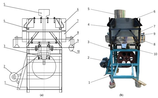
Figure 1.
Structural diagram of grinding disc buckwheat dehulling machine: (a) main view of the overall structure; (b) physical structure diagram of the overall structure.
The upper grinding disc 6 is fixed to the frame 1 by the screw-type gap adjustment mechanism 4, with the working grinding pattern facing down, while the feeding hopper 5 is located at the feed inlet at the top center of the upper grinding disc 6. The lower grinding disc 7 is connected to the drive shaft by a flange, and the drive shaft is supported by a tapered roller bearing on a bearing seat that is fixed to the frame 1. The lower end of the drive shaft is connected to the bevel gear reverser and the transmission mechanism 3 and variable frequency speed control motor 1, allowing for driving the lower grinding disc 7. The grinding pattern of the lower grinding disc 7 faces up, and its outer edge is connected to two fixed scraping brushes 9 evenly distributed by bolts. The receiving plate 8 is fixed to the frame 1 and is located below the lower grinding disc 7, with the discharge port 10 arranged below it. The gap range between the upper grinding disc 6 and the lower grinding disc 7 is 0–10 mm.
During operation, the lower grinding disc 7 rotates under the drive of the variable frequency speed motor 2 and the transmission mechanism 3. The buckwheat seeds enter the central area of the upper and lower grinding discs through the feeding hopper 5. Under the friction and squeezing action of the upper and lower grinding grooves, the seeds gradually move from the center of the milling discs towards the outer edge and are flung out from the outer edge of the discs, landing in the receiving plate 8. The material is then sent to the discharge port 10 by the scraping brush 9 that rotates together with the lower grinding disc 7, completing the dehulling process. The technical parameters of the grinding disc buckwheat dehulling machine are shown in Table 1 [].

Table 1.
Technical parameter table of the grinding disc buckwheat dehulling machine.
2.2. Key Component Design
2.2.1. Grinding Disc Structure Design
The grinding disc is a key component of the disc-type buckwheat dehulling machine. The texture on the working surface of the grinding disc has a crucial impact on buckwheat dehulling. The grinding disc for buckwheat dehulling was engineered by matching the kernel sliding angle to exceed the measured static friction angle, ensuring continuous flow and eliminating self-locking. An end-press tearing–rubbing mechanism was implemented via alternating deep and shallow surface textures: deep grooves concentrate compressive–tearing forces to initiate hull fracture, while shallow patterns remove residual hulls and guide kernels to discharge. Dual feeding ports with a spiral guide chamber, combined with a symmetrical disc layout, distribute loads evenly, optimize friction–compression balance, and maintain high dehulling efficiency with minimal kernel damage and reduced wear.
The texture of the lower grinding disc is shown in Figure 2a, and the physical diagram is shown in Figure 3a, showing with a diameter of 810 mm and a working surface width of 200 mm, featuring a mounting hole in the center. The working surface of the lower grinding disc contains ten sectors with 36° evenly divided grinding textures, with each sector configured with nine sets of alternating deep–shallow textures. The shallow textures (2 mm × 1.5 mm × 60 mm) form composite grooves with the deep textures at a spacing of 12 mm, with a cross-section shown in Figure 2b. The outer segment of the deep textures (60 mm) has a constant cross-section of 2 mm × 2.5 mm, while the inner segment of the texture features a triangular support structure, with the cross-sectional view and specific parameters shown in Figure 2c.
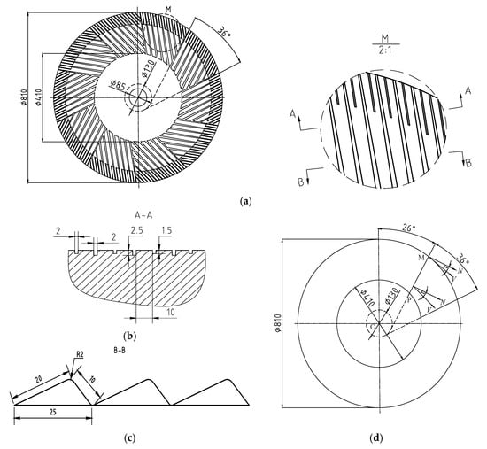
Figure 2.
Structural diagram of the grind pattern on the lower grinding disc: (a) texture diagram of lower grinding disc; (b) A-A cross-sectional view; (c) B-B cross-sectional view; (d) buckwheat grain motion analysis diagram: N—the normal at any point; V—the tangent at that point rotating with the grinding disc; Φ85–the diameter of the assembly hole is 85mm; Φ130–the diameter of the tangent circle to the two boundary lines of the 36° sector is 130 mm.
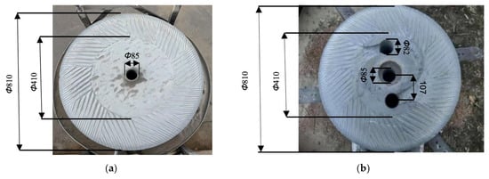
Figure 3.
Physical structure of the grinding discs: (a) physical structure diagram of the lower grinding disc; (b) physical structure diagram of the upper grinding disc.
According to the analytical method in reference [], the motion analysis during the dehulling of buckwheat grains is illustrated in Figure 2d. To enable the buckwheat to move outward along the grinding texture PM when the grinding disc rotates, without self-locking, the following conditions must be met:
τ > φ
In which PM is one of the boundary lines of the deep grinding groove.
τ is the sliding angle: the angle between the normal N of the grind pattern and the tangential speed V that rotates with the grinding disc.
φ is the friction angle between the buckwheat grains and the grinding disc. Its variation range is from 20 degrees to 30 degrees [].
Experiments show that the static friction angle between the buckwheat grains and the grinding disc is 25.17°; thus, the designed sliding angle of the grinding disc is 26°.
The structure of the grind pattern on the upper grinding disc is consistent with that of the lower grinding disc, and the combination of dual feeding ports and spiral guiding chambers achieves directional delivery of materials. A physical diagram is shown in Figure 3b. This alternating structure of deep and shallow patterns helps to improve the dehulling rate and whole-kernel rate, thereby enhancing the adaptability of the shelling machine.
Moreover, the upper and lower grinding discs are made of natural stone, the mechanical properties of which are highly consistent with the functional requirements of the milling design. The high hardness (Mohs hardness 6–7) ensures that the alternating deep–shallow groove patterns can maintain structural stability over prolonged operation, preventing deformation or wear caused by repeated friction []. In terms of chemical characteristics, the biostability and corrosion resistance of the stone material minimize potential interactions with proteins and flavonoid bioactives in buckwheat, while preventing the release of particulate matter that could contaminate the grains. These properties help preserve the nutritional integrity of the dehulled buckwheat kernels and ensure food safety, in full compliance with food-grade processing standards.
2.2.2. Gap Adjustment Mechanism
A structural diagram of the gap adjustment mechanism is shown in Figure 4. It mainly consists of connecting column 1, adjusting nut 2, adjusting screw 3, connecting frame 4, upper grinding disc 5, and lower grinding disc 6, among others. The lower grinding disc 6 is connected to the drive shaft via a flange, maintaining a fixed vertical position. The connecting column 1 and adjusting screw 3 are welded to the frame, while the connecting frame 4 is fixed to the upper grinding disc 5 with bolts. The upper grinding disc 5 is supported on four sets of columns by four uniformly distributed connecting frame 4 and adjusting nut 2. The gap between the upper and lower grinding discs is adjusted using adjusting nut 2, with an adjustment range of 0–10 mm.
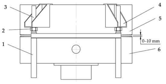
Figure 4.
Structural diagram of the gap adjustment mechanism.
2.2.3. Analysis of the Dehulling Mechanism of the Grinding Disc Buckwheat Dehulling Machine
The process of dehulling buckwheat with the upper and lower grinding discs mainly involves separation of the shell and the kernel through two methods: the rolling and rubbing method and the end-press tearing and rubbing method. Considering the texture of the upper and lower grinding discs in this design, the dehulling mechanism of buckwheat is primarily dominated by the end-press tearing and rubbing method when the gap is optimal []. Based on this, a force analysis of buckwheat grains during dehulling is shown in Figure 5.
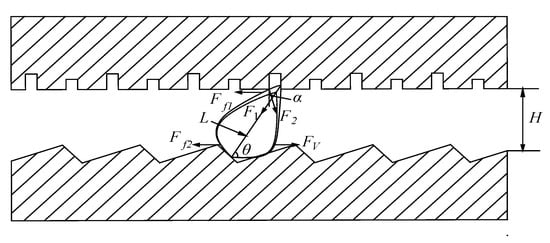
Figure 5.
Force analysis of buckwheat grains.
When the buckwheat seeds are subjected to end-press tearing and rubbing, they are positioned at an inclined posture between the working surfaces of the upper and lower grinding discs. From the geometric shape of the buckwheat and the texture of the lower grinding disc, it can be inferred that contact between the buckwheat seeds and the lower grinding discs occurs in a planar contact manner, if it forms angle θ. The force analysis is shown in Figure 5.
The compressive force exerted by the upper grinding disc on the buckwheat is as follows:
Fp = F1 sin θ + F2 cos α
Considering the buckwheat grain as an elastomer, the strain generated in the buckwheat grain due to compression mainly arises from force F1 acting along the length of the buckwheat grain at the front end of the grinding marks, while force F2 at the rear end of the grinding marks has a smaller effect on it. Therefore, the strain of the buckwheat is
S = L sin θ − H
According to Hooke’s law:
F1 = k S = k (L sin θ − H)
The friction force of the upper grinding disc on buckwheat is
Ff1 = μ Fp = μ (F1 sin θ + F2 cos α)
The friction force of the lower grinding disc on buckwheat is
Ff2 = μ (mg + Fp) = μ (mg + F1 sin θ + F2 cos α)
The centrifugal force exerted on buckwheat by the lower grinding disc is
FV = mωr2
By substituting Equation (4) into Equations (5) and (6), the final formulas for the two friction forces are obtained:
Ff1 = μ [k (L sin θ − H) sin θ + F2 cos α]
Ff2 = μ [mg + k (L sin θ − H) sin θ + F2 cos α]
In the equation:
F1—the pressing force exerted by the front structure of the grinding texture on the buckwheat;
F2—the pressing force exerted by the rear structure of the grinding texture on the buckwheat;
Ff1—the friction force of the upper grinding disc on the buckwheat;
Ff2—the friction force of the lower grinding disc on the buckwheat;
FV—the centrifugal force exerted on the buckwheat by the lower grinding disc;
k—the hardness of the buckwheat grains (N/mm);
L—the length of the buckwheat grains (mm);
H—the size of the dehulling gap (mm);
α—the angle between F2 and the vertical direction;
θ—the horizontal angle between the buckwheat grain and the lower grinding disc in the dehulling zone;
μ—the static friction coefficient when the buckwheat meets the upper and lower grinding discs;
m—the mass of the buckwheat grains (kg);
ω—the angular velocity vector of the lower grinding disc in the dehulling unit (rad/s);
r—the distance from the center of gravity of the buckwheat grain to the rotational center of the lower grinding disc (when the buckwheat moves to the edge of the lower grinding disc, it is equal to the radius of the lower grinding disc) (mm).
Based on the force analysis of buckwheat grains mentioned above, it can be seen that, under the combined action of the frictional force from the upper and lower grinding plates and the centrifugal force, a tearing effect occurs at both ends, causing the buckwheat shell to rupture. From Formulas (8) and (9), it can be observed that the dehulling gap H is a key parameter affecting the frictional force. The larger the gap, the smaller the frictional force, making dehulling difficult for the buckwheat. Therefore, when adjusting the gap in the end-compression tearing method, it should be slightly larger than the diameter of the buckwheat grains but smaller than their length. This force analysis provides a reference for the subsequent adjustment of the dehulling gap in experiments.
2.3. Experimental Materials and Methods
The experimental material chosen is the Shanxi geographical indication variety of red buckwheat. The samples were collected during the maturity period in 2024, ensuring that the grains were fully developed and free from mildew or insect damage. They were first cleaned using air separation or perforated sieves to remove stalks, dust, small stones, and other impurities, thereby ensuring the purity of the screened material. The moisture content was 11.04%.
Screening and grading of buckwheat grain size is completed using round-hole mesh sieves with hole diameters of 4.0 mm, 4.5 mm, 5.0 mm, 5.3 mm, and 5.7 mm []. Additional experimental equipment includes a caliper, a gauge, an SF-400C model precision balance (capacity 500 g, accuracy 0.01 g) (Yiwu Diheng Weighing Apparatus Co., Ltd., Jinhua, China), an electronic scale (capacity 30 kg, graduation value 10 g), a disc-type buckwheat dehuller, and so on.
The buckwheat dehulling experiment is designed with the goals of increasing the whole-kernel rate, improving the dehulling efficiency, and reducing the breakage rate, following an approach of variable control, single-factor investigation, and multi-parameter optimization. First, seed grading is employed to ensure uniform particle size in the test materials, thereby eliminating the influence of size variation on the dehulling outcome. Next, single-factor experiments are conducted to examine the independent effects of critical parameters such as the rotational speed and the gap between the grinding discs. Finally, orthogonal experiments are used to analyze the interactions among these parameters, enabling further optimization of parameter combinations to ensure both the scientific validity of the results and their applicability in industrial production.
2.3.1. Grading of Buckwheat Grains
The particle size, as an important physical characteristic of buckwheat, significantly influences various parameters and outcomes during the dehulling process. On one hand, the size of the buckwheat grain is closely related to the size of the dehulling gap; on the other hand, the buckwheat huller may face a lower single-pass yield of hulled grains, necessitating multiple cycles of hulling to obtain a greater amount of buckwheat grain []. Based on these two reasons, during actual production, due to uneven particle sizes and unoptimized machine parameters, the process may result in a mixture of broken buckwheat kernels or undehulled buckwheat with intact kernels. Therefore, the relationship between particle size and the hulling processing rate of whole kernels and broken kernels becomes a key indicator of buckwheat hulling efficiency and product quality, making particle size grading of buckwheat seeds a crucial step in the buckwheat dehulling process.
During the grading process, buckwheat is screened using round-hole screens with different diameters, specifically hole diameters of 4.0 mm, 4.5 mm, 5.0 mm, 5.3 mm, and 5.7 mm. The total weight of the buckwheat is 85 kg, and the proportion of each grade of material in the total raw material is calculated.
2.3.2. Single-Factor Experiment
The parameters of the disc-type buckwheat dehuller significantly affect the dehulling rate, the whole-kernel rate, and the breakage rate of buckwheat. Among these, the most critical parameters are the rotational speed of the lower disc and the dehulling gap between the upper and lower discs. In this experimental study, two single factors and their orthogonal relationship on the dehulling effect are primarily investigated.
In the practical operation of the dehulling experiment, the output is a mixture of materials, including undehulled buckwheat kernels, buckwheat kernels, buckwheat hulls, and crushed buckwheat powder. In order to comprehensively evaluate the working efficiency and dehulling effect of the disc-type buckwheat dehulling machine, the dehulling rate, whole-kernel rate, and breakage rate are used as evaluation indicators, with the calculation formulas shown below:
K1 = (N − N3)/N
K2 = N1/N
K3 = N3/N
N = N1 + N2 + N3 + N4
In the equation:
K1—dehulling rate (%);
K2—whole-kernel rate (%);
K3—breakage rate (%);
N—output mass after dehulling (kg);
N1—whole-kernel mass (kg);
N2—buckwheat powder mass (kg);
N3—undehulled buckwheat mass (kg);
N4—buckwheat hull mass (kg).
During the experiment, the dehulling gap between the upper and lower grinding discs was adjusted according to the size of the buckwheat grains, and the appropriate rotational speed of the lower grinding disc was adjusted using a variable-frequency motor. The feeding amount for each experiment was controlled, with a sample mass of 0.5 kg taken each time. After the experiment, the mixed material that emerged from the discharge port was collected, and its mass is referred to as the dehulled output mass N. After sifting the buckwheat powder N2 using a fine sieve, the buckwheat hulls N3 were separated, and the remaining material was the sum of the mass of whole buckwheat kernels and the undehulled buckwheat. Due to the small difference in particle size between the buckwheat kernels and the buckwheat grains, a sieving method could not be employed for separation. Therefore, this experiment utilized a sampling method to calculate the mass of whole buckwheat kernels. A sample of 50 g was evenly mixed with whole buckwheat kernels and undehulled buckwheat, and after separating out the whole kernels, their weight was measured, allowing for calculation of the proportion of whole kernels to derive the whole kernel mass N1 and the mass of dehulled buckwheat N3. To ensure the accuracy of the results, each experiment is repeated three times, and the average value of the results is taken.
The speed of the grinding disc affects the whole-kernel rate and the breakage rate of buckwheat. To ensure the accuracy of the results, this experiment selected two particle size groups, 4.0–4.5 mm and 4.5–5.0 mm, to determine the optimal speed of the dehulling machine’s grinding disc. Keeping the gap between the grinding discs constant, the experiment used five gradient speeds—8 r/min, 10 r/min, 12 r/min, 14 r/min, and 16 r/min—to conduct three repeated tests, then statistical analysis of the experimental results was performed.
The gap between the grinding discs is a key parameter during the dehulling of buckwheat seeds, regulating the dehulling effect through mechanical action modes. A small gap enhances the concentration effect of surface stress on the seeds via normal compression, significantly increasing the dehulling rate, but it can easily induce shear damage to the buckwheat endosperm structure, resulting in a higher breakage rate. A large gap, on the other hand, leads to more end-press tearing and rubbing during dehulling, resulting in a decrease in the dehulling rate but better seed integrity. Therefore, this experiment explores the optimal parameters with two types of gaps based on particle size classification. Considering the effects on the dehulling rate and the whole-kernel rate of buckwheat seeds, the small gap focuses on the efficiency of single processing, characterized by the first dehulling rate and the first whole-kernel rate. The large gap emphasizes the effects of multi-stage synergistic action, characterized by the cumulative dehulling rate after secondary re-dehulling and the secondary cumulative whole kernel rate.
The experiment set up a fine gap adjustment system of 0.1 mm with constant speed drive, synchronously monitoring the indices of dehulling rate, whole-kernel rate, and breakage rate.
2.3.3. Orthogonal Experiment
Based on the results from the single-factor experiments, orthogonal tests were conducted under two conditions—small gap and large gap—to find the optimal parameter combination. The central composite method was used to design and construct the quadratic polynomial regression model. The experiments selected a particle size group of 4.5–5.0 mm, with independent variables being the grinding disc gap (A) and the grinding disc speed (B) and the response values being the whole-kernel rate (Y1) and the dehulling rate (Y2). A total of 13 experimental groups were tested, each three times, with the average value taken as the effective result. The experiments were designed using Design-Expert 13.0 software, and the results were analyzed.
3. Results
3.1. Grading of Buckwheat Grain Results
The grading of buckwheat grain results are shown in Figure 6. As seen in the figure, the particle size distribution of the buckwheat conforms to a normal distribution, primarily concentrated within the medium particle size range of 4.5–5.0 mm, accounting for 55.7%. Therefore, materials within this particle size range were primarily selected as preferable single-factor parameters for shelling determination and the raw material for the orthogonal experiment.
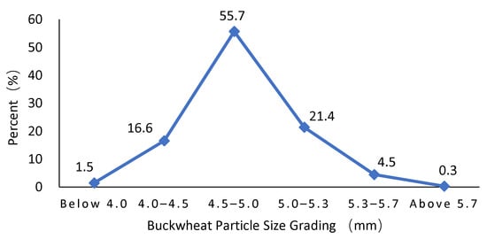
Figure 6.
Buckwheat particle size grading.
3.2. The Results from the Single-Factor Experiments
3.2.1. The Speed of the Grinding Disc
The results from the single-factor experiment for speed are shown in Figure 7. In the 4.0–4.5 mm particle size group, the whole-kernel rate reaches a maximal value of 28.6% at 12 r/min. The breakage rate exhibits a nonlinear response, significantly decreasing to 44.74% at 12 r/min, forming a minimum breakage plateau. The hulling rate remains stable at 75.08–88.07% (C.V = 5.37%, which is below the standard threshold of 10) [], indicating a weak correlation between the dehulling rate and the speed. In summary, considering the whole-kernel rate as the primary factor, at 12 r/min, the whole-kernel rate is highest, the breakage rate is relatively low, and the dehulling rate is high; thus, it is the optimal speed.
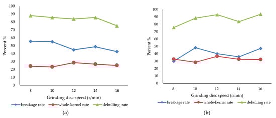
Figure 7.
Grinding disc speed experiment results: (a) 4.0–4.5 mm size group disc speed test; (b) 4.5–5.0 mm size group disc speed test.
The 4.5–5.0 mm group exhibits differentiated response mechanisms, with the whole-kernel rate peaking at 36.6% at 12 r/min and falling to 32.5% at 14 r/min; the crushing rate drops to lower levels at 12 r/min and 14 r/min, being 40.05% and 35.85%, respectively; the dehulling rate is 92.9% at 12 r/min and shows a significant inflection point at 14 r/min, decreasing to 83.5%. Further comparison of the two sets of data shows that, at 12 r/min, the whole-kernel rate is 12.62% higher than at 14 r/min, while the changes in the breakage rate and dehulling rate are similar, with both around 11%. Overall, the highest whole-kernel rate is obtained at 12 r/min, making it the optimal rotational speed.
This study confirms that, at a grinding disc speed of 12 r/min, synergistic optimization of dehulling efficiency and whole kernel rate can be achieved, providing a theoretical basis for the standardization of parameters for buckwheat dehulling equipment.
3.2.2. The Gap Between the Grinding Discs
For the case of small gaps, the experimental results are shown in Figure 8. In Figure 8a, for the particle size group of 4.0–4.5 mm, at a gap of 2.53 mm, the whole-kernel rate reaches a maximum of 32.93%, the dehulling rate is 71.54%, and the breakage rate is 29%. Although the dehulling rate is relatively low, the breakage rate is reduced by 52% compared to the 2.5 mm gap, indicating that the optimal gap for this particle size group is 2.53 mm. In Figure 8b for the 4.5–5.0 mm particle size group, at a gap of 2.8 mm, although the breakage rate is slightly higher at 30.33%, it achieves a peak whole-kernel rate of 37.5% and a dehulling rate of 79% through synergistic optimization. Comprehensive analysis suggests that the optimal gap for this particle size group is 2.8 mm. In Figure 8c for the 5.0–5.3 mm particle size group, a gap of 3.2 mm sees the whole-kernel rate at 46.6% and the dehulling rate at 85.9%, both reaching extrema simultaneously. The breakage rate maintains a similar trend to the dehulling rate, being 21.5% at 3.2 mm, which is slightly higher than at other gaps. Analyzing the three indicators, the whole-kernel rate and dehulling rate are significantly higher than at other gap sizes; thus, the optimal gap for this particle size group is 3.2 mm. In Figure 8d, with 5.3–5.7 mm for the particle size group, as the gap increases, the whole-kernel rate first rises and then falls, reaching its maximum value of 55.14% at a gap of 3.4 mm. Both the dehulling rate and breakage rate decrease with increasing gap size, with the breakage rate approaching a low level of 12.50% at a gap of 3.4 mm and a dehulling rate at 82.2%. Since the whole-kernel rate is maximized and the breakage rate is relatively low, the optimal gap between the grinding discs for this particle size group is 3.4 mm.
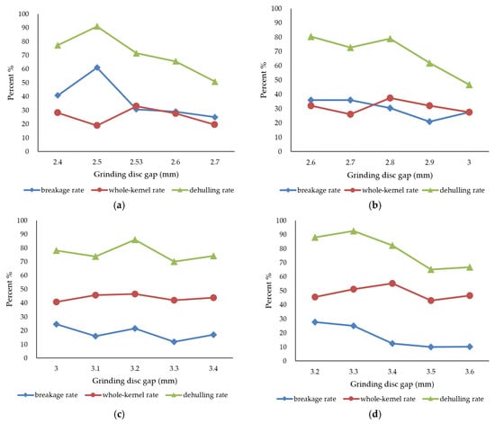
Figure 8.
Results from the small gap tests for: (a) the 4.0–4.5 mm size group grinding disc gap test; (b) the 4.5–5.0 mm size group grinding disc gap test; (c) the 5.0–5.3 mm size group grinding disc gap test; (d) the 5.3–5.7 mm size group grinding disc gap test.
Based on the above analysis, the following conclusions can be drawn from the small gap experiments:
- (1)
- There is a significant linear relationship between the disc gap and the grain particle size. The optimal hulling gaps for the four particle size groups of buckwheat grains of 4.0–4.5 mm, 4.5–5.0 mm, 5.0–5.3 mm, and 5.3–5.7 mm are 2.53 mm, 2.8 mm, 3.2 mm, and 3.4 mm, respectively.
- (2)
- From the experimental results, it can be observed that, as the dehulling gap increases, the whole-kernel rate for each particle size group initially increases and then decreases, while the broken rate shows a trend consistent with that of the dehulling rate.
In conclusion, this study provides a theoretical basis for the optimization of buckwheat dehulling equipment parameters.
For the case of large gaps, the core indicator of secondary cumulative whole-kernel rate is used for evaluation, and a dehulling rate of 100% is estimated. The buckwheat test with a particle size of 4.5–5.0 mm is selected, and the results are shown in Figure 9. When the gap is large compared to 3.3 mm, the grinding discs’ compressing and rubbing action on the buckwheat decreases, leading to a significant decline in dehulling rate and breakage rate; more than two passes are needed to improve the whole-kernel rate. At a gap of 3.3 mm, the secondary cumulative whole kernel rate is converted to 57.08%, at which point both dehulling efficiency and effectiveness can be considered; however, if the gap continues to be increased, multiple rounds of processing would be required, reducing production efficiency. This gap parameter can serve as a benchmark for orthogonal experiments, guiding the optimization of the buckwheat dehulling process with large gaps.
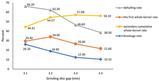
Figure 9.
Results from the large gap tests for the 4.5–5.0 mm particle size group.
3.3. The Results from the Orthogonal Experiments
3.3.1. Small Gap Orthogonal Experiment
For small gaps, the experimental factor level coding table is shown in Table 2, and the response surface optimization experimental design and results are shown in Table 3. The regression equations for the model were fitted based on the experimental results, as shown in Equations (14) and (15); a significance analysis of variance for whole kernel rate and dehulling rate was conducted, with the results shown in Table 4 and Table 5.
Y1 = 41.48 − 0.66 A + 0.11 B + 0.68 AB − 3.02 A2 − 1.25 B2
Y2 = 89.48 + 0.58 A − 0.11 B + 0.82 AB − 3.79 A2 − 1.60 B2
Table 2.
Coding table for the levels of factors in the small gap orthogonal experiment.
Table 3.
Design of and results from the orthogonal experiment for small gaps.
Table 4.
Variance analysis of the whole-kernel rate for small gaps.
Table 5.
Variance analysis of the dehulling rate for small gaps.
From the analysis in Table 4, it can be seen that the regression model for the whole-kernel rate is highly significant (p < 0.0001), and the lack of fit term is not significant (p = 0.1401 > 0.05), indicating that the model has very high importance and good fit. The correlation coefficient of the model R2 is 0.9781, and the adjusted R2 is 0.9625, which is close to R2, indicating sufficient accuracy and reliability of the model. In the model, the first-order term of the gap (A), the second-order term (A2), and the second-order term of the disc speed (B2) have highly significant effects (p < 0.01). In addition, the interaction term (AB) has a significant effect (p < 0.05), while the first-order term of the disc speed (B) has no significant effect. The experiments show that the gap has a nonlinear effect on the whole-kernel rate, and that there is a synergistic effect with the speed.
From analysis of Table 5, it can be seen that the regression model for the dehulling rate is highly significant (p < 0.0001), and the lack of fit term is not significant (p = 0.0815 > 0.05), indicating that the model has a good fit. R2 = 0.9865, Adj.R2 = 0.9769, and both values are close, verifying the accuracy and reliability of the model. In the model, the quadratic term of the gap between the grinding discs (A2) and the quadratic term of the grinding speed (B2) have a highly significant impact (p < 0.01), while the linear term of the gap (A) and the interaction term AB have a significant impact (p < 0.05). The linear term of the grinding speed (B) does not have a significant impact, confirming the dominant role of the gap on the dehulling rate.
From Table 4 and Table 5, it can be seen that the interaction between disc gap and disc speed (AB) is significant in the regression models for the whole-kernel rate and the dehulling rate with small gap. A response surface analysis was conducted, as shown in Figure 10. Both the whole-kernel rate and the dehulling rate initially increase and then decrease with increases in the disc gap and disc speed. Based on the steepness of the curves, a steeper slope indicates a greater influence of that factor on the response value. Therefore, Figure 10a,b both indicate that the variation in disc gap (A) has a greater effect on the response values than disc speed (B). The shape of the contour lines, which are elliptical, signifies the significance of the interaction term (AB) and indicates that both parameters need to be optimized in coordination.
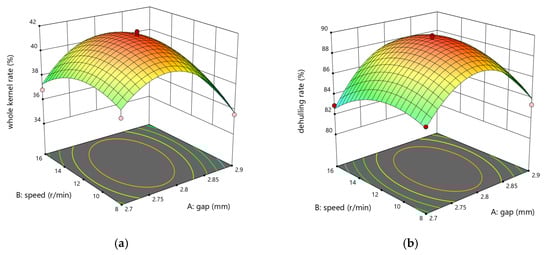
Figure 10.
Response surface analysis of a small gap: (a) the effect of interactive factors on the whole-kernel rate; (b) the effect of interactive factors on the dehulling rate: the elliptical contour indicates a significant interaction effect between the grinding gap (A) and the rotational speed (B).
To obtain the optimal working performance parameters of the dehulling machine with a small gap, the goal of maximizing whole-kernel rate and dehulling rate was set. The optimal parameters were determined to be a grinding disc gap of 2.856 mm and a rotation speed of 12.717 r/min. The optimal parameter combination was subjected to three repeated validation tests, with the results showing a whole-kernel rate of 38.03% and a predicted error of 5.41%; the dehulling rate was 89.9%, with a predicted error of 1.44%, indicating a small error, and the model prediction reliability was relatively high.
3.3.2. Large Gap Orthogonal Experiment
In order to better explore the effect of the gap between the grinding discs on the whole-kernel rate, a more reasonable production plan can be proposed for production. Therefore, based on the single-factor results of large gaps, the same method is used to construct a model to investigate the effects of grinding disc gap (A) and grinding disc rotation speed (B) on the whole-kernel rate (Y1) and the dehulling rate (Y2). The coding table for the experimental factor levels is shown in Table 6. The experimental design of and results for the response surface optimization are shown in Table 7. The regression fitting equations for large gaps are shown in Formulas (16) and (17), and the results from the variance significance analysis for the whole-kernel rate and dehulling rate are shown in Table 8 and Table 9.
Y1 = 31.54 − 0.96 A + 0.05 B − 0.71 AB − 3.58 A2 − 2.84 B2
Y2 = 55.54 − 1.64 A − 0.38 B + 3.39 AB − 5.56 A2 − 3.41 B2
Table 6.
Coding table for the levels of factors in the large gap orthogonal experiment.
Table 7.
Design of and results from the orthogonal experiment for large gaps.
Table 8.
Variance analysis of the whole-kernel rate for large gaps.
Table 9.
Variance analysis of the dehulling rate for large gaps.
The analysis in Table 8 indicates that the regression model for the whole-kernel rate is highly significant (p < 0.0001), while the lack of fit term is not significant (p = 0.0749 > 0.05), suggesting that the model is valid. R2 = 0.9929, Adj.R2 = 0.9879, and both values being close verifies the accuracy and reliability of the model. In the model, the first-order term for the gap between the grinding discs (A), the second-order term (A2), the second-order term for the grinding disc speed (B2), and the interaction term (AB) have a highly significant effect (p < 0.01), while the first-order term for the grinding disc speed (B) has no significant effect, indicating that the nonlinear effects are enhanced with larger gaps.
The analysis in Table 9 indicates that the regression model for the dehulling rate is highly significant (p < 0.0001), while the lack of fit is not significant (p = 0.1289 > 0.05), suggesting that the model has very high importance and good fit. R2 = 0.9555 and Adj.R2 = 0.9237, which is close to R2, indicating that the model is accurate and reliable. In the model, the second-order term of the gap between the grinding discs (A2), the second-order term of the grinding disc speed (B2), and the interaction term (AB) are extremely significant (p < 0.01), the first-order term of the gap (A)is significant (p < 0.05), while the first-order term of the grinding disc speed (B) is not significant.
According to Table 8 and Table 9, the disc gap × disc speed (AB) interaction in the regression models for whole-kernel rate and hull removal rate is highly significant with the large gap, as shown in the response surface analysis in Figure 11. These results indicate that the influence trend of disc gap (A) and disc speed (B) on the response value is consistent with that of the small gap. Based on the slope of the curves, it can be determined that the impact of the disc gap (A) on the response value is greater than that of disc speed (B). The elliptical shape of the contour lines indicates a significant interaction between the two factors. However, both the whole-kernel rate and the dehulling rate show a notable decrease compared to the small gap, indicating that further optimization of the re-dehulling strategy is necessary.
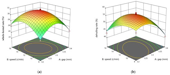
Figure 11.
Response surface analysis of the large gap: (a) the effect of interactive factors on the whole kernel rate; (b) the effect of interactive factors on the dehulling rate: the elliptical contour indicates a significant interaction effect between the grinding gap (A) and the rotational speed (B).
For optimization of the working parameters of the dehulling machine with a large gap, aiming to maximize the whole-kernel rate and dehulling rate, the optimal parameters obtained are a disc gap of 3.286 mm and a disc speed of 12.015 r/min. The validation test results show that the whole-kernel rate is 33.43%, with a prediction error of 8.86%; the dehulling rate is 59.8%, with a prediction error of 7.16%. The errors are within an acceptable range, indicating that the predictive model is reliable.
In conclusion, the disc gap has a significant impact on the dehulling effect of buckwheat, and there is a notable interaction effect between disc gap and disc speed. The predictive accuracy of the response surface is relatively high (R2 > 0.95). The optimized parameter combination can provide a technological basis for the dehulling of buckwheat with different particle sizes. The small gap scheme is suitable for high-efficiency production, while the large gap needs to be combined with multiple dehulling runs to improve the whole-kernel rate.
4. Discussion
4.1. The Impact of Buckwheat Grain Grading on Dehulling
Based on the single-factor experiments with the small grinding disc gap, a comparison of the whole-kernel rate, dehulling rate, and breakage rate with the optimal grinding disc gap for each particle size group was conducted, with the results shown in Figure 12. As the particle size increases, the dehulling rate and whole-kernel rate both rise simultaneously, while the breakage rate gradually decreases. This could be related to the classification of buckwheat particle sizes. In this experiment, the buckwheat in the 4–5 mm range has a particle size span of 0.5 mm, while the buckwheat in the 5–6 mm range has a particle size span of either 0.3 mm or 0.4 mm. The smaller the classification span, the more uniform the particles in the same size group, leading to greater consistency in force application, thereby ensuring improved dehulling efficiency and whole kernel rates. Therefore, in actual production, it is advisable to classify buckwheat into finer particle sizes, with an optimal span of 0.2–0.3 mm, to precisely match the grinding disc gap parameters and balance efficiency (dehulling rate) with quality (whole-kernel rate, low breakage rate).
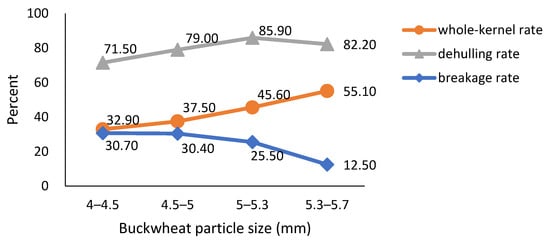
Figure 12.
Comparison of the best gap results for each particle size group.
4.2. The Impact of the Grinding Disc Gap on Dehulling
This experiment conducted an in-depth investigation into the gap between the discs, comparing the parameters and results optimized from two sets of orthogonal experiments with small and large gaps, as shown in Figure 13. From the figure, it can be observed that the first dehulling rate for the small gap is 89.90%, which is significantly higher than that for the large gap. The first whole-kernel rate shows a small difference compared to the first whole-kernel rate for the large gap. However, the dehulling rate for the large gap is relatively low. After a second dehulling, with the first dehulling rate of 89.90% as a baseline, the second cumulative whole-kernel rate can reach 50.26%, which is much higher than the first whole-kernel rate for the small gap. Therefore, in practical production, if the goal is to achieve a high single-pass dehulling rate and improve efficiency, while accepting a certain level of breakage, a small gap is preferred; if quality is the primary concern, a large gap is preferred, allowing for multiple rounds of re-dehulling to further refine the buckwheat kernels, improve the whole-kernel rate, and reduce the breakage rate.
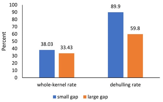
Figure 13.
Comparison of the optimal parameter results for small and large gaps.
In summary, our gap-adjustable, deep–shallow textured millstone achieved 32.9–55.1% whole-kernel rates, exceeding domestic double-disc (6QB-150, > 30%) and centrifugal (6P-400, 16.3%) dehullers. Unlike the imported Brown EBJ apparatus (~60%), which is unsuitable for domestic varieties, its 0–10 mm gap matches local cultivars. Additionally, our optimal parameter combinations (e.g., 2.859 mm gap for 38.03% whole-kernel rate in mass production, 3.288 mm gap with secondary dehulling for 50.26% cumulative rate) resolve the longstanding trade-off between dehulling efficiency and whole-kernel rate emphasized in literature, offering a practical solution for both high-volume and high-value production.
5. Conclusions
The design of the grinding disc-type buckwheat dehulling machine has been completed, which includes the upper and lower disc’s textural structure, gap adjustment device, and transmission system. The alternating structure of deep and shallow textures is conducive to improving the adaptability of the dehulling machine. The sliding angle of the grinding disc is set at 26°, preventing self-locking of buckwheat kernels and enabling their smooth discharge from the machine, thus ensuring continuous operation of the dehulling process.
Based on the buckwheat particle size grading results, single-factor experiments on the disc speed and dehulling gap have been completed. The results indicate that, for the disc speed, the optimal speed for buckwheat is determined to be 12 r/min. For the dehulling gap of the disc, using the whole-kernel rate as an indicator, the optimal disc gap for buckwheat with a grain size of 4.0–4.5 mm is 2.53 mm, with a whole-kernel rate of 32.9%, a dehulling rate of 71.5%, and a breakage rate of 29%; for buckwheat with a grain size of 4.5–5.0 mm, the optimal disc gap is 2.8 mm, with a whole-kernel rate of 37.5%, a dehulling rate of 79%, and a breakage rate of 30.3%; for buckwheat with a grain size of 5.0–5.3 mm, the optimal disc gap is 3.2 mm, with a whole-kernel rate of 45.6%, a dehulling rate of 85.9%, and a breakage rate of 21.5%; for buckwheat with a grain size of 5.3–5.7 mm, the optimal disc gap is 3.4 mm, with a whole-kernel rate of 55.1%, a dehulling rate of 82.2%, and a breakage rate of 12.5%. At different particle sizes, the whole-kernel rate reached over 30%, and as the particle size grading span decreased, the whole-kernel rate gradually increased, reaching a maximum of 55.1%, with simultaneous improvement in the dehulling rate. For the secondary cumulative whole-kernel rate, a single-factor experiment was conducted with a large gap between the grinding discs. The optimal grinding disc gap for a grain size of 4.5–5.0 mm is 3.3 mm, aiming for a dehulling rate of 100%, and the secondary cumulative whole-kernel rate after re-dehulling of buckwheat increased to 57.08%, with good dehulling effects.
An orthogonal experiment of the response surface with grinding disc speed and dehulling gap as factors was completed. The results show that, for buckwheat with a particle size of 4.5–5.0 mm, at small gaps, the optimal combination of operating parameters for the grinding disc is a gap of 2.859 mm and a grinding disc speed of 12.37 r/min, at which point the experimental dehulling rate reached 89.9%, and the whole-kernel rate was 38.03%. At large gaps, the optimal combination of operating parameters for the grinding disc is a gap of 3.288 mm and a grinding disc speed of 11.867 r/min, at which point the experimental dehulling rate was 59.8%, and the whole-kernel rate was 33.43%, with the converted whole-kernel rate after re-dehulling being 50.26%. In both cases, the gap between the grinding discs is an important influencing factor, and the interaction between the grinding disc rotation speed and the gap is significant. Therefore, it is particularly important to accurately control the optimal gap of the grinding discs while ensuring the best rotation speed. The whole-kernel rate and dehulling effect of both cases are quite good, but in actual production, the specific requirements should determine which gap to use. If the goal is to improve dehulling efficiency, a small gap can be chosen; if the goal is to improve the whole-kernel rate, a larger gap can be selected. This experiment also provides a more reasonable choice and basis for the practical production of buckwheat dehulling.
Existing studies have confirmed that uniform grain size is a key factor in improving dehulling performance. However, manual round-hole sieving is inefficient and suitable only for laboratory use. In the future, an online automatic grading system could be developed to sort buckwheat grains of different sizes in real time, narrowing the size range from the current 0.5 mm down to 0.2–0.3 mm. This system could be directly incorporated into the dehulling production line to achieve continuous grading–dehulling and eliminate the bottleneck caused by manual grading inefficiency.
Author Contributions
Conceptualization, N.Z.; methodology, N.Z.; software, N.Z.; validation, N.Z. and D.Z.; formal analysis, W.L.; investigation, L.L.; resources, D.Z.; data curation, W.L. and L.L.; writing—original draft preparation, N.Z.; writing—review and editing, N.Z. and D.Z.; project administration, N.Z. All authors have read and agreed to the published version of the manuscript.
Funding
This research was funded by Fundamental Research Program of Shanxi Province (No. 20210302124372), Central guidance for local scientific and technological development funding projects (No. YDZJSX20231C009), and the Youth Science and Technology Innovation Project of Shanxi Agricultural University (No. 2018014).
Institutional Review Board Statement
Not applicable.
Data Availability Statement
Data are contained within the article.
Conflicts of Interest
The authors declare no conflicts of interest.
References
- Song, C.; Ma, C.; Xiang, D. Variations in Accumulation of Lignin and Cellulose and Metabolic Changes in Seed Hull Provide Insight into Dehulling Characteristic of Tartary Buckwheat Seeds. Int. J. Mol. Sci. 2019, 20, 524. [Google Scholar] [CrossRef]
- Sun, J.; Guo, Y.; Yang, Z.; Cui, Q.; Wu, X.; Zhang, Y. Experiment study on biomechanical properties of buckwheat grain and viscoelastic properties of buckwheat powder. Trans. Chin. Soc. Agric. 2018, 34, 287–298. [Google Scholar]
- Fan, R.; Cui, Q.; Zhang, Y.; Lu, Q. Analysis and calibration of parameters of buckwheat grain based on the stacking experiment. Inmateh 2021, 64, 467–476. [Google Scholar] [CrossRef]
- Vieites-Álvarez, Y.; Reigosa, M.J.; Sánchez-Moreiras, A.M. A decade of advances in the study of buckwheat for organic farming and agroecology (2013–2023). Front. Plant Sci. 2024, 15, 1354672. [Google Scholar] [CrossRef]
- Zhou, M.; Tang, Y.; Deng, X.; Ruan, C.; Kreft, I.; Tang, Y.; Wu, Y. Overview of Buckwheat Resources in the World. In Buckwheat Germplasm in the World; Elsevier: Amsterdam, The Netherlands, 2018; pp. 1–7. [Google Scholar] [CrossRef]
- Raina, K.; Kumari, R.; Thakur, P.; Sharma, R.; Chaudhary, A. Buckwheat: An Underutilized Himalayan Crop with Multifaceted Nutraceutical Benefits. Recent Adv. Food Nutr. Agric. 2025, 16, 266–281. [Google Scholar] [CrossRef] [PubMed]
- Kharchenko, Y.; Buculei, A.; Chornyi, V.; Sharan, A. Influence of technical and technological parameters on the barley dehulling process. Ukr. Food J. 2022, 11, 542–557. [Google Scholar] [CrossRef]
- Zhen, J.; Chen, W.; Gao, H. Study on Hulling Characteristics of Buckwheat Huller. INMATHE Agric. Eng. 2022, 66, 239–246. [Google Scholar] [CrossRef]
- Lachuga, Y.F.; Ibyatov, R.I.; Ziganshin, B.G.; Shogenov, Y.H.; Dmitriev, A.V. Simulation of the Grain Trajectory along Working Bodies of the Pneumatic Mechanical Dehuller. Russ. Agric. Sci. 2020, 46, 534–538. [Google Scholar] [CrossRef]
- Zhang, Y.; Yang, T.; Yue, D.; Shao, X.; Chen, Y. Cold plasma-assisted buckwheat grain dehulling and farinographical properties of dehulled buckwheat flour. J. Cereal Sci. 2023, 112, 103716. [Google Scholar] [CrossRef]
- Jha, R.; Zhang, K.; He, Y.; Mendler-Drienyovszki, N.; Magyar-Tábori, K.; Quinet, M.; Germ, M.; Kreft, I.; Meglič, V.; Ikeda, K.; et al. Global Nutritional Challenges and Opportunities: Buckwheat, a Potential Bridge between Nutrient Deficiency and Food Security. Trends Food Sci. Technol. 2024, 145, 104365. [Google Scholar] [CrossRef]
- Zhong, H.; Yang, X.; She, Y.; Shi, B.; Xiao, S.; Wang, A.; Chen, Z. Effects of Different Dehulling Methods on Physical and Chemical Properties of Tartary Buckwheat Flour. Starch-Stärke 2025, 77, 2400082. [Google Scholar] [CrossRef]
- Yang, W.; Duan, H.; Yu, K.; Hou, S.; Kang, Y.; Wang, X.; Hao, J.; Liu, L.; Zhang, Y.; Luo, L.; et al. Integrative Dissection of Lignin Composition in Tartary Buckwheat Seed Hulls for Enhanced Dehulling Efficiency. Adv. Sci. 2024, 11, 2400916. [Google Scholar] [CrossRef]
- Liu, G.; Jiang, Y.; Du, W. Current situation and prospects of buckwheat hull removal equipment. South Chin. Agri. 2020, 14, 145–146. [Google Scholar]
- Chen, W.; Du, W.; Zheng, D.H.; Liu, G. Experimental study and parameter analysis on buckwheat huller. J. Chin. Agric. Univ. 2017, 22, 107–114. [Google Scholar]
- Fan, B.; Ruan, H.; Jin, T.; Du, W. Analysis of the hulling mechanism for the buckwheat and improvement of texture of hulling unit. Trans. Chin Soc. Agric Eng. 2024, 40, 64–74. [Google Scholar]
- Solanki, C.; Mridula, D.; Aleksha Kudos, S.K.; Gupta, R.K. Buckwheat Dehuller and Optimization of Dehulling Parameters. Int. J. Curr. Microbiol. App. Sci. 2018, 7, 1041–1052. [Google Scholar] [CrossRef]
- Upreti, M.; Norbu, K.; Phuntsho, U.; Norbu, J.; Tshering, D. AMC-made Impeller-type buckwheat dehuller and optimization of impeller speed. Bhut. J. Agric. 2022, 5, 172–182. [Google Scholar] [CrossRef]
- Liang, B.; Pei, E.; Wang, X.; Ju, M.; Zheng, D. Design and test of 6P-400 buckwheat peeling machine. Agric. Eng. 2022, 12, 117–124. [Google Scholar]
- Zhu, X.; Fan, W.; Li, Z.; Guo, W. Test and development of a non-thermal tartary buckwheat huller. J. Chin. Agric. Univ. 2017, 22, 146–155. [Google Scholar]
- Chen, W.; Du, W.; Liu, C. The pressure properties of tartary buckwheat before and after steaming. J. Agric. Mech. Res. 2015, 37, 194–197. [Google Scholar]
- Verma, K.C.; Verma, S.K.; Tamta, P.; Joshi, R.; Joshi, N. Roasting Induced Phytoconstituents Variability and Effect of Temperature on Soluble Proteins of Buckwheat Cultivars. Food Meas. 2024, 18, 8445–8456. [Google Scholar] [CrossRef]
- China Agricultural Mechanization Science Research Institute. Agricultural Machinery Design Handbook, 1st ed.; China Agricultural Science and Technology Press: Beijing, China, 2007. [Google Scholar]
- Ghorbani, S.; Hoseinie, S.H.; Ghasemi, E.; Sherizadeh, T.; Wanhainen, C. A New Rock Hardness Classification System Based on Portable Dynamic Testing. Bull Eng. Geol. Environ. 2022, 81, 179. [Google Scholar] [CrossRef]
- Liu, C.; Du, W.L.; Quan, Y.J.; Xing, K.; Han, H. Influence of Sieve Structural Parameters on Sieving of Shelled Buckwheat. Absol. Med. Response 2014, 915–916, 978–984. [Google Scholar] [CrossRef]
- Samoichuk, K.; Fuchadzhy, N.; Kovalyov, A.; Hutsol, T.; Horetska, I.; Semenyshena, R.; Yermakov, S.; Rozkosz, A. Design and efficiency of a string hulling machine for buckwheat. Agric. Eng. 2024, 28, 119–135. [Google Scholar] [CrossRef]
- Fan, R. Experimental Study on Cleaning Kinetic Characteristics of Buckwheat Crops Harvested by Machinery. Ph.D. Thesis, Shanxi Agricultural University, Jinzhong, China, 2022. [Google Scholar]
Disclaimer/Publisher’s Note: The statements, opinions and data contained in all publications are solely those of the individual author(s) and contributor(s) and not of MDPI and/or the editor(s). MDPI and/or the editor(s) disclaim responsibility for any injury to people or property resulting from any ideas, methods, instructions or products referred to in the content. |
© 2025 by the authors. Licensee MDPI, Basel, Switzerland. This article is an open access article distributed under the terms and conditions of the Creative Commons Attribution (CC BY) license (https://creativecommons.org/licenses/by/4.0/).