Abstract
Stalk composite pipe (SCP), a novel product used for subsurface irrigation, is primarily composed of crop stalks, soil, and water. In subsurface SCP irrigation (SSI), comprehending the effects of burial furrow parameters on soil water movement is critical. However, the precise effects are not known. Here, we aimed to assess the effects of varying burial furrow dimensions, including widths of 15, 20, and 25 cm, depths of 10, 15, and 20 cm, and backfilling-soil bulk densities of 1.1, 1.2, and 1.3 g cm−3, on wetted distance and soil water movement. We conducted an indoor soil bin experiment and numerical simulation using HYDRUS-2D in 2020–2021 in Zhengzhou City, Northern China. Wider burial furrows resulted in increased wetted distance and soil water content, ultimately leading to greater effect in a horizontal direction. In the horizontal profile, the average soil water content of the SSI treatments, which used burial furrow widths of 15, 20, and 25 cm, were 1.121, 1.230, and 1.280 times higher, respectively, than those of CK. The burial furrow depth had minimal effect on the wetted distance, whereas adjusting the burial furrow depth primarily affected the saturation depth. The speed of wetting-front migration was affected by the backfilling-soil bulk density. For a given soil and crop, it is advisable to determine first the burial furrow width and backfilling-soil bulk density. Subsequently, the burial furrow depth should be established based on the distribution of the crop’s roots. Our findings offer a scientific basis for using SSI.
1. Introduction
Water scarcity in China has reached critical levels due to a combination of global climate change and rapid population growth. This crisis has had a profound effect on the agricultural sector, the largest consumer of water in China [1,2]. In recent years, China’s annual shortage of irrigation water has exceeded 3 billion m³ [3]. Furthermore, the distribution of water resources in China is highly uneven, and climate change is exacerbating droughts in agriculture. Therefore, improving the efficiency of farmland irrigation is imperative to address water scarcity and ensure food security. At present, the utilization coefficient of irrigation water in China is only 0.568, far below 0.8, the value in developed countries [4,5].
To alleviate agricultural water scarcity and ensure food security, the Chinese government has implemented policies aimed at promoting the development of water-saving irrigation technologies since 2005. In the No. 1 Central Document of 2011, it was proposed that CNY 4 trillion would be invested in the construction and development of water conservancy projects between 2010 and 2020 [6,7]. The State Council promulgated the “Regulations on Farmland Water Conservancy” in 2016, in which high-efficiency water saving was one principle for practicing agricultural water conservation. Promoting water-saving irrigation technologies was also encouraged [8]. In the “Implementation Plan for Adding 6.67 million hm2 of High-efficiency and Water-saving Irrigation Areas during the 13th Five-Year Plan Period” issued by the Ministry of Water Resources in 2017, the amount of land under drip irrigation was specifically stated as 2.61 million hm2 [9]. According to the requirements stipulated in the Central Document No. 1 of 2021, the MWR and the National Development and Reform Commission jointly issued the “Implementation Plan for Major Agricultural Water Saving and Water Supply Projects during the 14th Five-Year Plan”, which stated that water-saving irrigation technologies should be strongly supported [10]. These policies propelled China to embark upon unprecedented reforms in modernizing agricultural irrigation, leading to the widespread adoption of various high-efficiency water-saving irrigation technologies.
Subsurface drip irrigation (SDI) is a water-efficient irrigation technology that uses buried drip pipes [11,12]. This methodology prevents surface evaporation and aids soil moisture conservation, resulting in significant advantages for water conservation and yield enhancement [13,14,15]. Compared to surface drip irrigation, SDI can reduce water usage by 23% while maintaining the same citrus yield [16]. Furthermore, research has shown that SDI has the potential to increase wheat yield by 12% and improve water-use efficiency by 20% compared to flood irrigation [17]. In Northern China, SDI yielded significantly higher winter wheat and summer maize crops compared to surface drip irrigation, partial root zone irrigation, and flood irrigation technologies [18]. Nevertheless, two issues affect the application of SDI: outlet clogging resulting from mud suction and root invasion [19,20,21,22] and difficulties in recycling SDI pipes [23]. These issues have impeded the widespread adoption of SDI.
Crop stalk production in China amounts to about 800 million tons annually, which represents approximately 25% of global stalk production [24]. The rise in grain production has led to an increase in stalk production, resulting in an oversupply of stalks. This has further led to resource waste and environmental pollution due to the improper use of these stalks [25,26,27]. To address this issue, China has implemented policies to encourage the use of stalks as fertilizer, feed, fuel, and base and raw materials [28]. Among these, fertilizer constitutes roughly 60% of stalk usage [28,29]. Returning stalks to farmland as fertilizer is the primary approach, enhancing soil structure, increasing soil nutrient levels, and facilitating species diversity within the soil microbial community [30,31]. The decomposition of stalks increases crop yields by 4.025–10.57% and water-use efficiency by 2.87–12.25% as they release essential nutrients such as nitrogen, phosphorus, and potassium for crop growth [4]. Furthermore, returning stalks to farmlands has boosted surface soil organic carbon reserves in Northern China by 11% 14 years after their introduction [32], highlighting their importance in carbon reduction and sequestration in agriculture.
However, direct return of stalks poses several challenges. First, there is a low seed germination rate due to the large number of shallowly buried stalks that create a poor soil–stalk mixture [33,34]. Second, microorganisms require specific amounts of carbon, nitrogen, and moisture to decompose the stalks, which results in competition with crops for water and fertilizer [31,35]. Finally, returning crop stalks directly to the soil increases the risk of pests and diseases, as they may contain viruses and insect eggs [36,37]. These negative impacts have hindered the promotion and application of the practice in farmland.
To address these issues, Wu, et al. [38] created the stalk composite pipe (SCP), a novel subsurface irrigation product that integrates the characteristics of stalks and SDI. Fresh maize stalks, soil, and water are used to make SCP, which excels in water delivery and infiltration [39]. Subsurface SCP irrigation (SSI) refers to the use of SCPs for subsurface irrigation. A previous study established the optimal stalk–soil–water mix proportion for SCPs [38]. Indoor experiments showed a linear correlation between working pressure and SCP infiltration rate [40]. In field experiments, the effects of stalk ratio and pipe length on hydraulic properties, including outflow, infiltration rate, and irrigation uniformity, were investigated. The results showed that a stalk ratio of 5% to 7% results in optimal outflow and irrigation uniformity [41].
In SSI, the parameters of burial furrows are significant factors that affect the movement of soil water. However, no comprehensive study has yet assessed the precise effects of these parameters on soil water movement. In this study, using experimental data from indoor soil bin experiments, we analyzed the effects of burial furrow width, depth, and backfilling-soil bulk density on soil water movement by employing the HYDRUS-2D model. Our study provides a theoretical foundation for promoting and applying SSI.
2. Materials and Methods
2.1. Laboratory Experiment
Laboratory experiments were conducted at Henan Key Laboratory of Water-Saving Agriculture, North China University of Water Resources and Electric Power, Zhengzhou City, Henan Province, North China Plain (34°72′ N, 113°65′ E). The physical properties of the experimental soil are presented in Table 1. The experimental equipment comprised a soil bin, SCP, Mariotte bottle, and an adjustable height bracket (Figure 1a). The experimental soil bin comprised acrylic plates (100 cm in length, 100 cm in width, and 100 cm in height). The experimental soil was passed through a 5 mm sieve, air-dried, and placed at every 10 cm in the soil bin to achieve a bulk density of 1.35 g cm−3. The surface of each repacked layer was roughened to obtain homogeneous hydraulic properties. The initial soil water content of the air-dried soil was 0.09 cm−3. The SCP was an irrigation pipe (28 mm inner diameter and 60 mm outer diameter) with combined features of water transfer and infiltration, invented by our group (Figure 1b). At present, there is only one diameter for SCPs. The Mariotte bottle acted as the SCP irrigator.

Table 1.
Physical properties of the experimental soil.
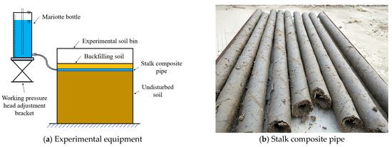
Figure 1.
Diagram of subsurface SCP irrigation system.
Our previous findings suggested that the hydraulic performance of SCPs was the best when stalks were added at 5~7% [41]. In this study, the SCPs were composed of 7%, 71%, and 22% of stalk, soil, and water, respectively. The flow rate of the SCP was 11.486 L/(h⸱m) under conditions of a 50 cm working pressure head. The irrigation time for each experimental treatment was 3 h and the irrigation water volume was about 34 L.
Following the water supply, the wetted distance (vertically downward and horizontal) was recorded at 3, 15, 30, 60, 120, 180, 240, 300, and 720 min under a Cartesian coordinate system centered at the SCP. The soil water content was measured using the oven dry method. After irrigation (24 h), soil samples were collected at depths of 0, 10, 20, 30, and 40 cm from the soil surface and laterally at 10, 20, and 30 cm from the SCP (Figure 2).
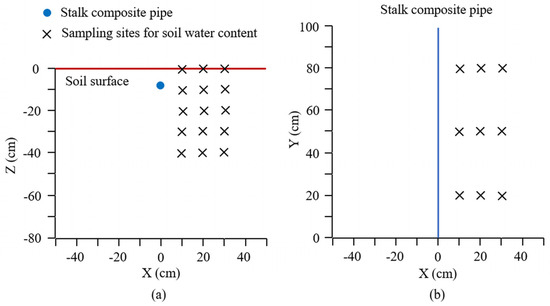
Figure 2.
Diagram of sampling sites for soil water content. (a) represents sampling sites in the vertical soil profile, and (b) represents sampling sites in the horizontal soil profile.
2.2. Treatments
A soil bin experiment was conducted to investigate the effect of burial furrow parameters on soil water content under SSI. Burial furrow parameters, including width, depth, and backfilling-soil bulk density, were examined (Table 2). A control group (CK) that received moistube irrigation was established. Each treatment was replicated three times.
Table 2.
Detailes of treatments on burial furrow parameters.
2.3. Methods
2.3.1. Experimental Design
All treatments were simulated using HYDRUS-2D software (https://www.pc-progress.com/en/Default.aspx, accessed on 3 January 2024 ). Because the flow of water under SSI was a line source, soil water movement during the infiltration and redistribution periods could be considered a two-dimensional problem. Assuming water flow in a homogenous and isotropic soil, the following Richards equation is the governing equation:
where q is the volumetric water content (cm3 cm−3), t is the time (min), h is the soil water pressure head (cm), r is the horizontal coordinate (cm), z is the vertical coordinate (cm), and K is the unsaturated hydraulic conductivity (cm min−1).
The soil hydraulic properties were modeled using the van Genuchten equation.
where qs is the saturated water content (cm3 cm−3), qr is the residual water content (cm3 cm−3), Ks is the saturated hydraulic conductivity (cm min−1); Se is the effective saturation, and a, m, n, and l are the empirical coefficients that affect the shape parameters of the hydraulic functions.
The observed values—horizontal and vertically downward wetted distances and soil water content at the observation points—for treatments of T4, T6, and T8 were used for comparative analysis against the simulated values. The parameters of the characteristic curve were then repeatedly calibrated until the appropriate parameters were obtained. The hydraulic properties of the soils were initially estimated using Neural Network Prediction. The hydraulic properties of the soils considered in the HYDRUS simulations are presented in Table 3.
Table 3.
Hydraulic properties of soils considered in the HYDRUS simulations.
2.3.2. Transport Domain: Initial and Boundary Conditions
The geometry module in HYDRUS was used to construct the simulation domain. The transport domain (50 cm wide and 80 cm deep) for all treatments was considered axisymmetric around a vertical axis, so we used one side for the simulation (Figure 3). It was discretized into 1626 nodes and 3112 2D elements. In all simulations, the bottom boundary of the transport domain and both sides of the vertical boundaries were defined as no-flux boundaries, whereas the upper boundary of the transport domain was described as an atmospheric boundary. The SCP was located on the left vertical boundary of the transport domain, and it was described as a constant head boundary during the infiltration period. The SCP boundary was changed to a no-flux boundary during the redistribution period.
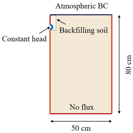
Figure 3.
Boundary conditions.
2.3.3. Model Accuracy Test
The simulated model was evaluated using the coefficient of determination (R2), Nash–Sutcliffe efficiency (NSE), root mean square error (RMSE), and RMSE–observation standard deviation ratio (RSR) [42,43].
where Oi is the observed values, Si is the simulated values, O is the mean of the observed values, S is the mean of the simulated values, and N is the total number of observed values.
Table 4.
The evaluation criteria of model performance.
3. Results
3.1. Model Accuracy
The model parameters were calibrated and verified using the experimental data of T4, T6, and T8. Comparison of the simulated and observed wetted distances under different treatments is shown in Figure 4. It showed that the points, whose coordinates were the simulated and observed values of the wetted distances, were all distributed near the 1:1 line. Thus, the simulated results agreed with the experimental results. Then, R2, NSE, and RSR were calculated for horizontal and vertically downward wetted distances and soil water content (SWC), respectively. The model simulated results are presented in Table 5. Based on the evaluation criteria, R2 was “very good” (>0.9 in all cases), whereas NSE and RSR ranged from “very good” to “good” (except for the horizontal wetted distance of T8). The observed and simulated values were consistent. Therefore, the SSI model (based on the HYDRUS model) was highly accurate and reliable in simulating the soil water movement.
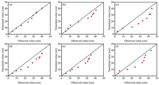
Figure 4.
Simulated and observed values of the wetted distance. (a–c) represent horizontal wetted distances of T4, T6, and T8, respectively; (d–f) represent vertical wetted distances of T4, T6, and T8, respectively.
Table 5.
Statistical analysis of the observed and simulated values.
3.2. Effect of Burial Furrow Width on Soil Water Movement
3.2.1. Effect of Burial Furrow Width on Wetted Distance
The wetted distances in the horizontal and vertically downward directions for various burial furrow widths are depicted in Figure 5. The wetted distance expanded as the burial furrow width increased. Furthermore, with an increase in irrigation time, the disparity between the wetted distances under varying burial furrow widths grew. As the burial furrow width increased, the vertical wetted distance did not considerably change during the water infiltration period. However, it increased during the water redistribution period. The disparities in the vertically downward wetted distance during water redistribution were attributed to the varying amounts of water held in distinct burial furrow widths.
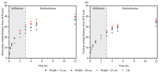
Figure 5.
Wetted distance for different burial furrow widths. (a) represents the horizontal direction and (b) represents downward direction.
After 3 h of irrigation, the horizontal wetted distance increased by 14.34%, 25.78%, and 35.49%, whereas the vertical wetted distance increased by 14.34%, 20.37%, and 20.37%, compared to CK, when the burial furrow width was 15, 20, and 25 cm, respectively. During the water redistribution period, which occurred after 12 h, the wetted distance for burial furrows with widths of 15, 20, and 25 cm increased by 13.06%, 21.26%, and 28.45% in the horizontal direction, respectively. In the vertical direction, the wetted distance increased by 10.86%, 16.47%, and 22.18%, respectively, when compared with CK. The results indicated that using a wider burial furrow improved the speed of wetting-front migration, resulting in longer wetted distances, particularly in the horizontal direction.
3.2.2. Effect of Burial Furrow Width on Soil Water Distribution
The soil water content was measured after 24 h of irrigation. The characteristics of soil water distribution along the SCP’s horizontal and vertical profiles are shown in Figure 6. A greater burial furrow width meant a larger wetted range and higher soil saturation near the SCP, and vice versa. In addition, the SWC under SSI was significantly greater than that of CK. In the horizontal profile, the average SWC of CK was 19.33%. The average SWCs of the SSI treatments using different burial furrow widths of 15, 20, and 25 cm were 1.121, 1.230, and 1.280 times higher than that of CK, respectively. In the vertical profile, the average SWC of CK was 18.39%. The corresponding ratios in the vertical profile were 1.080, 1.117, and 1.141 times higher, respectively. These results indicated that increasing burial furrow width could increase the SWC in the horizontal direction. It is worth noting that soil water content changed abruptly at the pipe–furrow–soil junction. The non-continuity in soil water content was caused by bulk density. In this study, the bulk density of the SCP, backfilling soil, and undisturbed soil are 1.45 g cm−3, 1.1–1.3 g cm−3, and 1.35 g cm−3, respectively. The saturated water content of the soil is related to the bulk density, i.e., the lower the bulk density, the higher the saturated water content.
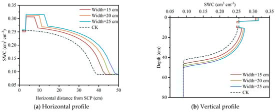
Figure 6.
Soil water distribution along the SCP’s horizontal and vertical profiles under different burial furrow widths.
The SWC distribution of horizontal and vertical profiles located at varying distances from the SCP is shown in Figure 7. The wetted areas under SSI were significantly larger than those under moistube irrigation. Furthermore, the greater burial furrow width meant a larger wetted range and higher soil saturation near the SCP, and vice versa. With increasing burial furrow width, the SWC increased more in the horizontal direction than that in the vertical direction. This indicated that increasing the burial furrow width mainly increased the SWC and wetted range in the horizontal direction.
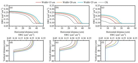
Figure 7.
Soil water distribution in horizontal and vertical profiles located at varying distances from the SCP, with different burial furrow widths. (a–c) Horizontal profile at (a) 20 cm, (b) 30 cm, and (c) 40 cm from the surface. (d–f) Vertical profile at (d) 20 cm, (e) 30 cm, and (f) 40 cm from the SCP.
3.3. Effect of Burial Furrow Depth on Soil Water Movement
3.3.1. Effect of Burial Furrow Depth on Wetted Distance
The wetted distances (horizontal and vertically downward) were measured at various heights of burial furrow depths and their characteristics are shown in Figure 8. The wetted distance for SSI was greater than that for CK. After 3 h of irrigation, compared with the 20 cm burial furrow depth, the horizontal wetted distance under the 10 cm and 15 cm depths increased by 4.57 and 1.58 cm, respectively, whereas the vertical wetted distance increased by 2.2 and 1.1 cm, respectively. During the water redistribution period, after 12 h, the horizontal and vertical wetted distances were observed under different burial furrow depths. Results indicated that the horizontal wetted distances at 10 cm and 15 cm depths were greater than that of the 20 cm depth by 2.93 and 1.75 cm, respectively. Likewise, the vertical wetted distances were greater by 3.73 and 0.98 cm, respectively. Although the wetted distance decreased as the burial furrow depth increased, the reduction was insignificant. Consequently, the burial furrow depth had a minor effect on the wetted distance.
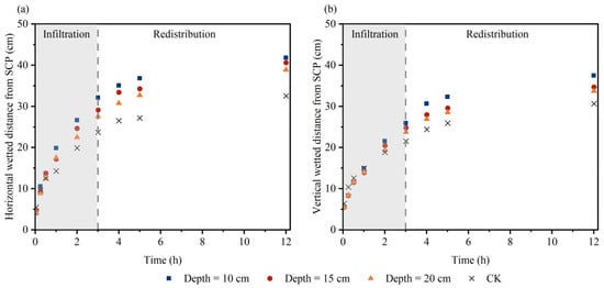
Figure 8.
Wetted distances for different burial furrow depths. (a) represents the horizontal direction and (b) represents downward direction.
3.3.2. Effect of Burial Furrow Depth on Soil Water Distribution
The soil water distribution characteristics of the SCP’s vertical and horizontal profiles at different burial furrow depths are depicted in Figure 9. Following 24 h of irrigation, there was minimal variance in the average SWC in the horizontal profile within the range of 25 cm from SCP. Beyond 25 cm from the SCP, SWC decreased with increasing burial furrow depth. In the horizontal profile, the wetted distance reached the surface for all three burial furrow depths. In the vertically downward direction of the soil column, the depth of soil saturation increased as the burial furrow depth increased. In the horizontal profile, the average SWCs of the three burial furrow depths were 1.280, 1.273, and 1.259 times greater than that of CK. In the vertical profile, the ratios were 1.141, 1.218, and 1.289. Therefore, the burial furrow depth had a minor effect on SWC in the horizontal direction, primarily affecting the saturation depth.
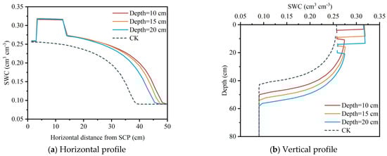
Figure 9.
Soil water distribution along the SCP’s horizontal and vertical profiles under different burial furrow depths.
Under different burial furrow depths, the characteristics of soil water distribution at horizontal and vertical profiles located at varying distances from the SCP are shown in Figure 10. No significant change was observed in the mean SWC in areas within 20 cm from the surface. Beyond 20 cm from the surface, the SWC increased with increasing burial furrow depth. However, the changed in SWC between 20 and 30 cm from the surface were small. Increasing burial furrow depths had a greater effect on the vertical wetted depth but a smaller effect on the horizontal soil water content.
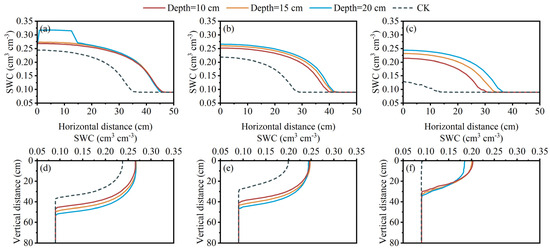
Figure 10.
Soil water distribution at horizontal and vertical profiles located at varying distances from the SCP, with different burial furrow depths. (a–c) Horizontal profile at (a) 20 cm, (b) 30 cm, and (c) 40 cm from the surface. (d–f) Vertical profile at (d) 20 cm, (e) 30 cm, and (f) 40 cm from the SCP.
3.4. Effect of Backfilling-Soil Bulk Density on Soil Water Movement
3.4.1. Effect of Backfilling-Soil Bulk Density on Wetted Distance
Changes in the wetted distance (both horizontally and vertically) over time are presented in Figure 11. After irrigating for three hours, the horizontal wetted distance saw increases of 14.56%, 10.72%, and 0.04% as the backfilling-soil bulk density increased from 1.1 to 1.3 g cm−3 when compared to the control (CK). Similarly, the vertical wetted distance saw increases of 20.37%, 13.41%, and 0% under the same conditions. During the water redistribution period, after 12 h, the horizontal wetted distance increased by 13.06%, 8.94%, and 3.23% and the vertical wetted distance increased by 16.47%, 10.86%, and 0% when the backfilling-soil bulk density reached 1.1, 1.2, and 1.3 g cm−3, respectively, compared to CK. The results demonstrate that the wetted distance declined as the bulk density of the backfilling soil increased. This effect was more prominent in the vertical direction compared to the horizontal direction. The backfilling-soil bulk density primarily affected the migration speed of the wetting front. Specifically, a higher backfilling-soil bulk density resulted in a slower migration speed of the wetting front.
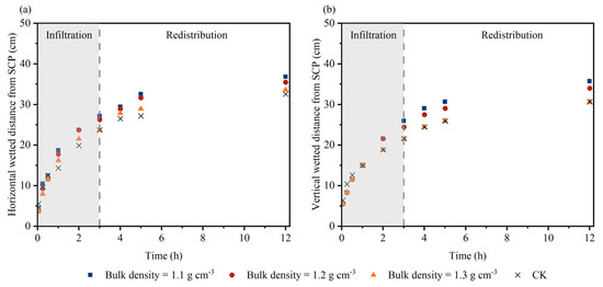
Figure 11.
Wetted distance for different backfilling-soil bulk densities. (a) represents the horizontal direction and (b) represents downward direction.
3.4.2. Effect of Backfilling-Soil Bulk Density on Soil Water Distribution
The soil water distribution characteristics along the horizontal and vertical profiles of the SCP under distinct backfilling-soil bulk densities are presented in Figure 12. The average SWCs for backfilling-soil bulk density values of 1.1, 1.2, and 1.3 g cm−3 in the vertical profile were 1.230-, 1.154-, and 1.065-fold greater than that in CK. In the horizontal profile, these values were 1.117-, 1.065-, and 1.009-fold higher, respectively. The results suggest that soil water distribution in both horizontal and vertical profiles is affected by the backfilling-soil bulk density. As the backfilling-soil bulk density increased, the SWC in both profiles decreased.
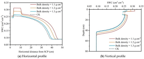
Figure 12.
Soil water distribution along the SCP’s horizontal and vertical profiles under different backfilling-soil bulk densities.
Figure 13 illustrates soil water distribution characteristics at different distances from the SCP under different backfilling-soil bulk densities. The SWC decreased with an increased bulk density of the backfilling soil at depths of 20, 30, and 40 cm in the vertical profile. In the horizontal profile, the SWC at depths of 20, 30, and 40 cm from the SCP decreased with an increasing bulk density.
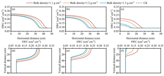
Figure 13.
Soil water distribution at horizontal and vertical profiles located at varying distances from the SCP, with different backfilling-soil bulk densities. (a–c) Horizontal profile at (a) 20 cm, (b) 30 cm, and (c) 40 cm from the surface. (d–f) Vertical profile at (d) 20 cm, (e) 30 cm, and (f) 40 cm from the SCP.
4. Discussion
4.1. Effect of Burial Furrow Parameters on Soil Water Movement under Subsurface SCP Irrigation
Burial furrow parameters play a crucial role in the application of SSI. Based on our simulations, we discovered that the horizontal wetted distance under SSI was greater than that under moistube irrigation and SDI (Figure 5 and Figure 6). This led to a reduction in the time taken for adjacent wetting fronts to meet, causing an improvement in irrigation uniformity horizontally. Thus, SSI proves to be a better option for flat sown crops, such as wheat, as compared to moistube irrigation. For moistube irrigation, the depth at which the moistube pipe is buried influences the time needed for the wetting front to reach the upper and lower boundaries. However, it does not affect the shape of the wetted area [46]. In the current study, the wetted depth and shape were affected by the depth of the burial furrow due to the synergistic effect of the pipe, furrow, and soil [39]. After water from SCP infiltrated, it rapidly infiltrated into the backfilling soil but moved slowly into the undisturbed soil, leading to the initial filling of the burial furrow with water.
Unlike the irrigation pipes used in moistube and SDI systems, the SCPs used in SSI comprise maize stalks, soil, and water. As an irrigation tool, SCPs contain numerous minuscule cracks along their pipe walls which allow water to infiltrate through. This water can then infiltrate through the backfilling soil in the burial furrow and the undisturbed soil in the field, ultimately reaching the crop root zone due to the water potential difference. Because the properties of SCP are like the surrounding soil, water could infiltrate any part of the pipe walls. In contrast, moistube and SDI pipes release water only from their fixed outlet holes, making them prone to clogging and low irrigation uniformity [47,48]. Thus, SSI is a more efficient option that largely avoids these issues.
However, for moistube irrigation and SDI, it may be necessary to remove the pipes after the crops’ life cycle [49]. However, SCPs possess characteristics similar to soil and can be easily incorporated back into the field using rotary tillage, eliminating the need for pipe retrieval and thus making SSI more adaptable and flexible than traditional methods.
4.2. The practical Applicability of Subsurface Stalk Composite Pipe Irrigation
Our group studied the outflow rate and irrigation uniformity at different pressure heads (25 cm, 50 cm, 80 cm). We found that subsurface stalk composite pipe irrigation is suitable for low-pressure conditions. The SCP inlet is easily broken at a pressure head of 80 cm and, thus, pipe surges occur, thereby resulting in poor irrigation uniformity. This is mainly due to the SCP composition: a stalk, soil, and water mixture; after extrusion, the SCP’s own material properties make the pipe pressure capacity low. When the pressure head is 50 cm, pipe surges are avoided, and the flow rate and irrigation uniformity meet the irrigation needs. In this study, in order to compare the soil water movement under subsurface stalk composite pipe irrigation and moistube irrigation, we set the pressure head at 50 cm for all treatments. Under conventional subsurface irrigation techniques, the working pressure is above 1 m. Therefore, water taken from the water source must be pressurized before it can be transported to the delivery pipes net. In contrast, SCPs can fulfill water delivery and irrigation functions at a low pressure of 50 cm, indicating that subsurface stalk composite pipe irrigation has an energy-saving effect.
Field experiment results showed that winter wheat yield under SSI irrigation increased by 5.11% and water-use efficiency increased by 8.81% compared to subsurface drip irrigation. The lifetime of SCPs is harmonized with crop growth. Stalk decomposition increases C–N content of soil and improves soil quality, thus promoting crop cultivation and yield. Owing to the fact that crop seeds are mostly sown in the soil surface layer, a too-deep burial depth is not beneficial to the surface wetting effect and is not conducive to crop emergence. Therefore, the burial depth of straw composite pipes should consider the surface wetting effect.
4.3. Limitations of this Study
To examine the effects of burial furrow width and depth as well as backfilling-soil bulk density on wetted distance and soil water movement, an indoor soil bin experiment and simulation using the HYDRUS-2D model were conducted using sandy loam soil. The present study found there was high consistency between the observed and simulated values for the wetted distance and the SWC, demonstrating the accuracy of the HYDRUS-2D model in simulating the soil water movement under SSI. However, Figure 4 shows that the simulated values of the HYDRUS-2D model were lower than the observed values. The primary reason for the discrepancy is that the numerical simulation assumes perfect water infiltration conditions, meaning that the SCP has no cracks and all water infiltrates through it. However, in reality, SCPs contain cracks that permit water to flow out directly, which reduces the time required for water to infiltrate out of SCPs. Dimensional analysis techniques can be used to estimate the wetted width and depth [50]. In the practical application of SSI, we can try to apply the method to determine suitable burial furrow parameters for crops.
Field experiments are vital in assessing the efficacy of SSI parameters. Hence, upcoming research on SSI must encompass field experiments to measure the water-saving advantages linked with varied SSI parameters. Furthermore, it is crucial to ascertain if SSI enhances the irrigation water utilization coefficient, crop yield, and crop quality relative to conventional water-saving irrigation techniques. When optimizing SSI parameters, it is crucial to consider factors such as soil type, crop type, working pressure, and irrigation time, as they have a significant effect on outcomes. To promote the widespread implementation of SSI technology, it is imperative to design parameter sets customized to accommodate varying types of crops and soil.
5. Conclusions
In this study, we conducted an indoor soil bin experiment and used HYDRUS-2D numerical simulation to analyze soil water movement under different burial furrow parameters. A precise SSI soil water movement model was developed through HYDRUS-2D software, which accurately simulated water infiltration during SCP irrigation. An increased burial furrow width resulted in a greater wetted distance and SWC, particularly in the horizontal direction. The burial furrow depth had minimal effect on the wetted distance, but adjusting it affected the wetted depth and shape. A greater burial furrow depth corresponded to a higher SWC in the vertical profile beneath the furrow. The backfilling-soil bulk density affected the migration speed of wetting fronts. An increased backfilling-soil bulk density resulted in a decrease in wetting-front migration speed, a shorter wetted distance, and a smaller SWC. To achieve optimal results for a specific soil type, it is recommended to first determine the necessary burial furrow width and backfilling-soil bulk density for the desired wetting width. After this, determine the burial furrow depth based on the crop root distribution.
Author Contributions
Conceptualization, F.W., X.F. and S.Z.; methodology, F.W., X.F., D.W. and S.Z.; software, X.F., D.W. and L.L.; validation, F.W., X.F. and X.L.; formal analysis and investigation, F.W., X.F., X.L., D.W., S.Z. and L.L.; resources, F.W., X.L. and S.Z.; data curation and writing—original draft, F.W., X.F., X.L., D.W., S.Z. and L.L.; writing—review and editing, F.W., X.F., X.L., D.W., S.Z. and L.L.; visualization, F.W., X.F. and S.Z.; supervision, F.W., X.L. and S.Z.; project administration, F.W. and S.Z.; funding acquisition, F.W. and S.Z. All authors have read and agreed to the published version of the manuscript.
Funding
This research was funded by the National Natural Science Foundation of China (51979108).
Data Availability Statement
Data recorded in the current study are available in all tables and figures of the manuscript.
Acknowledgments
We would like to thank the editor and the expert reviewers for their detailed comments and suggestion for the manuscript. These were very useful to hopefully improving the quality of the manuscript.
Conflicts of Interest
The authors declare no conflicts of interest.
References
- Wang, L.; Wu, W.; Xiao, J.; Huang, Q.; Hu, Y. Effects of different drip irrigation modes on water use efficiency of pear trees in Northern China. Agric. Water Manag. 2021, 245, 106660. [Google Scholar] [CrossRef]
- Wang, L.; Zhu, G.; Qiu, D.; Liu, Y.; Zhao, K.; Sang, L.; Zhang, Z.; Sun, Z.; Yong, L.; Jiao, Y. The use of stable isotopes to determine optimal application of irrigation-water to a maize crop. Plant Soil 2023, 482, 679–696. [Google Scholar] [CrossRef]
- Wang, H.; Wang, L.; Yang, G.; Jia, L.; Yao, Y.; Zhang, Y. Agricultural water resource in china and strategic measures for its efficient utilization. Strateg. Study CAE 2018, 20, 9–15. [Google Scholar] [CrossRef]
- Zhang, H.; Yan, H.; Hui, X.; Zhao, H.; Wang, W.; Guo, H. Experimental and numerical simulations of soil water movement under mobile drip irrigation system. Trans. Chin. Soc. Agric. Eng. 2023, 39, 158–168. [Google Scholar]
- MWR. MWR (Ministry of Water Resources, PRC), China Water Resources Bulletin 2021; China Water and Power Press: Beijing, China, 2021. [Google Scholar]
- Liu, J.; Yang, W. Water Sustainability for China and Beyond. Science 2012, 337, 649–650. [Google Scholar] [CrossRef] [PubMed]
- PRC. No. 1 Central Document” for 2011. Available online: http://www.lswz.gov.cn/html/zmhd/wmfw/2018-06/14/content_234975.shtml (accessed on 3 January 2024).
- PRC. Farmland Water Conservancy Regulations, Order No. 669 of the State Council of the People’s Republic of China. Available online: https://www.gov.cn/gongbao/content/2016/content_5082977.htm (accessed on 3 January 2024).
- MWR. The Ministry of Water Resources and Other Five Ministries and Commissions Jointly Issued the Implementation Plan of Adding 100 Million Mu of High-Efficiency Water-Saving Irrigation Area during the 13th Five-Year Plan Period. Available online: http://nssd.mwr.gov.cn/tzgg/201901/t20190115_1096692.html (accessed on 3 January 2024).
- MWR. Implementation Plan for Major Agricultural Water-Saving and Water Supply Projects in the 14th Five-Year Plan. Available online: https://www.gov.cn/xinwen/2021-08/16/content_5631540.htm (accessed on 3 January 2024).
- Petit, J.; Mas García, S.; Molle, B.; Héran, D.; Ait-Mouheb, N.; Bendoula, R. Detection and monitoring of drip irrigation clogging using absorbance spectroscopy coupled with multivariate analysis. Biosyst. Eng. 2023, 235, 1–14. [Google Scholar] [CrossRef]
- Qiu, X.; Chen, G.; Wang, H.; Wang, C.; Wang, J. Vertical optimisation of tooth shape to improve the anti-clogging performance of emitters in drip irrigation systems. Biosyst. Eng. 2023, 233, 193–203. [Google Scholar] [CrossRef]
- Wang, H.; Wang, N.; Quan, H.; Zhang, F.; Fan, J.; Feng, H.; Cheng, M.; Liao, Z.; Wang, X.; Xiang, Y. Yield and water productivity of crops, vegetables and fruits under subsurface drip irrigation: A global meta-analysis. Agric. Water Manag. 2022, 269, 107645. [Google Scholar] [CrossRef]
- Gao, Y.; Yang, L.; Shen, X.; Li, X.; Sun, J.; Duan, A.; Wu, L. Winter wheat with subsurface drip irrigation (SDI): Crop coefficients, water-use estimates, and effects of SDI on grain yield and water use efficiency. Agric. Water Manag. 2014, 146, 1–10. [Google Scholar] [CrossRef]
- Camp, C.R. Subsurface drip irrigation: A review. Trans. Am. Soc. Agric. Eng. 1998, 41, 1353–1367. [Google Scholar] [CrossRef]
- Martínez-Gimeno, M.A.; Bonet, L.; Provenzano, G.; Badal, E.; Intrigliolo, D.S.; Ballester, C. Assessment of yield and water productivity of clementine trees under surface and subsurface drip irrigation. Agric. Water Manag. 2018, 206, 209–216. [Google Scholar] [CrossRef]
- Fang, Q.; Zhang, X.; Shao, L.; Chen, S.; Sun, H. Assessing the performance of different irrigation systems on winter wheat under limited water supply. Agric. Water Manag. 2018, 196, 133–143. [Google Scholar] [CrossRef]
- Zhang, H.; Liang, Q.; Peng, Z.; Zhao, Y.; Tan, Y.; Zhang, X.; Bol, R. Response of greenhouse gases emissions and yields to irrigation and straw practices in wheat-maize cropping system. Agric. Water Manag. 2023, 282, 108281. [Google Scholar] [CrossRef]
- Wu, F. Soil Water Movement and System Design Parameters under Subsurface Drip. Ph.D. Thesis, Northwest A & F University, Xianyang, China, 2010. [Google Scholar]
- Pei, Y.; Li, Y.; Liu, Y.; Zhou, B.; Shi, Z.; Jiang, Y. Eight emitters clogging characteristics and its suitability under on-site reclaimed water drip irrigation. Irrig. Sci. 2014, 32, 141–157. [Google Scholar] [CrossRef]
- Liu, Z.; Hou, P.; Zha, Y.; Muhammad, T.; Li, Y. Salinity threshold of desalinated saline water used for drip irrigating: The perspective of emitter clogging. J. Clean. Prod. 2022, 361, 132143. [Google Scholar] [CrossRef]
- Song, P.; Feng, G.; Brooks, J.; Zhou, B.; Zhou, H.; Zhao, Z.; Li, Y. Environmental risk of chlorine-controlled clogging in drip irrigation system using reclaimed water: The perspective of soil health. J. Clean. Prod. 2019, 232, 1452–1464. [Google Scholar] [CrossRef]
- Lamm, F.; Colaizzi, P.; Sorensen, R.; Bordovsky, J.; Dougherty, M.; Balkcom, K.; Zaccaria, D.; Bali, K.; Rudnick, D.; Peters, R. A 2020 Vision of Subsurface Drip Irrigation in the U.S. Trans. ASABE 2021, 64, 1319–1343. [Google Scholar] [CrossRef]
- Ji, L.-Q. An assessment of agricultural residue resources for liquid biofuel production in China. Renew. Sustain. Energy Rev. 2015, 44, 561–575. [Google Scholar] [CrossRef]
- Khalid, A.; Khushnood, R.A.; Ali Memon, S. Pyrolysis as an alternate to open burning of crop residue and scrap tires: Greenhouse emissions assessment and mechanical performance investigation in concrete. J. Clean. Prod. 2022, 365, 132688. [Google Scholar] [CrossRef]
- Seglah, P.A.; Wang, Y.; Wang, H.; Bi, Y.; Zhou, K.; Wang, Y.; Wang, H.; Feng, X. Crop straw utilization and field burning in Northern region of Ghana. J. Clean. Prod. 2020, 261, 121191. [Google Scholar] [CrossRef]
- Sun, J.; Peng, H.; Chen, J.; Wang, X.; Wei, M.; Li, W.; Yang, L.; Zhang, Q.; Wang, W.; Mellouki, A. An estimation of CO2 emission via agricultural crop residue open field burning in China from 1996 to 2013. J. Clean. Prod. 2016, 112, 2625–2631. [Google Scholar] [CrossRef]
- Xu, J.; Liu, Z.; Dai, J. Environmental and economic trade-off-based approaches towards urban household waste and crop straw disposal for biogas power generation project—A case study from China. J. Clean. Prod. 2021, 319, 128620. [Google Scholar] [CrossRef]
- Wang, J.; Tang, H.; Wang, J. Comprehensive utilization status and development analysis of crop straw resource in NortheastNortheast China. Trans. Chin. Soc. Agric. Mach. 2017, 48, 1–21. [Google Scholar]
- Zhou, Y.; Zhang, Y.; Tian, D.; Mu, Y. The influence of straw returning on N2O emissions from a maize-wheat field in the North China Plain. Sci. Total Environ. 2017, 584–585, 935–941. [Google Scholar] [CrossRef] [PubMed]
- Guan, Y.; Wu, M.; Che, S.; Yuan, S.; Yang, X.; Li, S.; Tian, P.; Wu, L.; Yang, M.; Wu, Z. Effects of Continuous Straw Returning on Soil Functional Microorganisms and Microbial Communities. J. Microbiol. 2023, 61, 49–62. [Google Scholar] [CrossRef] [PubMed]
- Chen, H.; Hou, R.; Gong, Y.; Li, H.; Fan, M.; Kuzyakov, Y. Effects of 11 years of conservation tillage on soil organic matter fractions in wheat monoculture in Loess Plateau of China. Soil Tillage Res. 2009, 106, 85–94. [Google Scholar] [CrossRef]
- Dai, X.; Li, Y.; Ouyang, Z.; Wang, H.; Wilson, G.V. Organic manure as an alternative to crop residues for no-tillage wheat–maize systems in North China Plain. Field Crops Res. 2013, 149, 141–148. [Google Scholar] [CrossRef]
- Ren, S.; Guo, B.; Wu, X.; Zhang, L.; Ji, M.; Wang, J. Winter wheat planted area monitoring and yield modeling using MODIS data in the Huang-Huai-Hai Plain, China. Comput. Electron. Agric. 2021, 182, 106049. [Google Scholar] [CrossRef]
- Yevdokimov, I.; Gattinger, A.; Buegger, F.; Munch, J.C.; Schloter, M. Changes in microbial community structure in soil as a result of different amounts of nitrogen fertilization. Biol. Fertil. Soils 2008, 44, 1103–1106. [Google Scholar] [CrossRef]
- Yu, F.; Yuxuan, C.; Huang, X.; Shi, J.; Xu, J.; He, Y. Does straw returning affect the root rot disease of crops in soil? A systematic review and meta-analysis. J. Environ. Manag. 2023, 336, 117673. [Google Scholar] [CrossRef] [PubMed]
- Sun, M.; Xu, X.; Wang, C.; Bai, Y.; Fu, C.; Zhang, L.; Fu, R.; Wang, Y. Environmental burdens of the comprehensive utilization of straw: Wheat straw utilization from a life-cycle perspective. J. Clean. Prod. 2020, 259, 120702. [Google Scholar] [CrossRef]
- Wu, F.; Wang, F.; Zai, S.; Chu, Y. Development and infiltration performance of corn straw composite infiltration irrigation pipe. Trans. Chin. Soc. Agric. Eng. 2019, 35, 98–104. [Google Scholar]
- Zai, S.; Xu, X.; Wu, F.; Chu, Y.; Wang, F. R&D of straw composite pipe as a new utilization of crop straw. Hydro Sci. Cold Zone Eng. 2020, 3, 79–84. [Google Scholar]
- Wu, F.; Liu, S.; Zai, S.; Wang, H.; Mou, Y.; Luo, X.; Zhang, M. Water permeability of stalk composite pipe under the free flow. Yellow River 2022, 44, 152–156. [Google Scholar]
- Wu, F.; Chu, Y.; Zai, S.; Wang, F.; Liu, S. Preliminary study on hydraulic performance of straw composite pipe. Agric. Res. Arid. Areas 2020, 38, 51–57. [Google Scholar]
- Naglič, B.; Kechavarzi, C.; Coulon, F.; Pintar, M. Numerical investigation of the influence of texture, surface drip emitter discharge rate and initial soil moisture condition on wetting pattern size. Irrig. Sci. 2014, 32, 421–436. [Google Scholar] [CrossRef]
- Phogat, V.; Mahadevan, M.; Skewes, M.; Cox, J.W. Modelling soil water and salt dynamics under pulsed and continuous surface drip irrigation of almond and implications of system design. Irrig. Sci. 2012, 30, 315–333. [Google Scholar] [CrossRef]
- Bannayan, M.; Hoogenboom, G. Using pattern recognition for estimating cultivar coefficients of a crop simulation model. Field Crops Res. 2009, 111, 290–302. [Google Scholar] [CrossRef]
- Wang, C.; Ye, J.; Zhai, Y.; Kurexi, W.; Xing, D.; Feng, G.; Zhang, Q.; Zhang, Z. Dynamics of Moistube discharge, soil-water redistribution and wetting morphology in response to regulated working pressure heads. Agric. Water Manag. 2023, 282, 108285. [Google Scholar] [CrossRef]
- Qi, W.; Zhang, Z.; Wang, C.; Huang, M.; Liu, C.; Chen, Y. Model construction and simulation of soil water movement under Moistube irrigation based on water potential difference-driven outflow mechanism. J. Hydraul. Eng. 2021, 52, 1091–1102. [Google Scholar] [CrossRef]
- Petit, J.; Ait-Mouheb, N.; Mas García, S.; Metz, M.; Molle, B.; Bendoula, R. Potential of visible/near infrared spectroscopy coupled with chemometric methods for discriminating and estimating the thickness of clogging in drip-irrigation. Biosyst. Eng. 2021, 209, 246–255. [Google Scholar] [CrossRef]
- Kanda, E.K.; Senzanje, A.; Mabhaudhi, T. Soil water dynamics under Moistube irrigation. Phys. Chem. Earth Parts A/B/C 2020, 115, 102836. [Google Scholar] [CrossRef]
- Dirwai, T.L.; Mabhaudhi, T.; Kanda, E.K.; Senzanje, A. Moistube irrigation technology development, adoption and future prospects: A systematic scoping review. Heliyon 2021, 7, e06213. [Google Scholar] [CrossRef] [PubMed]
- Mirzaei, F.; Hatami, M.; Mousazadeh, F.; Zhang, C.; Tang, H. A Simple Model to Estimate Wetted Soil Volume from the Trickle by Use of the Dimensional Analysis Technique. In Advances in Water Resources and Hydraulic Engineering; Springer: Berlin/Heidelberg, Germany, 2009; pp. 345–352. [Google Scholar]
Disclaimer/Publisher’s Note: The statements, opinions and data contained in all publications are solely those of the individual author(s) and contributor(s) and not of MDPI and/or the editor(s). MDPI and/or the editor(s) disclaim responsibility for any injury to people or property resulting from any ideas, methods, instructions or products referred to in the content. |
© 2024 by the authors. Licensee MDPI, Basel, Switzerland. This article is an open access article distributed under the terms and conditions of the Creative Commons Attribution (CC BY) license (https://creativecommons.org/licenses/by/4.0/).