Abstract
In this paper, we propose an optical transmission system of 128 quadrature amplitude modulation for dense wavelength division multiplexing. In such a system, Gaussian optical filtering is used to get an appropriate photonic carrier. Theoretical analysis and simulation computation show that the modulated multi-carrier photonic signals with the wavelength spacing of 0.7 nm can transmit for over 80 km with the standard single mode fiber. Using digital signal processing algorithms to compensate the transmission impairments, the transmission rate of the single-carrier photonic signal can reach up to 904 Gbps and the spectral efficiency of the transmission can reach up to 10.33 bps/Hz. When this technology is applied to a dense wavelength division multiplexing system with N channels, the huge message capacity of N × 904 Gbps can be realized. Furthermore, we find that the bit error rate and the error vector magnitude are similarly influenced by the optical signal-to-noise ratio and the bandwidth of the Gaussian optical filter. The influence presents mostly a synchronization trend with the change of the optical signal-to-noise ratio and the bandwidth of Gaussian optical filter.
1. Introduction
With the rapid development of the Internet of Things, mobile internet, and cloud computing, massive data of Petabyte (1015 bytes) is generated every day. The mass data makes the capacity of the backbone transmission networks increase rapidly. The optical networks with ultra-large capacity shoulder the fundamental service-transmission function of the backbone transmission networks. The sustained multiplication of the bandwidth requires higher capacity for the backbone transmission networks. The transmission systems with large capacity and high bandwidth become the development direction of future optical networks. Consequently, upgrading the transmission capacities of the backbone networks with the technique of dense wavelength division multiplexing (DWDM) on a large scale is imperative. One of the key techniques is to enhance the transmission capacity of a single wavelength. Major network operators around the world have initiated experimental tests and engineering verification of single-carrier optical fiber communication system with a rate of 400 Gbps. Currently, the transmission rate of a single wavelength is evolving from 100 Gpbs to 400 Gbps. Analyzing the core mechanisms and solving the key problems of single-wavelength optical fiber communication system with 400+ Gbps has become a recent focus in academia and industry [1,2,3,4,5,6,7]. In 2013, Bell laboratories reported a dual-carrier transmission system with the transmission distance of 320 km; the code-type of the transmission system was 64 quadrature amplitude modulation (QAM) format; and the capacity was up to 1.5 Tbps [8]. In 2014, Bell laboratories reported a multi-carrier transmission system with the single-channel rate of 1 Tbps again; the code-type of the system was 16QAM; the transmission distance was 480 km; and the spectral efficiency of the system was 5 bps/Hz [9]. Compared with optical communications with direct-detection, coherent optical communications [10,11,12,13,14,15] have the advantages of high receiving sensitivity and anti-polarization dispersion. In addition, the coherent detection can support M-ary modulation format and effectively utilize the bandwidth of the spectrum. Consequently, the technique of coherent optical communication is widely used in DWDM systems.
By analyzing the latest research in this field [1,2,3,6,8,9], we find that: (1) when the channel spacing is less than 50 GHz in a DWDM system, the cost of the array waveguide grating (AWG) and the difficulty of the production engineering will be greatly increased, and the interference between adjacent channels will be very serious; (2) the ratio of the transmission speed of a single wavelength to the spacing between two adjacent channels is relatively small, that is to say, the utilization efficiency of the spectrum is low; and (3) the coherent modulation and coherent detection are the core techniques in DWDM systems. For these reasons, we combine high-order coherent modulation with Gaussian optical filtering in an optical transmission system, and a DWDM system with ultra-high-speed and large capacity is realized. In this DWDM system, the two adjacent wavelengths spacing is 0.7 nm, the transmission rate of the single-wavelength is 904 Gbps, and the spectral efficiency is 10.33 bps/Hz. We also analyze the transmission performances of the DWDM system from the angles of the optical signal-to-noise ratio (OSNR) and the bandwidth of Gaussian optical filter (GOF).
2. Pulse Shaping
The processing procedure of a modulated photonic carrier with the modulation format of 128QAM which is gotten by using Gaussian optical filtering on an optical shaping is given in Figure 1.
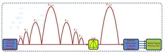
Figure 1.
Pulse shaping for a photonic carrier (GOF: Gaussian Optical Filter; QAM: Quadrature Amplitude Modulation).
The ultra-high-speed photonic carrier transmission with the modulation format of 128QAM is achieved by using optical phase dual-arm modulation with four differential signals, which are converted by series-to-parallel. In order to make it easy to understand, one of the photonic carriers with 128QAM based on optical phase dual-arm modulation is theoretically analyzed. The angular frequency of the continuous laser-carrier in the 128QAM photonic transmitter is , and then, the continuous laser-carrier can be described by:
where is the amplitude of the optical field output from the carrier-laser. is modulated by and , which are output from 128QAM sequence generator via the dual port Mach-Zehnder modulator (DPMZM) in the coherent 128QAM photonic transmitter. The expression of the modulated signal output from the DPMZM can be further described by [16,17]:
where is the output of the laser-wave; is the insertion loss; and are the input electrical voltages for the upper modulator arm and the lower modulator arm, respectively; and are the configurations for the bias voltage 1 and bias voltage 2 of the DPMZM; is the switching modulation voltage; is the switching bias voltage; γ is the optical power splitting ratio of the both Y-branch waveguides; and there is a definite functional relationship between and the extinction ratio [17]. The extinction ratio (ER) of the DPMZM is 20 dB; the parameters of and are configured as 3 V; the setting of is 5 dB; and the settings of and are 0 V.
From [16,17], and Equation (2), we can derive the following:
where and are the special constants, which can be described by:
where and Vs2(t) are two-channel electrical signals output from 128QAM sequence generator; the numerical values of them are 0 or 1 at every moment, which can be regarded as constants.
From Equation (3), by the method of the Bessel function expansion, we can see that a modulated photonic-carrier signal contains many photonic harmonic-waves, and the angular frequencies of the harmonic-waves are (n = 0, ±1, ±2, ±3, ±4, ±5, and more). In other words, the angular frequency space of the adjacent harmonic-wave is . We can also see that the power of the central photonic harmonic-wave is maximum, and the powers of the others photonic harmonic-waves decrease gradually with the increase of n, and each photonic harmonic-wave contains the same ultra-high-speed modulation information.
Lastly, we can obtain the central photonic harmonic-wave from the output of the coherent 128QAM photonic transmitter via an appropriate optical filtering, where the suitable filter is a Gaussian optical filter. The functional model of the optical filter can be described by:
where is insertion loss, is center frequency, is bandwidth, and is filtering order.
From Figure 1, it can be seen that only the bandwidth of the central carrier-wave is kept. The more modulated photonic carrier-waves can be transmitted over the limited bandwidth of a certain specific wavelengths; the more available wavelength channels can be realized in a DWDM transmission system.
3. System Architecture and Transceiver Units
The ultra-high-speed DWDM transmission system with a large capacity based on 128QAM and Gaussian optical filtering is shown in Figure 2.
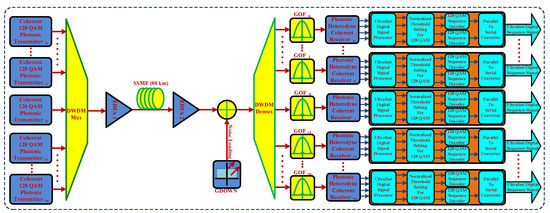
Figure 2.
Setup used for ultra-high-speed transmission (DWDM: Dense Wavelength Division Multiplexing; GOF: Gaussian Optical Filter; QAM: Quadrature Amplitude Modulation; SSMF: Standard Single Mode Fiber; EDFA: Erbium Doped Fiber Amplifier; GDOWN: Gaussian Distributed Optical White Noise).
The multi-carrier signals with the adjacent wavelength space of 0.7 nm produced by multiple coherent photonic transmitters with the same modulation format of 128QAM are multiplexed into an SSMF via the DWDM-Mux; the multiplexed multiple carriers are amplified by EDFA 1; the amplified optical signals are transmitted over 80 km with the SSMF, amplified again via EDFA 2, de-multiplexed via DWDM-Demux, mixed with the Gaussian distributed optical white noise (GDOWN), and filtered by GOFs successively; The filtered photonic signals are then successively processed via the photonic heterodyne coherent receivers, ultra-fast digital signal processors (UDSP), normalized threshold setting for 128QAM (NTS-128QAM), 128QAM sequence decoders (128QAM-SD), and parallel-to-serial converters (PTSC). Finally, the useful information is demodulated and the ultra-fast digital sequence signals are obtained. The main parameters of the critical components and key modules are shown in Table 1.

Table 1.
Configuration of the parameters in the DWDM transmission system.
The functional block diagram of the coherent photonic transmitter is shown in Figure 3. The ultra-fast digital sequence signal is divided into two signals by the serial-to-parallel converter (STPC); the two signals are identically processed, and the up one is used to illustrate the modulation process of the ultra-fast signal. It is divided into two signals again via the 128QAM sequence generator 1, and these two signals are processed by M-ary pulse generator 1 and M-ary pulse generator 2, thus obtaining the two M-ary pulse signals. The two M-ary pulse signals are processed identically, we use the up one to illustrate the process. The two signals output from the M-ary pulse generator 1 are processed as bias via the EB 1 and EB 2. The two biased signals modulate a light-wave produced by a CW laser via LiNb-DPMZ modulator 1. The generating methods of the light-waves in LiNb-DPMZ modulator 1, LiNb-DPMZ modulator 2, LiNb-DPMZ modulator 3, and LiNb-DPMZ modulator 4 are same. We use the light-wave which is input into the LiNb-DPMZ modulator 1, for example, to illustrate the modulating process. The light-wave produced by the CW Laser 1 with the center frequency of (1550 ± 0.7 × N) nm and the line-width of 100 Hz is divided into two light-waves via PS 1, and the two divided light-waves are processed with the same way. These two light-waves are generated by the light-wave output from PS 1 via optical coupler 3, which are input into the LiNb-DPMZ modulator 1 and LiNb-DPMZ modulator 2 as modulated laser light-waves, respectively. The modulated photonic carrier-wave signal output from the LiNb-DPZM modulator 2 is processed via an optical phase shifter at 90°, and the photonic carrier-wave is coupled with the output of the LiNb-DPMZ modulator 1 via optical coupler 5. The modulated photonic carrier-wave output from the LiNb-DPMZ modulator 4 is processed via an optical phase shifter at 90°, and the photonic carrier-wave is coupled with the output of LiNb-DPMZ modulator 3 via optical coupler 6. The output of coupler 5 is combined with the output of coupler 6 via PC 1. The output of the coherent photonic transmitter with the modulation format of 128QAM are then obtained. It is noted that the parameters of the LiNb-DPMZ modulator used above are configured as, extinction ratio: 20 dB, switching RF voltage: 3 V, switching bias voltage: 3 V, insertion loss: 5 dB, modulation voltage 1:2 V, bias voltage 1:0 V, bias voltage 2:0 V, and modulation voltage 2:2 V.
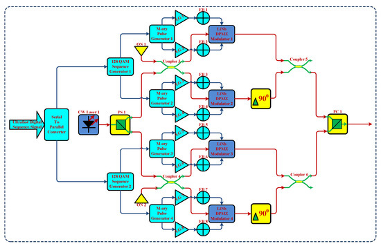
Figure 3.
Setup for coherent photonic transmitter (LiNb-DPMZ Modulator: LiNb-Dual Port Mach-Zehnder Modulator; CW Laser: Continuous Wave Laser; EB: Electrical Bias; PS: Polarization Splitter; EG: Electrical Gain; ON: Optical Null; PC: Polarization Combiner).
The function block diagram of the photonic heterodyne coherent receiver is shown in Figure 4. The photonic signals transmitted from the coherent photonic transmitter are split into two paths by PS 3 in the photonic heterodyne coherent receiver. The two photonic signals are processed with the same way. One of the two photonic signals is split into two new photonic signals via coupler 7; the new two photonic signals are processed with the same method. One of the new two photonic signals is input into coupler 11; and the other one is input into coupler 12. The continuous laser-wave emitted from CW Laser 2 with the center frequency of (1550 ± 0.7 × N) nm and the line-width of 100 Hz is split into two paths via PS 2, and these two photonic signals are processed with the same method. One of the two photonic signals is split into two new photonic signals, again via coupler 8. One of the two new photonic signals is processed via the optical phase shifter at 90°, and one is input into coupler 12, while the other is input into the coupler 11.
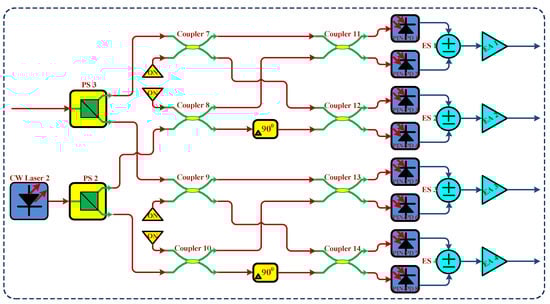
Figure 4.
Setup for photonic heterodyne coherent receiver (PIN-PD: positive-intrinsic-negative photodiode; ES: Electrical Subtractor; PS: Polarization Splitter; EA: Electrical Amplifier).
The two photonic signals output from coupler 11 are detected by two positive intrinsic negative photodiodes (PIN-PD 1 and the PIN-PD 2); two detected signals are processed by ES 1, and then amplified via EA 1. It is noted that the processing procedures and processing methods of coupler 11, coupler 12, coupler 13, and coupler 14 are same.
Figure 5 shows the flow diagram of the algorithm design for the UDSP which is used for the compensation of transmission impairments and signal reconstruction. The noise is removed by a Bessel filter with 3rd order. The sampled signal is re-sampled at a rate of . A cubic interpolation is utilized to adapt the waveform of the sampled signal to the resampling rate. The first and sampled signals are used for re-sampling, where is the number of the samples per symbol. After the stage of adaptive equalizer, the signal stream is re-sampled further to . The sampled signal is used.
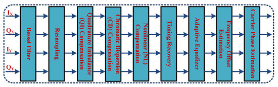
Figure 5.
Algorithm design of the ultra-fast digital signal processors (UDSP).
The imbalances of amplitude and phase within the quadrature (Q) signals and in-phase (I) signals are alleviated by using the compensation of QI. The Gram-Schmidt orthogonalization procedure (GSOP) [18] is used for correcting non-orthogonalization. Two non-orthogonal components from the received signal by and can be defined, the results of the GSOP for a new orthonormal signals can be described by and , as follows:
where is the correlation coefficient; ; and is the ensemble average operator.
Digital filtering can be used for compensating the chromatic dispersion (CD) that is resulting from propagation over fiber. The filter of dispersion compensating can be used in either frequency domain or time domain [19]. The mathematical model of the transfer function for dispersion in the frequency domain can be characterized as follows:
where is the propagation distance, is the wavelength, is the angular-frequency, is the speed of light, is the imaginary-unit, and is the dispersion-coefficient of the optical fiber for the wavelength of , is the dispersion-slope, and is the reference wavelength. A finite impulse response filter (FIR) of the time domain with taps is utilized. The tap weights are described by:
where , is the Nyquist-frequency.
Nonlinear compensation with a digital back propagation (BP) method [20] is performed. Back propagation needs the inverse nonlinear Schrödinger equation (NLSE) [20] to be solved for the optical fiber link. For a single polarization and without spatial domain, the NLSE can be described by:
where is the nonlinear-operator, is the differential operator accounting, and is the complex field, which are given by:
where α is the attenuation coefficient, is the group velocity dispersion factor, and is the nonlinearity factor.
Timing recovery is used for the synchronization of the symbols. The sampling phase and sampling frequency must be determined. The digital square and filter algorithm is utilized [21]. The adaptive equalizer (AE) is used for the compensation of polarization mode dispersion (PMD), the compensation of residual chromatic dispersion and reducing inter-symbol interference. Two-stage Constant modulus algorithm-radius directed (CMA-RD) algorithm is used [22,23]. The received signals are described by:
where are symbols, is the symbol period, is the carrier frequency offset, is the carrier phase, and are zero-mean Gaussian-random-variables. We can then deduce the frequency offset estimate (FOE) which is based on the maximization of the period-gram of as shown below [24]:
The blind phase search (BPS) algorithm [25] is utilized to recover and subsequently to remove the remaining phase mismatch between the signal and the local oscillator. We adopted the BPS algorithm for the carrier phase estimation (CPE).
4. Simulations and Performance Analysis
The transmission system is simulated by OPTISYSTEM and MATLAB. The transmission rate is configured as 900 Gbps; the transmitted sequence-length is configured as 262,144 bit; the number of samples per bit is configured as 4; the Guard-bits is configured as 10; the OSNR is configured above 30 dB; the transmitted optical signal power is configured as 0 dBm.
The interference problems of the adjacent channels can be tested through eight channels in the DWDM system. The interfered degree of adjacent channels in the DWDM system with eight channels is almost the same as that in the DWDM system with more than eight channels. This is because the interference problems of the channels are caused by the bandwidth of the adjacent channels. In our proposed system, the wavelength spacing of adjacent channels is 0.7 nm; the wavelength spacing of non-adjacent channels is more than two times of 0.7 nm, that is to say, the wavelength spacing of non-adjacent channels is more than 1.4 nm. There will be almost no correlation between one channel and the other channels when the signal of each channel is filtered via the GOF, that is, the non-adjacent channels don’t interfere with each other. From the configuration of parameters, we see that the optical spectral utilization efficiency of the transmission channels is up to 10.29 bps/Hz, and it can be calculated by:
The DWDM transmission system with eight channels is simulated and analyzed. The spectrogram output from DWDM-Mux, the spectrogram output from EDFA 1, the spectrogram output from GOF-0 and the constellation diagram output from UDSP are shown in Figure 6a–d, respectively. In Figure 2, the ultra-high-speed photonic-carriers with the adjacent channel spacing of 0.7 nm are multiplexed via DWDM-Mux; the multiplexed signals are amplified via EDFA 1; the amplified signals are transmitted via SSMF; and the signals are amplified by EDFA 2, de-multiplexed by DWDM-Demux, and filtered by GOF-0 successively.
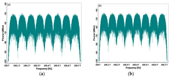
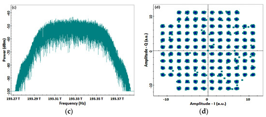
Figure 6.
Spectrograms and constellation diagram. (a) Spectrogram for DWDM, (b) Amplified Spectrogram for DWDM; (c) Spectrogram for one channel signal; (d) Constellation.
The spectrograms output from the other GOFs are similar to Figure 6c, and the locations of the center frequencies are different. The constellation diagram of the coherent receiver unit is shown in Figure 6d. From Figure 6d, it can be seen that the constellations are arranged orderly and clearly.
The order of the GOF is 3; the bandwidth of the GOF is 70 GHz; and the insertion loss of the GOF is 1 mw. The mathematical model of the GOF can then be further described by:
when the bit rate of the transmission system is configured as 900 Gbps, the constellation diagrams and the diagram of the curve between the bandwidth of the GOF and bit error rate (BER) are shown in Figure 7. The constellation diagrams and the diagram of curve between the bandwidth of the GOF and error vector magnitude (EVM) are shown in Figure 8.
Figure 7.
Constellation-diagrams and diagram of curve between the bandwidth of GOF and bit error rate (BER).
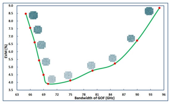
Figure 8.
Constellation-diagrams and diagram of curve between the bandwidth of GOF and error vector magnitude (EVM).
From Figure 7, it can be obtained that the BER of the transmission is greatly influenced by the bandwidth of the GOF. The BER of transmission channel will be worse when the bandwidth of the GOF that is on a wavelength-link diverges from 70 GHz. The BER of transmission channel will be seriously deteriorated when the bandwidth of the GOF that is on a wavelength-link is less than 67 GHz. The constellations output from the UDSP will be arranged orderly and clearly when the bandwidth of the GOF is configured as 70 GHz. However, the constellations output from the UDSP will become blurred when the bandwidth of the GOF diverges from 70 GHz.
From Figure 8, it can be obtained that the EVM output from NTS-128QAM is seriously influenced by the bandwidth of the GOF. The EVM of the transmission channel will be worse when the bandwidth of the GOF that is on a wavelength-link diverges from 70 GHz. The EVM of transmission channel will be deteriorated seriously when the bandwidth of the GOF that is on a wavelength-link is less than 67 GHz. The constellations output from UDSP will be arranged orderly and clearly when the bandwidth of the GOF is configured as 70 GHz. However, the constellations output from the UDSP will become blurred when the bandwidth of the GOF diverges from 70 GHz.
According to Figure 7 and Figure 8, we can learn that BER and EVM are similarly influenced by the bandwidth of the GOF; the degree of influence shows a trend of near synchronization with the change of the bandwidth of the GOF. This also further verifies that there is a certain mathematical function relationship between EVM and BER.
Consequently, the bandwidth of the GOF plays a key role in the overall performances of the transmission system, so it is very important to configure the bandwidth of the GOF properly.
When the transmitted digital symbols of the coherent photonic transmitter are far greater than the number of the constellations (that is, the transmitted digital symbols are far greater than 128), the signal-noise-ratio (SNR) of the transmission system can be expressed as [26]:
where is the energy-spectrum of the noise signal and is the energy per symbol of the useful signal. Then, the relationship between EVM and SNR can be further expressed as:
According to the relationship of the mathematical function between SNR and BER, the following mathematical model can be obtained from [26]:
where is the energy per bit of the useful signal and is the number of binary digits. For example, the sequence-number of 128QAM is 128 (that is, M = 128), and is the error function.
According to and Equations (16) and (17) can be further described by:
Substituting , and consequently, Equation (18) can be further expressed as:
Equation (19) can be described by:
where ; , and it is a mathematical function with respect to EVM, where EVM is a variable.
From Equation (20), it can be obtained that there is a mathematical function relationship between BER and EVM in the system, which further demonstrates that the simulation results are reliable from the trend of curve changes in Figure 7 and Figure 8. The transmission speed of the communication system is configured as 900 Gbps and, the bandwidth of the GOF is set as 70 GHz. We can then obtain the relationship diagrams between BER and OSNR, and EVM and OSNR, which are shown in Figure 9 and Figure 10, respectively.
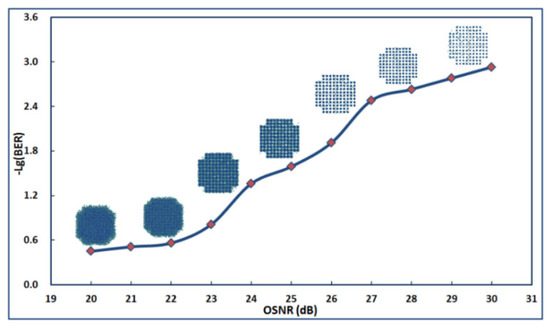
Figure 9.
The relation curve between BER and optical signal-to-noise ratio (OSNR) with constellation-diagrams.
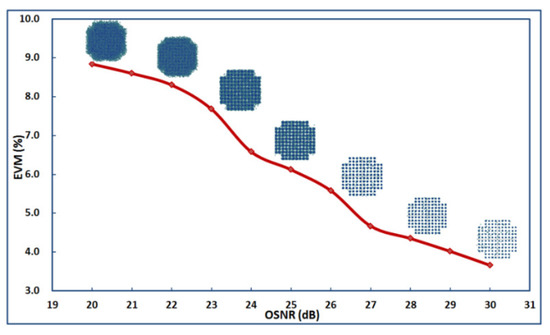
Figure 10.
The relation curve between OSNR and EVM with constellation-diagrams.
From Figure 9, it can be obtained that OSNR has a large impact on BER, and BER decreases rapidly with the increase of OSNR, where BER will reach the optimum value when the value of OSNR is greater than 26 dB. From Figure 10, it can be obtained that the value of EVM shows a large downward trend with the increase of OSNR, where EVM will reach the optimum value when the value of OSNR is greater than 24 dB.
According to Figure 9 and Figure 10, it can be seen that BER and EVM are similarly influenced by OSNR; the degree of influence shows a trend of near synchronization with the change of OSNR. This also further verifies that there is a certain mathematical function relationship between EVM and BER, and also further explains the correctness of Equation (20). Consequently, we can improve OSNR to ameliorate the transmission performance of the communication system.
Furthermore, when the parameters of transmission rates in the single channel are configured as 900 Gbps, 901 Gbps, 902 Gbps, 903 Gbps, 904 Gbps, and 905 Gbps, we can then obtain the constellation-diagrams and diagram of curves between the bit rates and BER, and the bit rates and EVM, which are shown in Figure 11 and Figure 12, respectively.
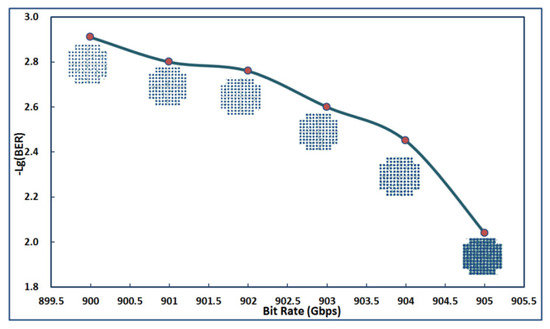
Figure 11.
The relation curve between BER and transmission rates with constellation-diagrams.
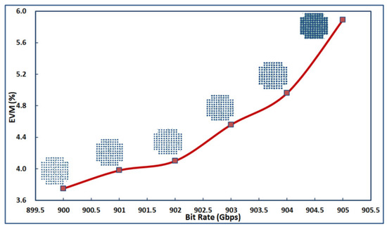
Figure 12.
The relation curve between EVM and transmission rates with constellation-diagrams.
BER is a very important index to measure the performance of a transmission system. According to the conventions of the communication industry, the BER can be acceptable when it falls below the forward error correction threshold of 3.8 × 10⁻³ (that is too say, −lg (BER) ≥ 2.42) for a high-speed digital coherent optical communication system. From Figure 11, it can be seen that when the transmission rate of a single wavelength for the DWDM system configures 904 Gbps, the BER is about 3.8 × 10⁻³; that is too say, when it is configured as N × 904 Gbps for the DWDM system, the transmission performance can be acceptable; meanwhile, the constellation-diagrams are very clear, that is too say, at the receiving terminal, the signals recover well and the distortion is not obvious. Consequently, from N × 900 Gbps to N × 904 Gbps, the transmission rate configuration for the DWDM system is reasonable, and it is also a good choice.
EVM is an index to measure the quality of modulated signal. It indicates the proximity between I/Q components and the ideal components when the receiver demodulates the signals; and the quality of EVM is related to the quality of the signal. In a high-speed digital optical communication, the EVM can be acceptable when it falls below 5%; and this indicator is commonly used in high speed coherent optical communication systems. From Figure 12, it can be obtained that when the bit rate of a single wavelength for the DWDM system is 904 Gbps, the EVM is about 5%; that is too say, when it is configured as N × 904 Gbps for the DWDM system, the transmission performance can be acceptable; Moreover, the constellation-diagrams are very clear, that is too say, at the receiving terminal, the signals recover well and the distortion is not obvious. Consequently, from N × 900 Gbps to N × 904 Gbps, the transmission rate configuration for the DWDM system is reasonable, and it is also a good choice.
From Figure 11 and Figure 12, it can be seen that BER has a specific relationship with EVM in terms of the acceptability of transmission performance corresponding to the rate configuration. This further verifies the rationality of equation (20).
From the configurations and results of the simulations, we calculate that the optical spectral utilization efficiency of the transmission channels is up to 10.33 bps/Hz (904 Gbps/87.5 GHz ≈ 10.33 bps/Hz).
According to all simulations and demonstrations, we determine that the performances of the transmission system are acceptable when the bit rates of the transmission are configured from 900 Gbps to 904 Gbps.
5. Conclusions
We simulated and demonstrated a pulse shaping-based optical transmission of 128QAM for DWDM system with N × 904 Gbps. Gaussian optical filtering is used to produce a photonic carrier. The spectrogram and constellations were obtained by the professional optical communication simulation software. The performances of the transmission system influenced by OSNR and the bandwidth of GOF were analyzed. The relationships between the bandwidth of GOF and BER, OSNR and BER, the bandwidth of GOF and EVM, OSNR and EVM, bit rate and BER, and bit rate and EVM were shown via the curve diagrams. By analytical calculation, theoretical verification, and the comprehensive algorithm compensation, the ultra-speed DWDM transmission system with the wavelength spacing of 87.5 GHz and the single-channel bit rate of 904 Gbps was realized. Meanwhile, the multi-carrier photonic signals were efficiently transmitted over 80 km in a standard single-mode fiber with the optical spectral efficiency of 10.33 bps/Hz.
In the future study, we will further optimize the configuration of parameters to improve the transmission rate, and to decrease BER and EVM. We will also try to utilize the methods of optical Nyquist-samples to ameliorate the optical spectral efficiency, and then improve the entire performance of the transmission system.
Author Contributions
G.L. wrote the manuscript. J.L. reviewed the paper prior to submission. G.L. provided the concept and simulation design of the study. J.L. partially revised the paper. All authors discussed the results, analyzed the data and commented on the manuscript.
Funding
This work is supported by the Science and Technology Plan of Guangzhou in 2017 (Grant No. 201707010173) and the Scientific Research Fund of Guangdong Polytechnic of Science and Technology in 2018 (Grant No. XJPY2018002).
Conflicts of Interest
The authors declare no conflict of interest.
References
- Naohiro, K.; Toshiaki, T.; Norio, C.; Hideo, A. A 25.78-Gbit/s × 4-ch Active Optical Cable with Ultra-compact Form Factor for High-density Optical Interconnects. Appl. Sci. 2018, 8, 137. [Google Scholar]
- Khanna, G.; Rahman, T.; De Man, E.; Riccardi, E.; Pagano, A.; Piat, A.C.; Calabro, S.; Spinnler, B.; Rafique, D.; Feiste, U.; et al. Single-Carrier 400G 64QAM and 128QAM DWDM Field Trial Transmission over Metro Legacy Links. IEEE Photonic Technol. Lett. 2017, 29, 189–192. [Google Scholar] [CrossRef]
- Khanna, G.; Spinnler, B.; Calabrò, S.; Man, E.D.; Feiste, U.; Drenski, T.; Hanik, N. 400G Single Carrier Transmission in 50 GHz Grid Enabled by Adaptive Digital Pre-Distortion. In Proceedings of the 2016 Optical Society of America Optical Fiber Communication Conference, Anaheim, CA, USA, 20–24 March 2016; p. Th3A.3. [Google Scholar] [CrossRef]
- Vincenzo, E.; Marco, L.; Francesco, G.L.; Paola, I. Dimensioning Models of Optical WDM Rings in Xhaul Access Architectures for the Transport of Ethernet/CPRI Traffic. Appl. Sci. 2018, 8, 614. [Google Scholar]
- Rahman, T.; Rafique, D.; Spinnler, B.; Calabro, S.; Man, E.; Feiste, U.; Napoli, A.; Bohn, M.; Khanna, G.; Hanik, N.; et al. Long-Haul Transmission of PM-16QAM-, PM-32QAM-, and PM-64QAM-Based Terabit Super channels Over a Field Deployed Legacy Fiber. J. Lightwave Technol. 2016, 34, 3071–3079. [Google Scholar] [CrossRef]
- Amado, S.B.; Guiomar, F.P.; Muga, N.J.; Reis, J.D.; Pinto, A.N. Experimental Demonstration of the Parallel Split-Step Method in Ultra-Long-Haul 400G Transmission. In Proceedings of the 2015 IEEE European Conference on Optical Communication, Valencia, Spain, 27 September–1 October 2015; p. Th.2.6.2. [Google Scholar] [CrossRef]
- Stanisław, K.; Mateusz, Ż.; Sławomir, S. Optimization of Optical Networks Based on CDC-ROADM Technology. Appl. Sci. 2019, 9, 399. [Google Scholar]
- Buchali, F.; Schuh, K.; Schmalen, L.; Idler, W.; Lach, E.; Leven, A. 1-Tbit/s Dual-carrier DP 64QAM Transmission at 64Gbaud with 40% Overhead Soft-FEC over 320 km SSMF. In Proceedings of the 2013 IEEE Optical Fiber Communication Conference, Anaheim, CA, USA, 17–21 March 2013; p. OTh4E.3. [Google Scholar] [CrossRef]
- Buchali, F.; Idler, W.; Schuh, K.; Brast, T.; Schmid, S.; Steffan, A.; Cameron, N. 1 Tb/s-4x343 Gb/s Subcarriers on 50GHz Grid- Transmission over 480 km SMF with 22 GHz Bandwidth Semiconductor Modulator. In Proceedings of the 2014 IEEE Optical Fiber Communications Conference & Exhibition, San Francisco, CA, USA, 9–13 March 2014; p. Th4F.2. [Google Scholar] [CrossRef]
- Cao, J.T.; Yang, Y.F.; Xiang, Q.; Zhang, Q.; Fan, L.S.; Yao, Y. A Pilot Symbols Aided Adaptive Kalman Filter for Joint Carrier Phase and Polarization Tracking in Coherent Optical System. Appl. Sci. 2019, 9, 27. [Google Scholar] [CrossRef]
- Zhang, D.; Hao, S.; Zhao, Q.; Zhao, Q.; Wang, L.; Wan, X. Wavefront Reconstruction Method Based on Wavelet Fractal Interpolation for Coherent Free Space Optical Communication. Opt. Commun. 2018, 410, 723–729. [Google Scholar] [CrossRef]
- Li, G.; Li, J.Q.; Chen, G.J.; Huang, X.G. SOA-based AOWC of 128QAM Using Gaussian Pulse Shaping for Transmission System with 227 Gbps. Microw. Opt. Technol. Lett. 2018, 60, 2204–2216. [Google Scholar] [CrossRef]
- Zong, K.; Zhu, J. Performance Evaluation and Optimization of Multiband Phase-modulated Radio over IsOWC Link with Balanced Coherent Homodyne Detection. Opt. Commun. 2018, 413, 152–156. [Google Scholar] [CrossRef]
- Zhong, K.P.; Zhou, X.; Huo, J.; Yu, C.Y.; Lu, C.; Alan, P.T.L. Digital Signal Processing for Short-reach Optical Communications: A Review of Current Technologies and Future Trends. J. Lightwave Technol. 2018, 36, 377–400. [Google Scholar] [CrossRef]
- Li, H.W.; Huang, Y.M.; Wang, Q.; He, D.; Peng, Z.M.; Li, Q. Performance Analysis of Satellite-to-Ground Coherent Optical Communication System with Aperture Averaging. Appl. Sci. 2018, 8, 2496. [Google Scholar] [CrossRef]
- Cartledge, J.C.; Rolland, C.; Lemerle, S.; Solheim, A. Theoretical Performance of 10 Gbps Lightwave Systems Using a III-vsemiconductor Mach-zehnder Modulator. IEEE Photonic Technol. Lett. 1994, 6, 282–284. [Google Scholar] [CrossRef]
- Cartledge, J.C. Performance of 10 Gbps Lightwave Systems Based on Lithium Niobate Mach-Zehnder Modulators with Asymmetric Y-branch Waveguides. IEEE Photonic Technol. Lett. 1995, 7, 1090–1092. [Google Scholar] [CrossRef]
- Fatadin, I.; Savory, S.J.; Ives, D. Compensation of Quadrature Imbalance in an Optical QPSK Coherent Receiver. IEEE Photonic Technol. Lett. 2008, 20, 1733–1735. [Google Scholar] [CrossRef]
- Savory, S.J. Digital Filters for Coherent Optical Receivers. Opt. Express 2008, 16, 804–817. [Google Scholar] [CrossRef] [PubMed]
- Du, L.B.; Lowery, A.J. Improved Single Channel Back Propagation for Intra-channel Fiber Nonlinearity Compensation in Long-haul Optical Communication Systems. Opt. Express 2010, 18, 17075–17088. [Google Scholar] [CrossRef] [PubMed]
- Oerder, M.; Meyr, H. Digital Filter and Square Timing Recovery. IEEE Trans. Commun. 1988, 36, 605–612. [Google Scholar] [CrossRef]
- Godard, D.N. Self-Recovering Equalization and Carrier Tracking in Two-Dimensional Data Communication Systems. IEEE Trans. Commun. 1980, 28, 1867–1875. [Google Scholar] [CrossRef]
- Sethares, W.A.; Rey, G.A.; Johnson, C.R. Approaches to Blind Equalization of Signals with Multiple Modulus. In Proceedings of the 1989 IEEE International Conference on Acoustics, Signal Processing, Glasgow, UK, 23–26 May 1989; pp. 972–975. [Google Scholar]
- Morelli, M.; Mengali, U. Feedforward Frequency Estimation for PSK: A Tutorial Review. Eur. Trans. Telecommun. 1998, 9, 103–116. [Google Scholar] [CrossRef]
- Pfau, T.; Hoffmann, S.; Noe, R. Hardware-efficient Coherent Digital Receiver Concept with Feedforward Carrier Recovery for M-QAM Constellations. J. Lightwave Technol. 2009, 27, 989–999. [Google Scholar] [CrossRef]
- Webb, W.T.; Hanzo, L.; Steele, R. Bandwidth-efficient QAM Schemes for Rayleigh Fading Channels. In Proceedings of the IET International Conference on Radio Receivers and Associated Systems, Cambridge, UK, 23–27 July 1990. [Google Scholar]
© 2019 by the authors. Licensee MDPI, Basel, Switzerland. This article is an open access article distributed under the terms and conditions of the Creative Commons Attribution (CC BY) license (http://creativecommons.org/licenses/by/4.0/).