MM-Wave Phased Array Quasi-Yagi Antenna for the Upcoming 5G Cellular Communications

 ,
,  ,
,  ,
,  ,
, 
Abstract
:
1. Introduction
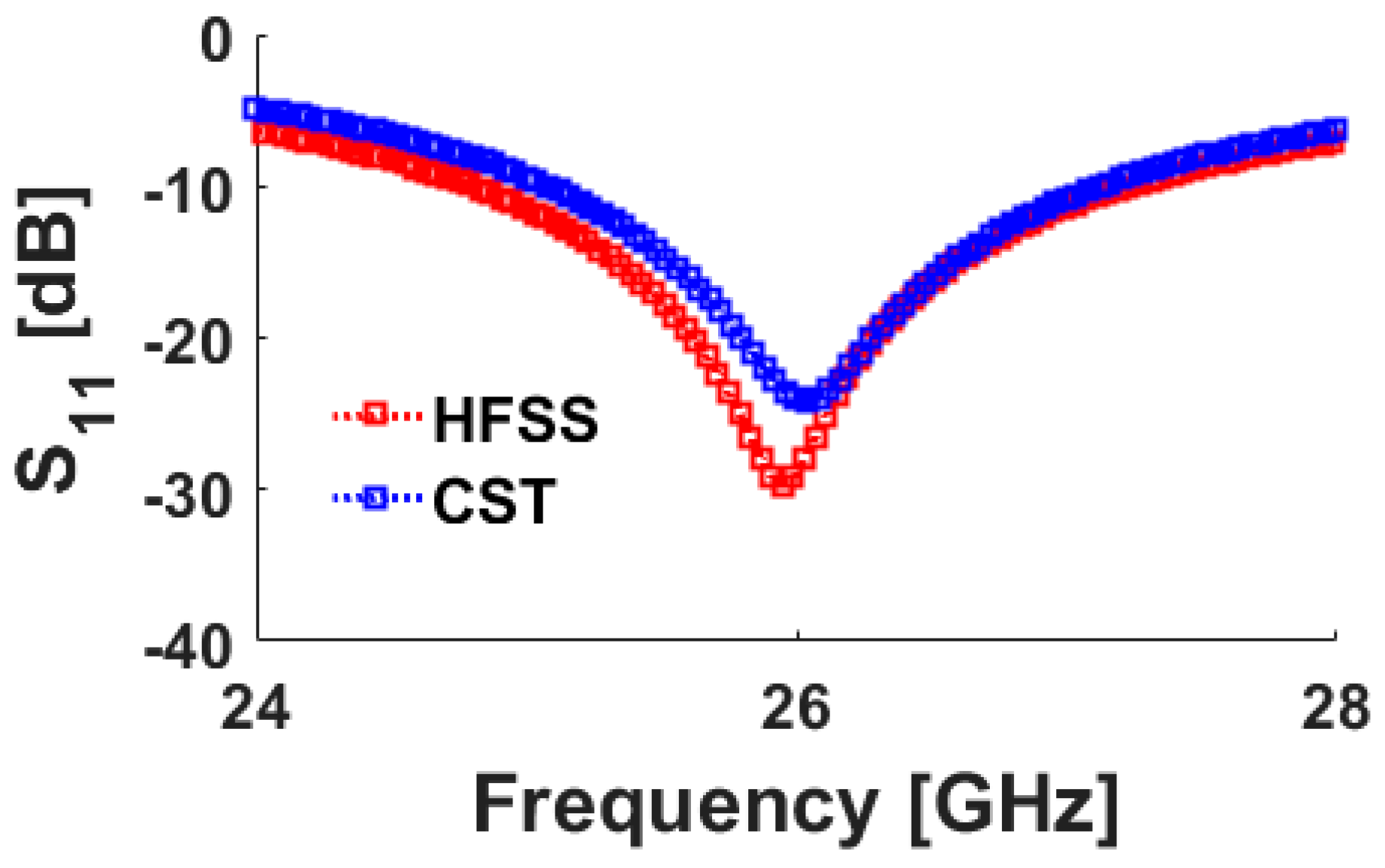
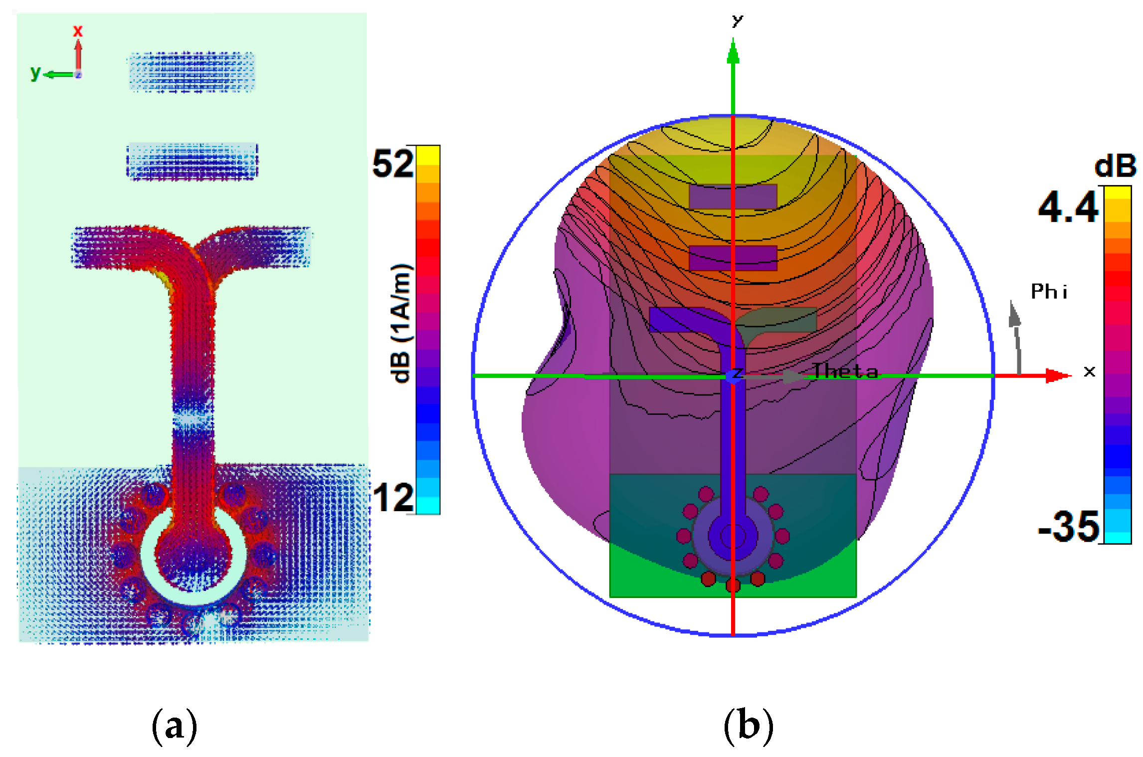
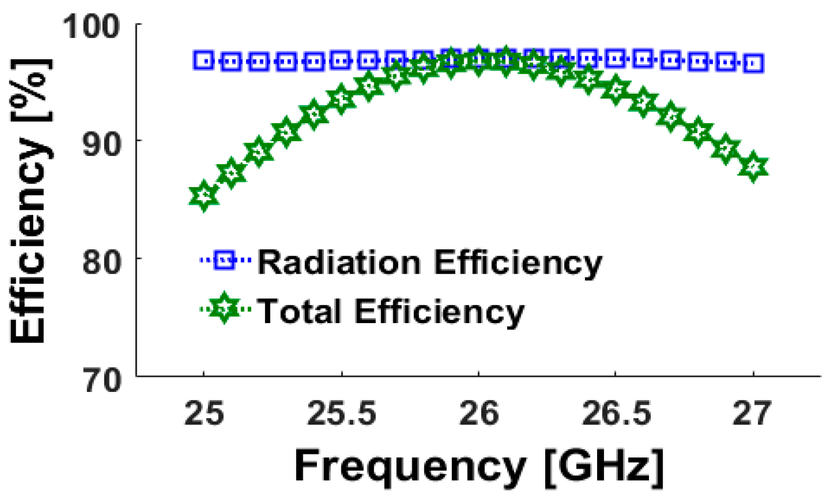
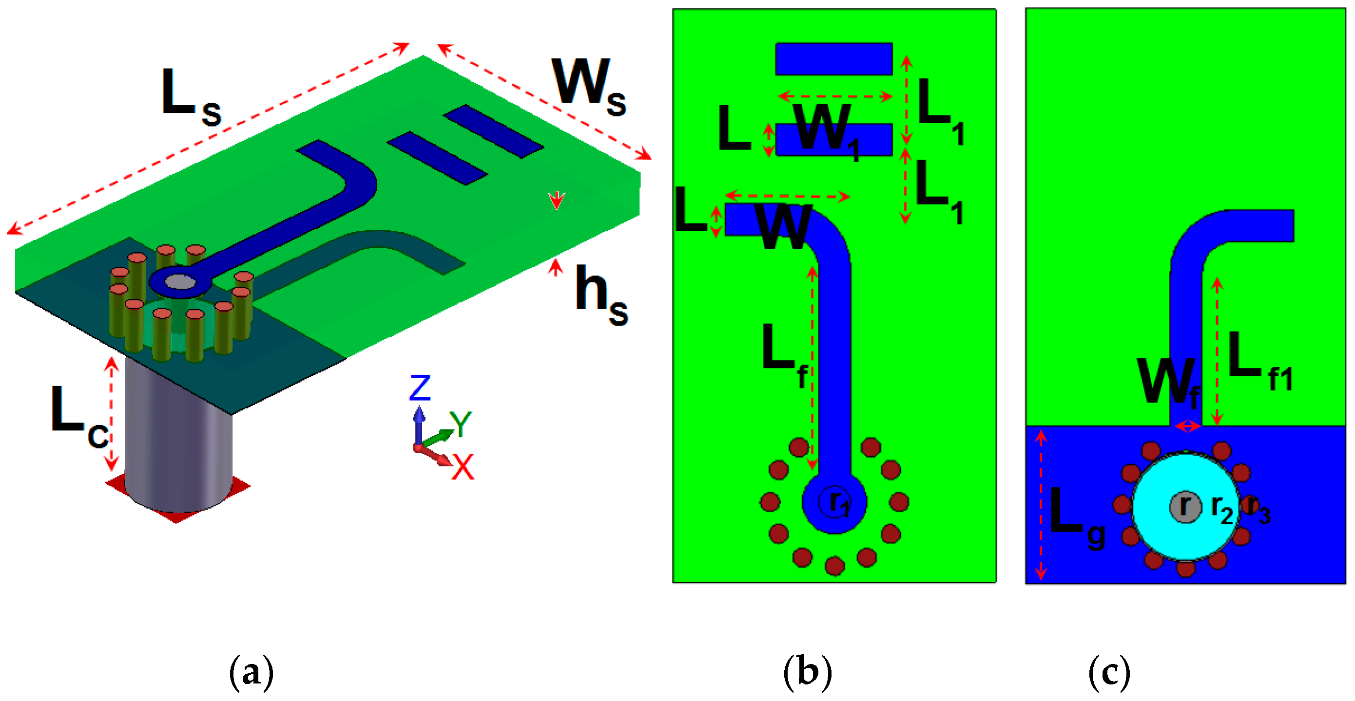
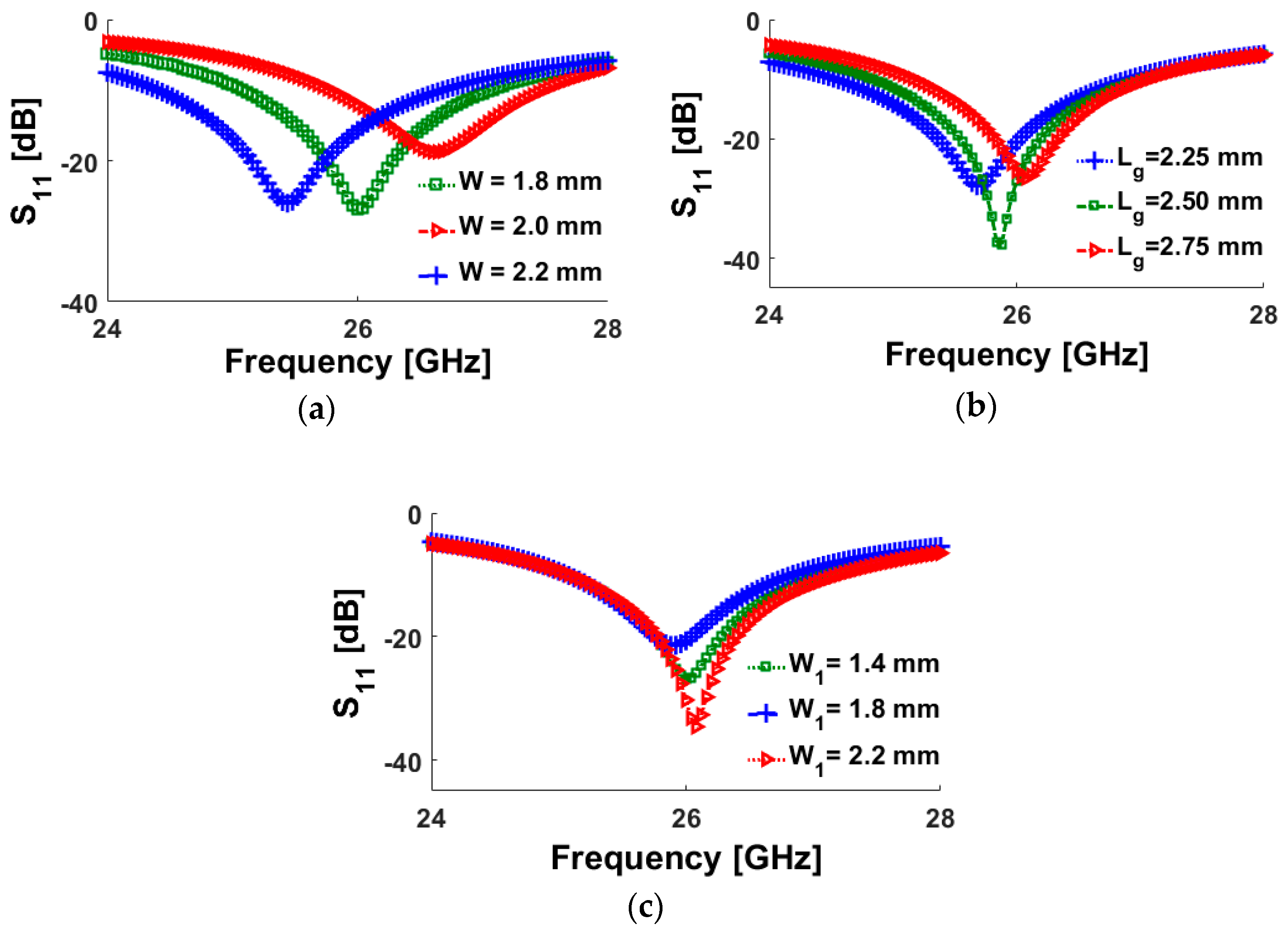
2. Quasi-Yagi Antenna
3. The Phased Array 5G Smartphone Antenna
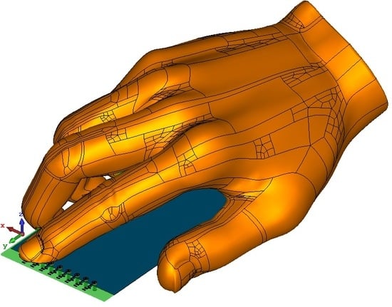
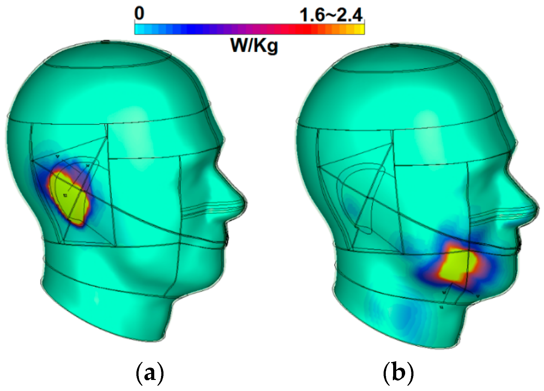
4. User-Impact on the Proposed Smartphone Antenna
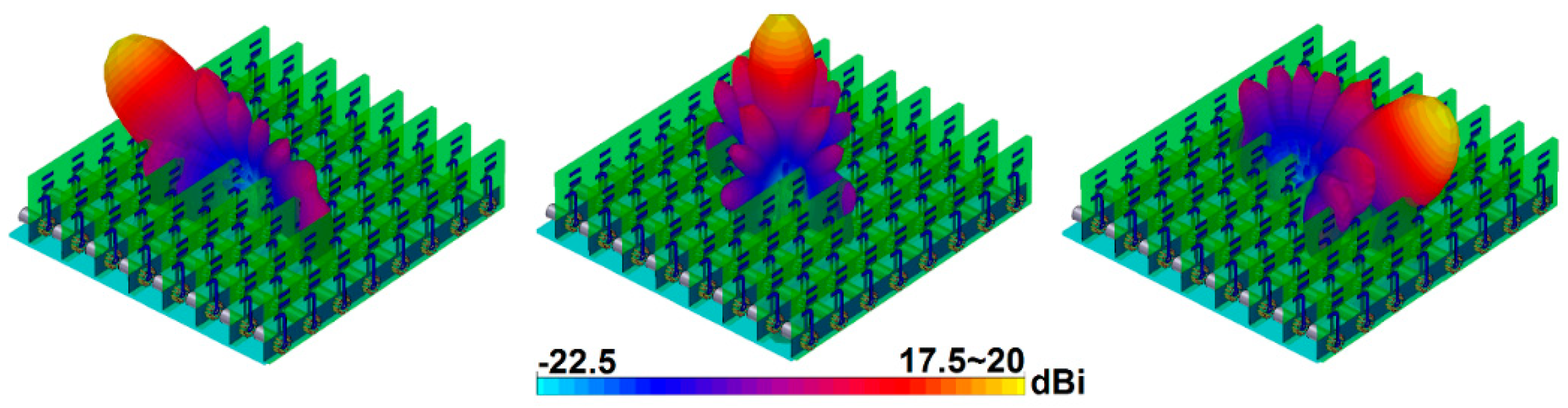
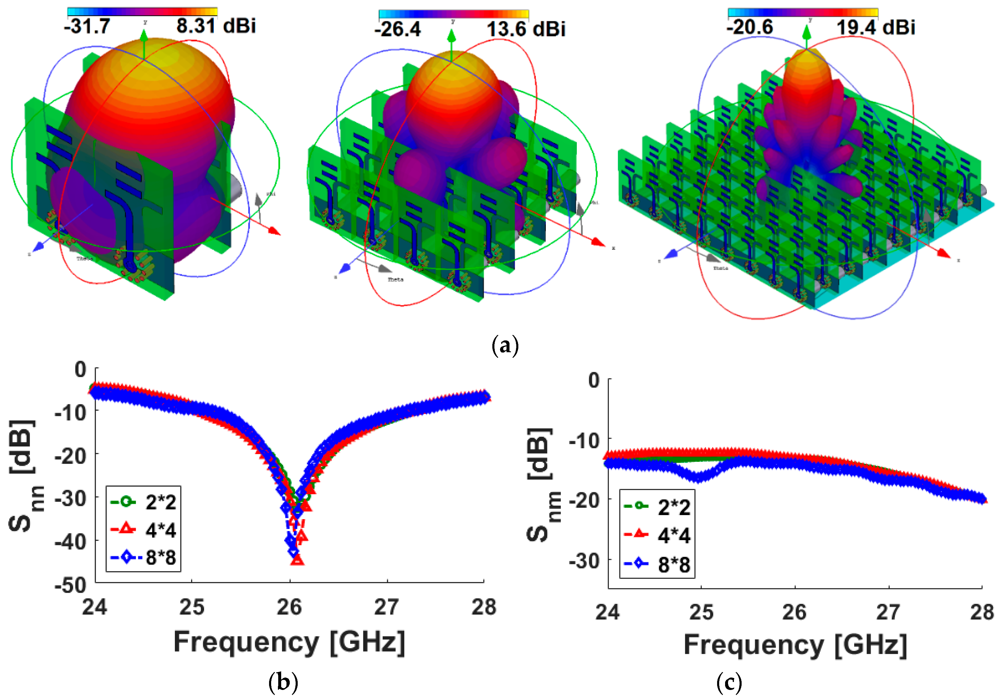
5. Planar Phased Array Design of the 26 GHz Quasi-Yagi Antenna
6. Conclusions
Author Contributions
Funding
Acknowledgments
Conflicts of Interest
References
- Rappaport, T.S.; Sun, S.; Mayzus, R.; Zhao, H.; Azar, Y.; Wang, K.; Wong, G.N.; Schulz, J.K.; Samimi, M.; Gutierrez, F. Millimeter wave mobile communications for 5G cellular: It will work! IEEE Access 2013, 1, 335–349. [Google Scholar] [CrossRef]
- Osseiran, A.; Boccardi, F.; Braun, V.; Kusume, K.; Marsch, P.; Maternia, M.; Queseth, O.; Schellmann, M.; Schotten, H.; Taoka, H.; et al. Scenarios for 5G mobile and wireless communications: The vision of the METIS project. IEEE Commun. Mag. 2014, 52, 26–35. [Google Scholar] [CrossRef]
- Roh, W.; Seol, J.; Park, J.; Lee, B.; Lee, J.; Kim, Y.; Cho, J.; Cheun, K.; Aryanfar, F. Millimeter-wave beamforming as an enabling technology for 5G cellular communications: Theoretical feasibility and prototype results. IEEE Commun. Mag. 2014, 52, 106–113. [Google Scholar] [CrossRef]
- Ofcom. Available online: https://www.ofcom.org.uk/ (accessed on 8 February 2017).
- Bai, T.; Heath, R. Coverage and rate analysis for millimeter wave cellular networks. IEEE Trans. Wirel. Commun. 2015, 14, 1110–1114. [Google Scholar] [CrossRef]
- Jilani, S.F.; Munoz, M.O.; Abbasi, Q.H.; Alomainy, A. Millimeter-wave liquid crystal polymer based conformal antenna array for 5G applications. IEEE Antennas Wirel. Propag. Lett. 2019, 18, 84–88. [Google Scholar] [CrossRef]
- Ojaroudiparchin, N.; Shen, M.; Zhang, S.; Pedersen, G.F. A switchable 3-D-coverage-phased array antenna package for 5G mobile terminals. IEEE Antennas Wirel. Propag. Lett. 2016, 15, 1747–1750. [Google Scholar] [CrossRef]
- Zhang, J.; Zhang, S.; Lin, X.; Fan, Y.; Pedersen, G. 3D radiation pattern reconfigurable phased array for transmission angle sensing in 5G mobile communication. Sensors 2018, 18, 4204. [Google Scholar] [CrossRef] [PubMed]
- Ojaroudiparchin, N.; Shen, M.; Pedersen, G.F. Multi-layer 5G mobile phone antenna for multi-user MIMO communications. In Proceedings of the 2015 23rd Telecommunications Forum Telfor (TELFOR), Belgrade, Serbia, 24–26 November 2015. [Google Scholar]
- Ojaroudiparchin, N.; Shen, M.; Pedersen, G.F. Beam-steerable microstrip-fed bow-tie antenna array for fifth generation cellular communications. In Proceedings of the 2016 10th European Conference on Antennas and Propagation (EuCAP), Davos, Switzerland, 10–15 April 2016. [Google Scholar]
- Parchin, N.O.; Shen, M.; Pedersen, G.F. Small-size tapered slot antenna (TSA) design for use in 5G phased array applications. Appl. Comput. Electromagn. Soc. (ACES) J. 2017, 3, 1054–4887. [Google Scholar]
- Xu, Q.; Biedka, M.; Wang, Y.E. Indented antenna arrays for high isolation: The growing interest in simultaneous-transmit-and-receive-based full-duplex communication systems. IEEE Antennas Propag. Mag. 2018, 60, 72–80. [Google Scholar] [CrossRef]
- Morgan, M.; Weinreb, S. A millimeter-wave perpendicular coax-to-microstrip transition. In Proceedings of the 2002 IEEE MTT-S International Microwave Symposium Digest (Cat. No. 02CH37278), Seattle, WA, USA, 2–7 June 2002. [Google Scholar]
- Zhao, A.; Ai, F. 5G mm-wave antenna array based on T-slot antenna for mobile terminals. In Proceedings of the 2018 IEEE Asia-Pacific Conference on Antennas and Propagation (APCAP), Auckland, New Zealand, 5–8 August 2018. [Google Scholar]
- Ojaroudiparchin, N.; Shen, M.; Pedersen, G.F. A 28 GHz FR-4 compatible phased array antenna for 5G mobile phone applications. In Proceedings of the International Symposium on Antennas and Propagation (ISAP 2015), Tasmania, Australia, 9–12 November 2015. [Google Scholar]
- Ojaroudi Parchin, N.; Al-Yasir, Y.; Abdulkhaleq, A.M.; Elfergani, I.; Rayit, A.; Noras, J.M.; Rodriguez, J.; Abd-Alhameed, R.A. Frequency reconfigurable antenna array for mm-Wave 5G mobile handsets. In Proceedings of the 9th International Conference on Broadband Communications, Networks, and Systems, Faro, Portugal, 19–20 September 2018. [Google Scholar]
- Tatomirescu, A.; Oprian, A.; Zhekov, S.; Pedersen, G.F. Beam-steering array for handheld devices targeting 5G. In Proceedings of the 2015 International Symposium on Antennas and Propagation (ISAP), Hobart, TAS, Australia, 9–12 November 2015. [Google Scholar]
- CST Microwave Studio; ver. 2017; CST: Framingham, MA, USA, 2017.
- Kaneda, N.; Deal, W.R.; Qian, Y.; Waterhouse, R.; Itoh, T. A broadband planar quasi-Yagi antenna. IEEE Trans. Antennas Propag. 2002, 50, 1158–1160. [Google Scholar] [CrossRef]
- Ansoft High Frequency Structure Simulation (HFSS); Ver. 17; Ansoft Corporation: Pittsburgh, PA, USA, 2017.
- Ojaroudiparchin, N.; Shen, M.; Pedersen, G.F. Investigation on the performance of low-profile insensitive antenna with improved radiation characteristics for the future 5G applications. Microw. Opt. Technol. Lett. 2016, 58, 2148–2158. [Google Scholar] [CrossRef]
- Jamesn, J.R.; Hall, P.S. Handbook of Microstrip Antennas; Peter Peregrinus Ltd.: London, UK, 1989. [Google Scholar]
- Amitay, N.; Galindo, V.; Wu, C.P. Theory and Analysis of Phased Array Antennas; Wiley Interscience: Hoboken, NJ, USA, 1972. [Google Scholar]
- Hong, W.; Ko, S.T.; Lee, Y.; Baek, K.H. Multi-polarized antenna array configuration for mm-Wave 5G mobile terminals. In Proceedings of the 2015 International Workshop on Antenna Technology (iWAT), Seoul, Korea, 4–6 March 2015. [Google Scholar]
- Ojaroudiparchin, N.; Shen, M.; Pedersen, G.F. 8 × 8 planar phased array antenna with high efficiency and insensitivity properties for 5G mobile base stations. In Proceedings of the 2016 10th European Conference on Antennas and Propagation (EuCAP), Davos, Switzerland, 10–15 April 2016. [Google Scholar]
- Hansen, R.C. Phased Array Antennas; John Wiley & Sons, Inc.: New York, NY, USA, 2009. [Google Scholar]
- Parchin, N.O. Low-profile air-filled antenna for next generation wireless systems. Wirel. Pers. Commun. 2017, 97, 3293–3300. [Google Scholar] [CrossRef]
- Khan, R.; Al-Hadi, A.A.; Soh, P.J. Recent advancements in user effect mitigation for mobile terminal antennas: A review. IEEE Trans. Electromagn. Compat. 2019, 16, 279–287. [Google Scholar] [CrossRef]
- Bonev, I.B.; Franek, O.; Pedersen, G.F. Impact of the hand on the specific absorption rate in the head. Appl. Comput. Electromagn. Soc. (ACES) J. 2014, 29, 470–477. [Google Scholar]
- Ojaroudiparchin, N.; Shen, M.; Pedersen, G.F. Design of Vivaldi antenna array with end-fire beam steering function for 5G mobile terminals. In Proceedings of the 2015 23rd Telecommunications Forum Telfor (TELFOR), Belgrade, Serbia, 24–26 November 2015. [Google Scholar]
- Moustafa, J.; McEwan, N.J.; Abd-Alhameed, R.A.; Excell, P.S. Low SAR phased antenna array for mobile handsets. Appl. Comput. Electromagn. Soc. (ACES) J. 2006, 21, 196–205. [Google Scholar]
- Faruque, M.R.I. Evaluation of EM absorption in human head with metamaterial attachment. Appl. Comput. Electromagn. Soc. (ACES) J. 2010, 25, 1097–1107. [Google Scholar]
- Ojaroudiparchin, N.; Shen, M.; Pedersen, G.F. Low-cost planar mm-Wave phased array antenna for use in mobile satellite (MSAT) platforms. In Proceedings of the 23rd Telecommunications forum (TELFOR), Belgrade, Serbia, 24–26 November 2015; pp. 587–590. [Google Scholar]
- Ojaroudi Parchin, N.; Abd-Alhameed, R.A. A compact Vivaldi antenna array for 5G channel sounding applications. In Proceedings of the 12th European Conference on Antennas and Propagation (EuCAP 2018), London, UK, 9–13 April 2018. [Google Scholar]


| Parameter | Value (mm) | Parameter | Value (mm) | Parameter | Value (mm) |
|---|---|---|---|---|---|
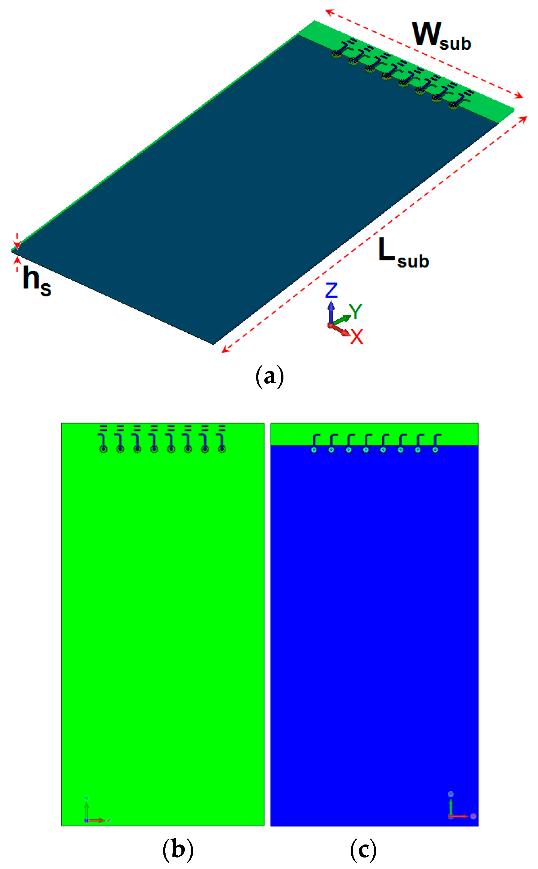
| Wsub | 60 | Lsub | 120 | hS | 0.8 |
| WS | 4.5 | Lg | 2.5 | Wf | 0.5 |
| Lf | 3.15 | LC | 3 | W | 1.95 |
| L | 0.1 | Wa | 40 | LS = La | 9 |
| W1 | 1.8 | L1 | 1.25 | r1 | 0.5 |
| r2 | 0.87 | r3 | 0.15 | R | 0.25 |
| Reference | Bandwidth (GHz) | Efficiency (%) | Gain (dB) | Element Size (mm2) | Isolation (dB) | Scanning Range |
|---|---|---|---|---|---|---|
| [7] | 21–22 | - | 8–12 | - | 14 | 0°~75° |
| [8] | 27.5–28.5 | 70 | 7–11 | 7 × 5.5 | 11 | 0°~60° |
| [9] | 27–29 | 80 | 8–11 | 5.5 × 5.5 | 14 | 0°~60° |
| [10] | 16–18 | - | 7–11.5 | 9 × 9 | 17 | 0°~60° |
| [11] | 21–23 | 85 | 9–12 | 12 × 6 | 12 | 0°~75° |
| [14] | 27.4–28.8 | - | 7–11 | 9 × 6 | 16 | 0°~60° |
| [16] | 27–29 | 80 | 5–9.5 | 5 × 4 | 13 | 0°~75° |
| [17] | 27.5–28.5 | - | 8–11.5 | - | 15 | 0°~60° |
| Proposed | 25–27 | 90 | 10.5–12 | 9 × 4.5 | 16 | 0°~75° |
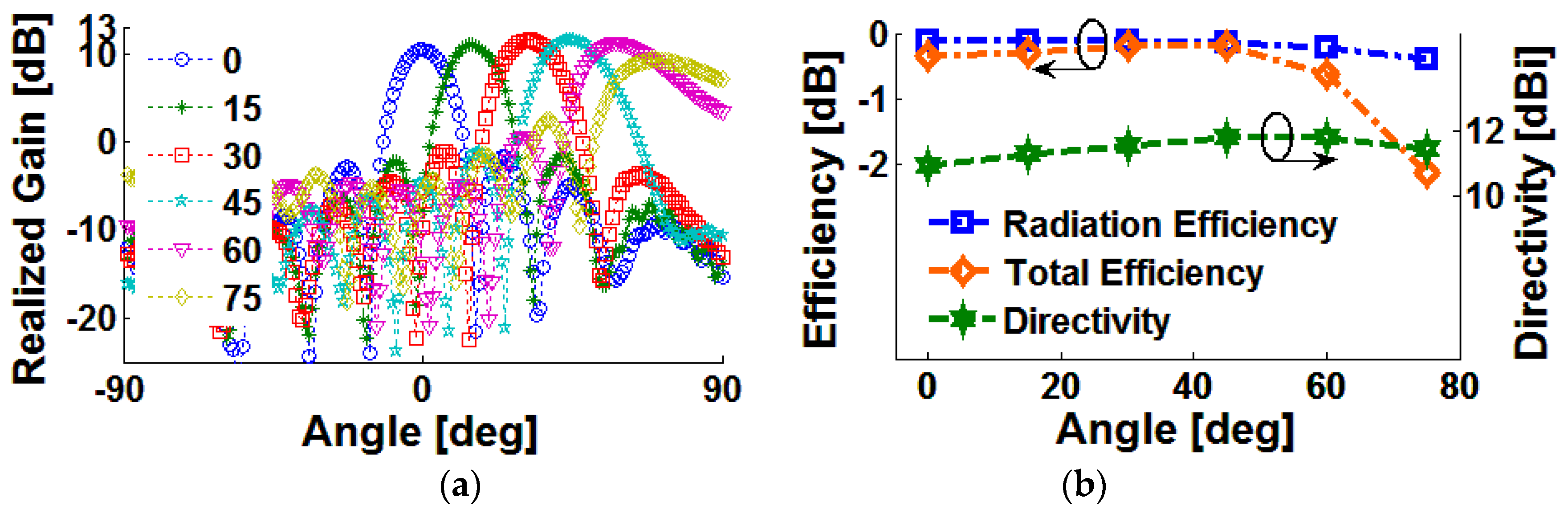
| Param./Angle | 0° | 15° | 30° | 45° | 60° | 75° |
|---|---|---|---|---|---|---|
| Rad. Effic. (dB) | −1.52 | −1.56 | −1.78 | −2.11 | −2.56 | −2.83 |
| Tot. Effic. (dB) | −2.03 | −2.08 | −2.25 | −2.78 | −2.64 | −4.5 |
| Directivity (dBi) | 11.8 | 12.1 | 12 | 11.92 | 11.6 | 10.8 |
| Rlzd. Gain (dB) | 9.8 | 10 | 9.77 | 9.14 | 8.12 | 6.4 |
© 2019 by the authors. Licensee MDPI, Basel, Switzerland. This article is an open access article distributed under the terms and conditions of the Creative Commons Attribution (CC BY) license (http://creativecommons.org/licenses/by/4.0/).
Share and Cite
Ojaroudi Parchin, N.; Alibakhshikenari, M.; Jahanbakhsh Basherlou, H.; A. Abd-Alhameed, R.; Rodriguez, J.; Limiti, E. MM-Wave Phased Array Quasi-Yagi Antenna for the Upcoming 5G Cellular Communications. Appl. Sci. 2019, 9, 978. https://doi.org/10.3390/app9050978
Ojaroudi Parchin N, Alibakhshikenari M, Jahanbakhsh Basherlou H, A. Abd-Alhameed R, Rodriguez J, Limiti E. MM-Wave Phased Array Quasi-Yagi Antenna for the Upcoming 5G Cellular Communications. Applied Sciences. 2019; 9(5):978. https://doi.org/10.3390/app9050978
Chicago/Turabian StyleOjaroudi Parchin, Naser, Mohammad Alibakhshikenari, Haleh Jahanbakhsh Basherlou, Raed A. Abd-Alhameed, Jonathan Rodriguez, and Ernesto Limiti. 2019. "MM-Wave Phased Array Quasi-Yagi Antenna for the Upcoming 5G Cellular Communications" Applied Sciences 9, no. 5: 978. https://doi.org/10.3390/app9050978
APA StyleOjaroudi Parchin, N., Alibakhshikenari, M., Jahanbakhsh Basherlou, H., A. Abd-Alhameed, R., Rodriguez, J., & Limiti, E. (2019). MM-Wave Phased Array Quasi-Yagi Antenna for the Upcoming 5G Cellular Communications. Applied Sciences, 9(5), 978. https://doi.org/10.3390/app9050978