Article

Near-Infrared Quartz-Enhanced Photoacoustic Sensor for H2S Detection in Biogas

1
College of Physics and Electronic Engineering, Shanxi University, Taiyuan 030006, China
2
PolySense Lab, Physics Department, Politecnico di Bari, I-70100 Bari, Italy
3
State Key Laboratory of Quantum Optics and Quantum Optics Devices, Institute of Laser Spectroscopy, Shanxi University, Taiyuan 030006, China
4
Collaborative Innovation Center of Extreme Optics, Shanxi University, Taiyuan 030006, China
*
Authors to whom correspondence should be addressed.
Appl. Sci. 2019, 9(24), 5347; https://doi.org/10.3390/app9245347
Submission received: 10 November 2019 / Revised: 29 November 2019 / Accepted: 4 December 2019 / Published: 6 December 2019
(This article belongs to the Special Issue Quartz-Enhanced Photoacoustic and Photothermal Spectroscopy)

Abstract

:
A quartz-enhanced photoacoustic spectroscopy (QEPAS) sensor for H2S detection operating in near-infrared spectral range is reported. The optical source is an erbium-doped fiber amplified laser with watt-level optical power. The QEPAS spectrophone is composed of a quartz tuning fork with a resonance frequency of 7.2 kHz, a quality factor of 8500, and a distance between prongs of 800 µm, and two tubes with a radius of 1.3 mm and a length of 23 mm acting as an organ pipe resonator. With this spectrophone geometry, the photothermal noise contribution of the spectrophone was removed and the theoretical thermal noise level was achieved. The position of both tubes with respect to custom quartz tuning fork has been investigated as a function of signal amplitude, Q-factor, and noise of the QEPAS sensor when a high-power laser was used. Benefit from the linearity of the QEPAS signal to the excitation laser power, a detection sensitivity of 330 ppb for H2S detection was achieved at atmospheric pressure and room temperature, when the laser power was 1.6 W and the signal integration time was set to 300 ms, corresponding to a normalized noise equivalent absorption of 3.15 × 10⁻⁹ W cm−1/(Hz)1/2. The QEPAS sensor was then validated by measuring H2S in a biogas sample.

1. Introduction

Hydrogen sulfide (H2S), a colorless, extremely toxic, acidic gas, is an important chemical raw material [1]. The monitoring of H2S is widely spread in iron smelters, landfills, petrochemical companies, and agriculture. H2S can cause serious harm to human health, even in low concentration levels [2,3]. According to the National Institute of Occupational Safety and Health, long-term exposition to concentrations up to 10 part-per-million (ppm) can cause human health damage, and more than 100 ppm H2S can lead to death [4]. Hence, applications of the accurate H2S monitoring require reliable, efficient, and highly sensitive sensing systems.
Currently, methods most commonly used to detect hydrogen sulfide in environmental samples include gas chromatography with electron capture detection [5], iodometric methods [6], the methylene blue colorimetric method [7], and potentiometric titration with a sulfide ion-selective electrode [8]. All these methods suffer from slow time response and short lifespan. In addition, gas chromatography tends to be costly, invasive, and occupy a large spatial footprint, thus cannot be used for real-time and in-situ applications.
Optical gas sensors based on laser absorption spectroscopy (LAS) can represent a suitable solution for in-situ and fast trace gas detection, since they exploit the laser’s narrow spectral resolution, allowing high sensitivity and selectivity [9,10,11,12,13,14,15]. In LAS, the gas concentration information is obtained by detecting the optical intensity via a photodetector. Among all LAS-based techniques, the optical sensors for trace gas detection can be divided in three major groups: (i) Direct absorption-based sensors, in which the laser beam passes through a single- or multi-pass absorption cell [16], (ii) cavity-enhanced based sensors, in which the gas cell is composed of a Fabry–Perot optical resonator [17], (iii) photoacoustic spectroscopy (PAS) sensors, where an acoustic cell is used to amplify sound waves generated by the gas itself when it absorbs intensity-modulated light [18]. Both multi-pass cells and optical cavities must be combined with optical detectors. The main strength of PAS is that no optical detectors are needed, and wavelength-insensitive microphones are used to detect the weak sound waves within the absorbing gas.
Quartz-enhanced photoacoustic spectroscopy (QEPAS) is an excellent alternative to the conventional PAS, which eliminates constraints due to the acoustic cell size because the weak photoacoustic signal is detected via a quartz tuning fork (QTF) instead of a microphone [19,20,21]. A laser beam is focused between QTF prongs and sound waves produced by the modulated absorption of the gas put the QTF prongs in vibration. When the laser modulation frequency is resonant with one of the in-plane anti-symmetrical flexural modes of the QTF, the QTF converts the vibration energy into electrical energy through the piezoelectric effect occurring in the quartz crystal [22,23]. Because of the quartz piezoelectric property, the strain induced by the acoustic wave hitting the QTF prongs generates electrical charges. QTF prongs are provided with golden patterns for collecting the electric charges and generating, in turn, an electrical signal. The electrical signal s will be proportional to the intensity of the sound wave by the relation: s = C·P·cgas·σ, where cgas is the gas concentration, P is the optical power, N the number of the molecule per unit volume and σ the optical transition cross-section [19].
To probe and amplify the sound wave generated between QTF prongs, an acoustic resonator system is usually coupled with the QTF. The acoustic system composed of a QTF and an acoustic resonator is referred to as a QEPAS spectrophone [24]. The acoustic resonators consist of two metallic tubes aligned perpendicularly to the QTF plane (dual-tube spectrophone) and the laser beam is forced to pass through the tubes (on-beam QEPAS configuration). For commercial QTF (resonance frequency f0 ~ 32,768 Hz), the dual-tube spectrophone can improve the QEPAS signal up to a factor of ~30 with respect to the bare QTF [25]. By using custom-made QTFs, this factor has been enhanced up to ~60 [26]. Furthermore, custom QTFs with large prong spacing have extended the QEPAS technique with a laser having poor spatial beam quality, such as LEDs or THz QCLs [27,28]. Large prong spacings, as well as large tube diameters, allowed to significantly reduce the stray light touching the spectrophone, leading to a strong reduction of the photothermal noise contribution [29].
QEPAS technique has been already used for H2S detection. De Cumis et al. [30] reported an H2S QEPAS sensor with a detection limit of 450 ppb with 3 s averaging times by using a single-mode, fiber-coupled, QCL operating at 7.89 μm. Spagnolo et al. [31] reported an H2S QEPAS sensor exploiting a custom QTF with a prong spacing as large as 700 µm and a THz QCL emitting at 2.91 THz. Detection sensitivity of 13 ppm with 30 s integral time has been reached. Such low detection limits have been achieved mainly because the line-strengths of the H2S lines located in the mid- and far-infrared spectral range are two or three orders of magnitude higher than that of the near-infrared H2S lines [32]. Even if the THz QCLs suffer from low power, strong and interferent-free absorption lines can be detected. Conversely, mid-IR QCLs can reach optical powers of few tens of milliwatts that compensate H2S absorption lines weaker than those in the THz range. The near-infrared range is a challenge for H2S detection both because diode lasers’ optical power levels are lower than QCLs and absorption lines are weaker than those falling in the mid-infrared spectral range. As the performance of QEPAS sensors linearly increases with the excitation laser, Wu et al. [33] reached an H2S detection limit of 142 part-per-billion (ppb) by exploiting an erbium-doped fiber amplifier (EDFA) coupled with a near-infrared diode laser, allowing to reach a watt-level excitation laser power. In addition, to get such detection sensitivity, the electrical modulation cancellation method was used to eliminate the high noise resulting from the stray light touching the QTF, which makes the sensor bulky and hard to use [34].
In this work, a fiber-amplifier-enhanced QEPAS sensor for H2S detection employing an erbium-doped fiber amplified distributed-feedback diode laser and dual-tube spectrophone with a custom QTF with a prong spacing of 800 μm is employed. The impact of the resonator tube position with respect to the custom QTF on QEPAS signal and QTF quality factor Q was investigated at different laser powers. The sensor was calibrated starting from a 50 ppm H2S:N2 certified gas mixture.

2. Description of Experimental System

The main requirement for a QEPAS sensor is to avoid spectral interference effects arising from other gas species, typically present at high concentration levels in ambient air (mainly H2O in 1%–2% range and CO2 in 300–400 ppm range) which can negatively affect the sensitivity and reproducibility performance of a QEPAS sensor. According to HITRAN database, H2S gas absorption line located at 6320.6 cm−1 with a line strength of 1.06 × 10⁻²² cm/molecule can be selected as the target detection line because the strongest water and CO2 lines nearby are located at 6319.3 cm−1 and 6319.2 cm−1 with line-strengths three and two orders of magnitude lower, respectively [32].
A schematic of the QEPAS sensor based on a near-infrared distributed feedback (DFB) laser and an EDFA for H2S detection is depicted in Figure 1. A DFB laser (model FITEL Inc. FRL15DCWD-A82) with a wavelength emission at 1.58 µm was used as the excitation laser. The laser was driven by a control electronics unit (CEU) connected to a computer via an RS232 serial port. The wavelength of the laser can be finely adjusted by setting the temperature and the DC current via the CEU. To scan across the selected absorption line, a low-frequency (0.2 Hz) ramp was provided to the laser current. A 2f wavelength modulation spectroscopy (2f-WMS) approach was adopted by applying a sinusoidal dither at half of the QTF resonance frequency to the laser driver current and by demodulating the QTF signal at the QTF resonance frequency by a lock-in amplifier, after being converted in a voltage signal by means of a transimpedance amplifier. For all measurements reported in this work, the lock-in detection bandwidth was set to 0.833 Hz (corresponding to a time constant of 300 ms). The laser beam was transmitted to the EDFA via an optical fiber to obtain an adjustable output power. Then, the laser beam was focused in the acoustic detection module (ADM), where the QEPAS spectrophone is located. The gas flow was set to 150 sccm while the pressure was stabilized to 760 Torr within the ADM. The laser beam passes through the ADM via two CaF2 windows located on both sides of the gas enclosure.
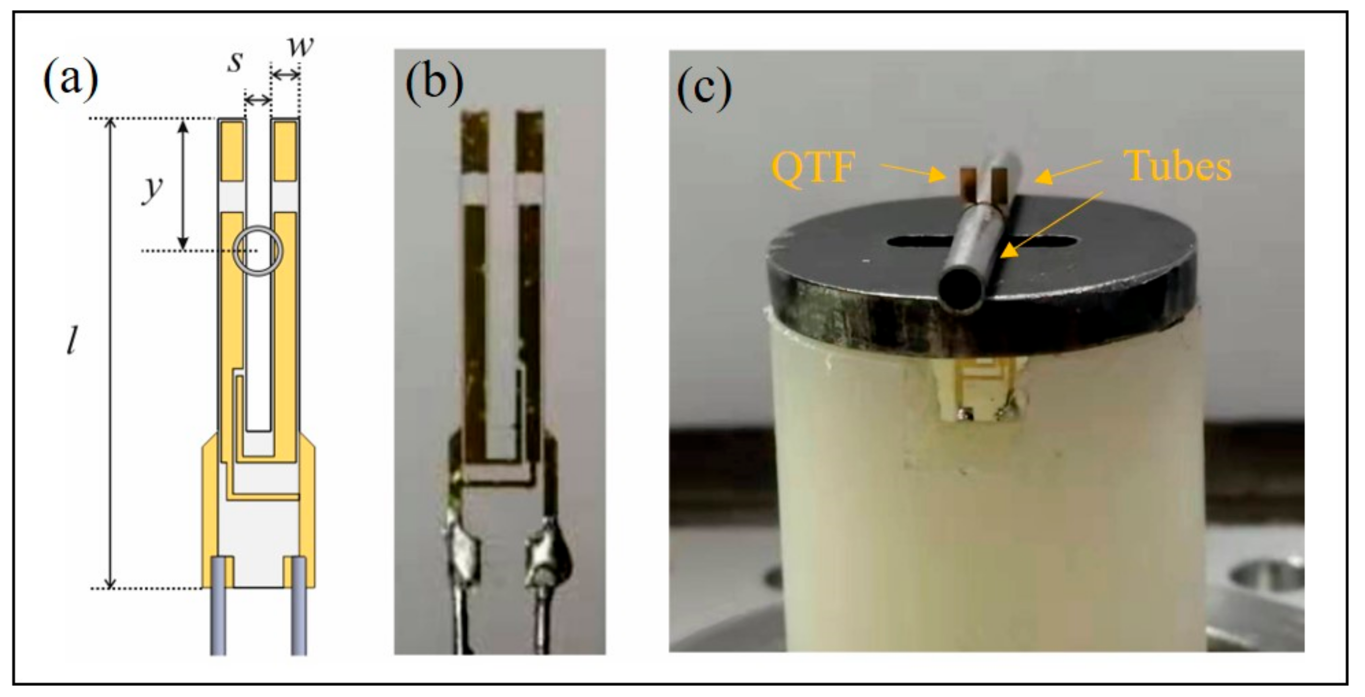
A custom QTF with a prong spacing of 800 µm was used to assemble the QEPAS spectrophone, as shown in Figure 2a,b [35]. The geometrical parameters (prong length and width and the prong spacing), and electrical parameters (resonance frequency, quality factor, and resistance) of the QTF, are listed in Table 1. As a comparison, the same parameters of a standard 32.7 kHz-QTF are also reported.
The prong spacing of custom QTF is 2.6 times larger than the standard 32.7 kHz-QTF (300 µm). This can be very useful when high-power lasers are used because a large prong spacing can reduce the portion of light hitting the internal surface of QTF prongs. When light touches the prong surface, a photothermal noise contribution is generated that can overwhelm the ultimate noise level, namely the thermal noise of the QTF, limiting the ultimate detection limit of the QEPAS sensor [36].

3. Optimization and Performance of the H2S Sensor

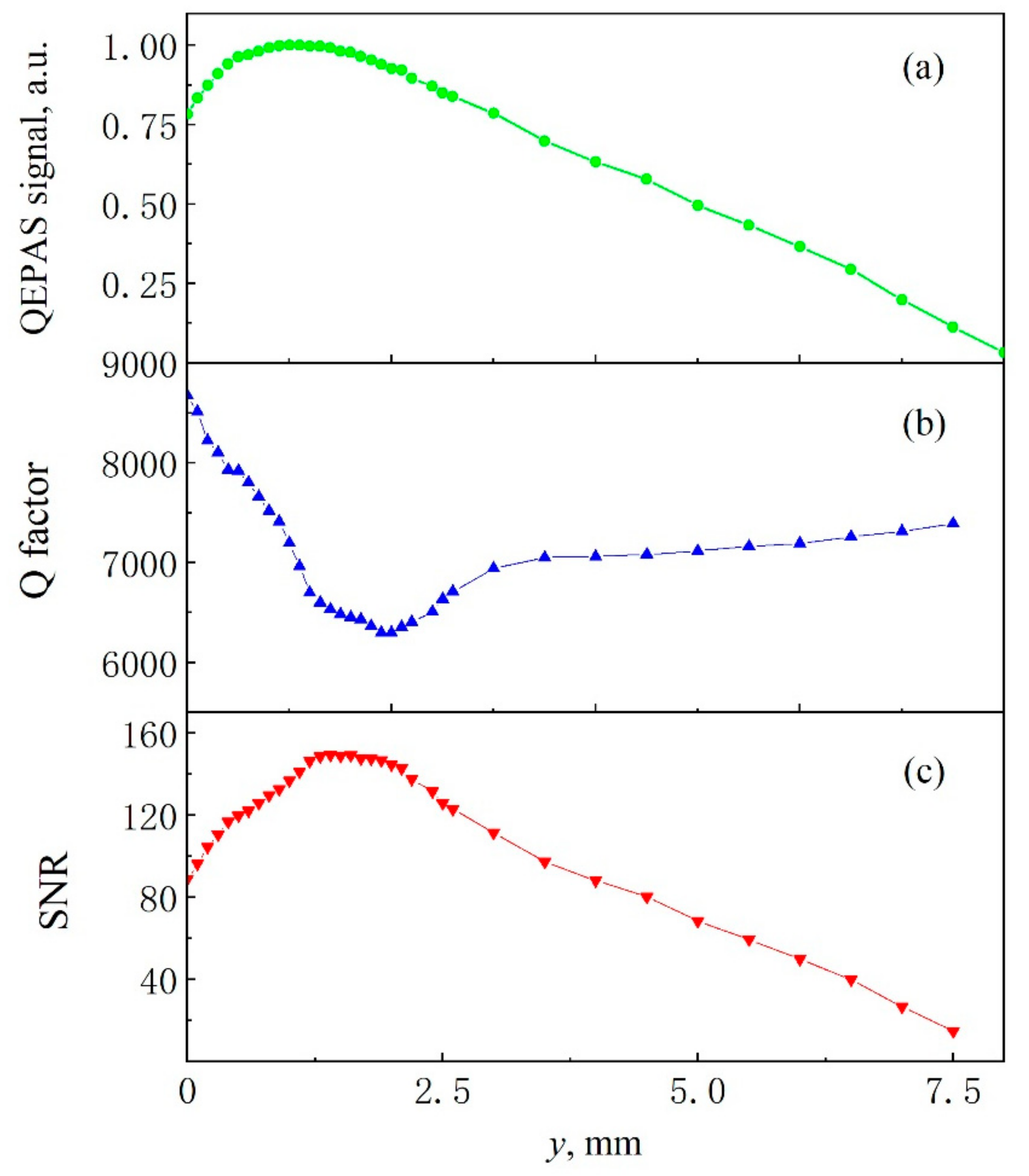
The QTF was coupled with a pair of resonator tubes to realize a QEPAS spectrophone, as shown in Figure 2c. As discussed, in on-beam configuration, the QTF is located between the tubes to probe the acoustic wave excited in the absorbing gas within the tubes. The internal diameter and the length of the two tubes influence the ultimate spectrophone performance [24,25]. For the custom QTF, Wu et al. [34] optimized the geometrical parameters. The study pointed out that both tubes must be 23 mm long and the optimal diameter must be 2.6 mm. In this way, the signal-to-noise ratio (SNR) increases by a factor of 40, compared to the case of a bare custom QTF. The results mentioned above are extremely useful in the design and assembling of the H2S QEPAS spectrophone. Hence, the geometrical parameters mentioned above were adopted in this work. The position of both tubes along the QTF axis, namely the axis parallel to the prong and passing between them, has to be optimized in terms of the QEPAS peak signal and noise. Hereafter, the QEPAS peak signal reported in all graphs corresponds to the maximum absorption in a spectral scan of the selected H2S absorption line. The position of tubes has to be moved from the top to the bottom, along the QTF axis between the two prongs. The distance between the center position of the tube and the top of the tuning fork is defined as y. The investigation was performed while a certified concentration of 50 ppm of H2S in nitrogen was flowing within the ADM, at atmospheric pressure. The experimental QEPAS peak signals, normalized to the highest value, at different tubes positions along the QTF axis are shown in Figure 3a. The QTF signal reaches its maximum value at y = 1.0 mm, then the signal decreases slowly with the increase of y, retracing the lateral displacement of a vibrating cantilever.
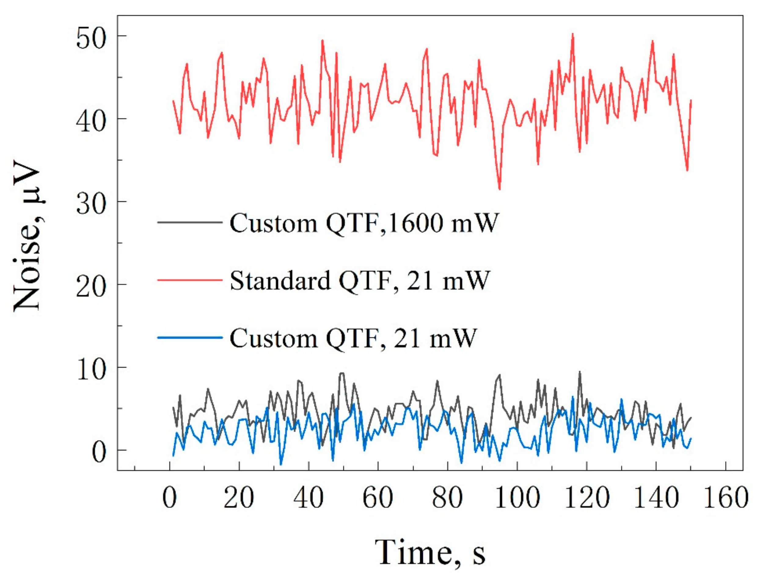
For each position, the QTF quality factor has been measured as a function of y, as shown in Figure 3b. When tubes are located close to the top of prongs (y = 0), the quality factor is the same as the bare QTF. The quality factor drops down to ~6300 at y = 2.0 mm, 1.0 mm far from where the maximum QEPAS signal has been recorded. Figure 3c reports the signal-to-noise ratio (SNR) as a function of tube position. When 0 < y < 1.4, the SNR increases until it reaches the maximum at y = 1.4 mm. When 1.4 mm < y < 2.1 mm, SNR changes less than 1% with respect to the maximum value. At y > 2.1, SNR gradually reduces. Hence, the QEPAS signal and the SNR reaches maximum values at different y values. This behavior can be explained by analyzing the noise level of the spectrophone. It has been acquired while pure nitrogen was flowing within the ADM, at atmospheric pressure. The noise measured when both the laser power was boosted at 1.6 W and when the amplifier was off is reported in Figure 4. As a comparison, the noise acquired with the spectrophone composed of the standard QTF and tubes 4.0 mm-long with an internal diameter of 800 µm is also reported, with the same experimental conditions [25].
When the optical power of the erbium-doped fiber amplifier is 1.6 W, the noise floor is 44 µV when the 32.7 kHz QTF-based spectrophone is used, 12.6 times higher than that measured for custom QTF-based spectrophone (3.5 µV). Hence, the ultimate noise level of the 32.7 kHz QTF-based spectrophone is clearly dominated by the photothermal noise contribution. With the custom QTF-based spectrophone, the noise floor increases from 2.32 µV to 3.5 µV when the laser power passes from 21 mW to 1.6 W, allowing to affirm that the photothermal noise contribution is negligible. The 1σ noise level of the custom QTF-based spectrophone increases from 2.1 μV to 2.6 μV when the power of the exciting laser varies from milliwatt level (21 mW) to watt level (1.6 W). These values are comparable with the theoretical thermal noise of 2.3 μV, estimated by using [19]:
V r m 2 = R g 4 K B T R Δ f ,
where Rg is the feedback resistor of the QTF amplifier, KB is the Boltzmann constant, T is the temperature, Δf = 0.833 Hz, and R is the electrical resistance. By modeling the QTF as an RLC series circuit, the electrical resistance can be related to the quality factor by the following relation:
R = 1 Q L C ,
where L is the QTF inductance and C its capacitance. Thus, variations of the quality factor affect the electrical resistance that in turn causes changes in the thermal noise. Thus, SNR in Figure 2c is affected both by QEPAS signal and quality factor, which have different trends as a function of y. This explains why SNR and QEPAS signal reaches their maximum values at different y positions.
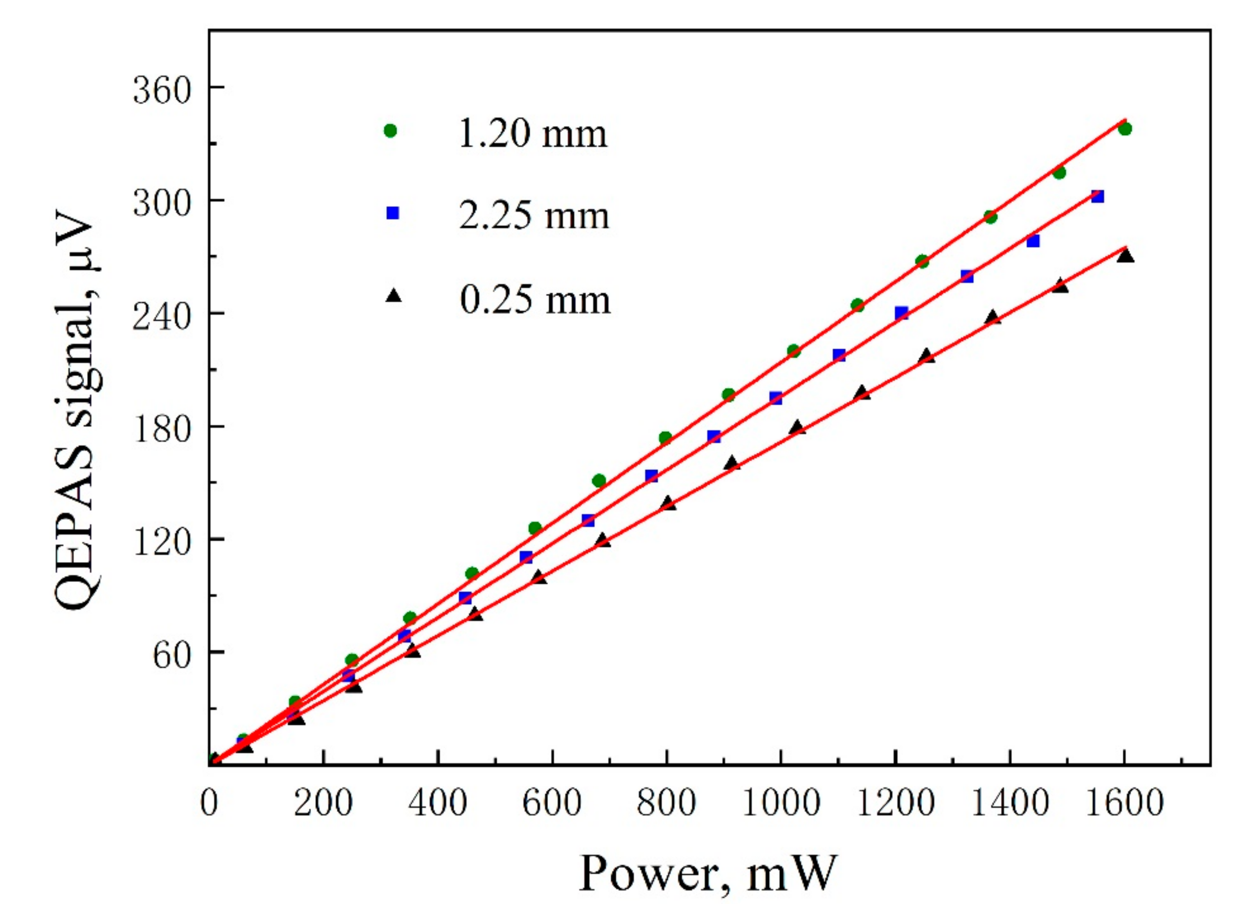
The variation of QEPAS signal with the optical power of the exciting laser in the range 5 mW–1.6 W has been recorded at three different positions of tubes, y = 250 µm, 1.2 mm, and 2.25 mm. The results are plotted in Figure 5.
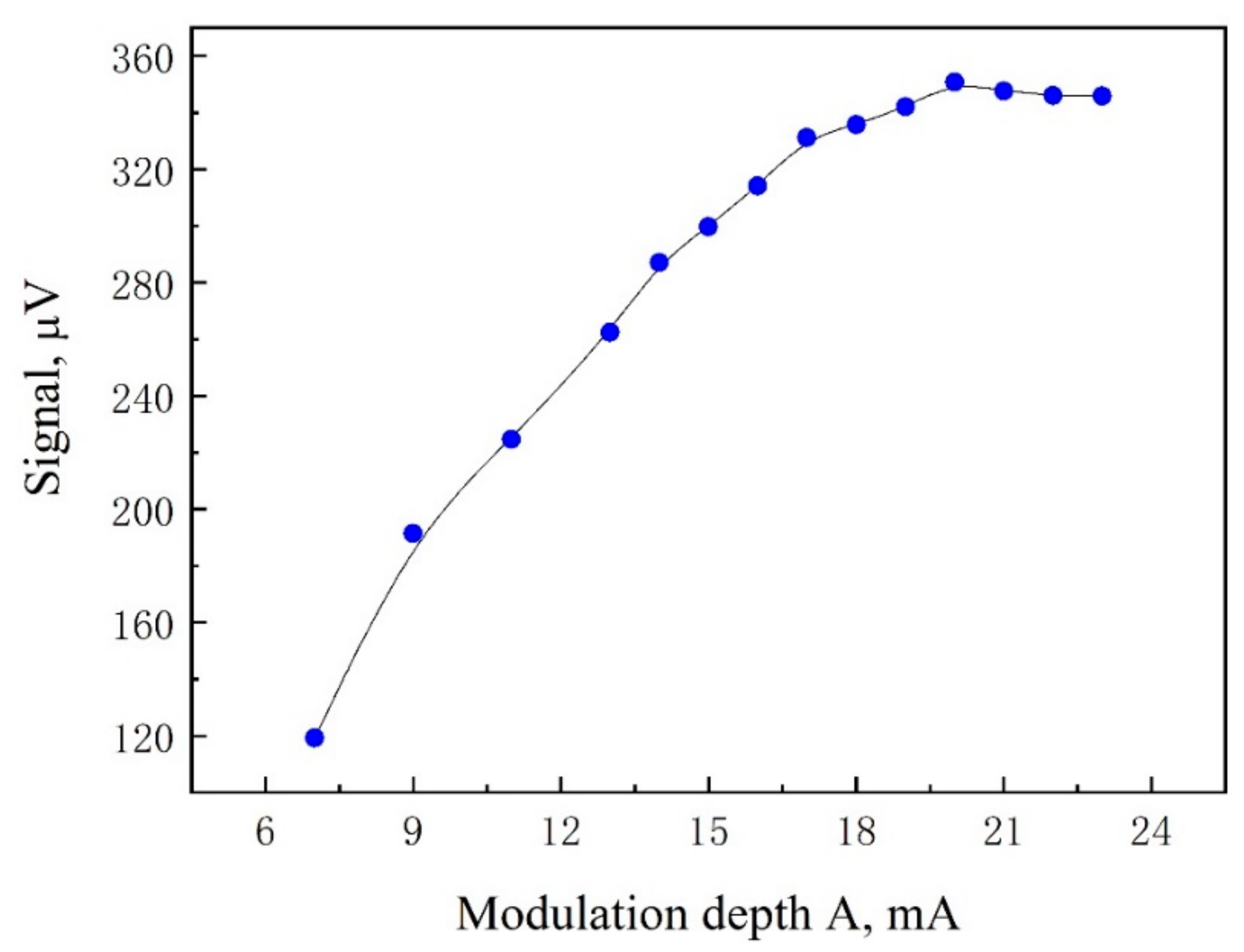
For each position, the QEPAS signal scales linearly with the laser power, with different slopes. Thus, at high optical power levels, the choice of the optimized tube position is more critical. Hereafter, the tubes will be located at y = 1.4 mm, where the maximum SNR was recorded. In the 2f-WMS technique, the QEPAS signal intensity is related to the laser modulation depth and the linewidth of the gas absorption line. Hence, the laser modulation depth was optimized at atmospheric pressure. The laser modulation depth optimization was carried out by varying the amplitude modulation of the current dither while a certified concentration of 50 ppm H2S:N2 was flowing in the ADM. The QEPAS peak signals of the 2f-WMS scan were acquired at different laser current modulation depths. The results are depicted in Figure 6.
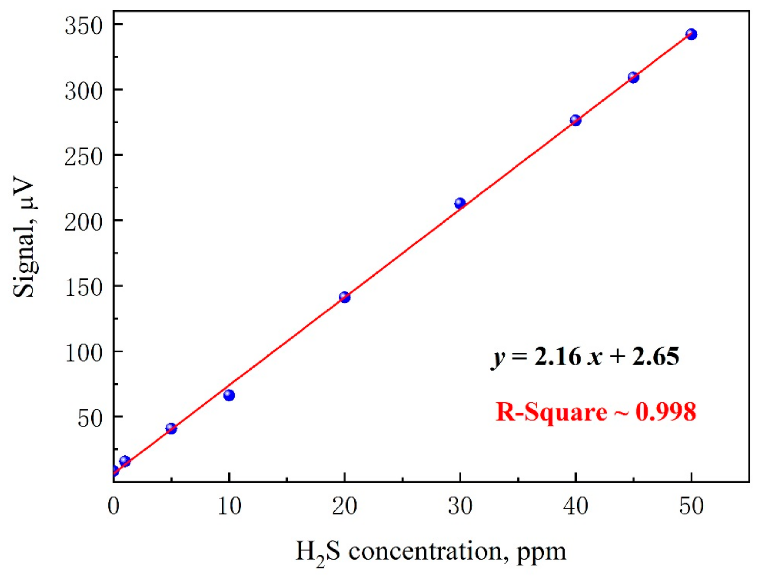
The QEPAS signal rapidly rose as the current modulation depth increased and reached its maximum at 20 mA, which corresponds to a wavelength modulation depth of 0.33 cm−1. Different H2S concentrations in the range 0.5–50 ppm were generated by using a gas mixer generator, starting from a certified 50 ppm H2S in N2 mixture and by using N2 as the diluting gas. The peak values of the 2f scans were recorded at different H2S concentrations. For each concentration, the low-frequency ramp for wavelength scanning was repeated 50 times, and the peak values were averaged and plotted in Figure 7 at different H2S concentrations.
The best linear fit returns an R-square value of ~0.998, assessing the linearity of the sensor system response to H2S concentration levels. The intercept of the linear fit is 2.65 µV, comparable with 1σ noise level measured previously. Thus, a minimum detection limit (1σ value) of 330 ppb was estimated, corresponding to a normalized noise equivalent absorption (NNEA) coefficient is 3.15 × 10⁻⁹ W·cm-1/(Hz)1/2, with a laser power of 1.6 W.
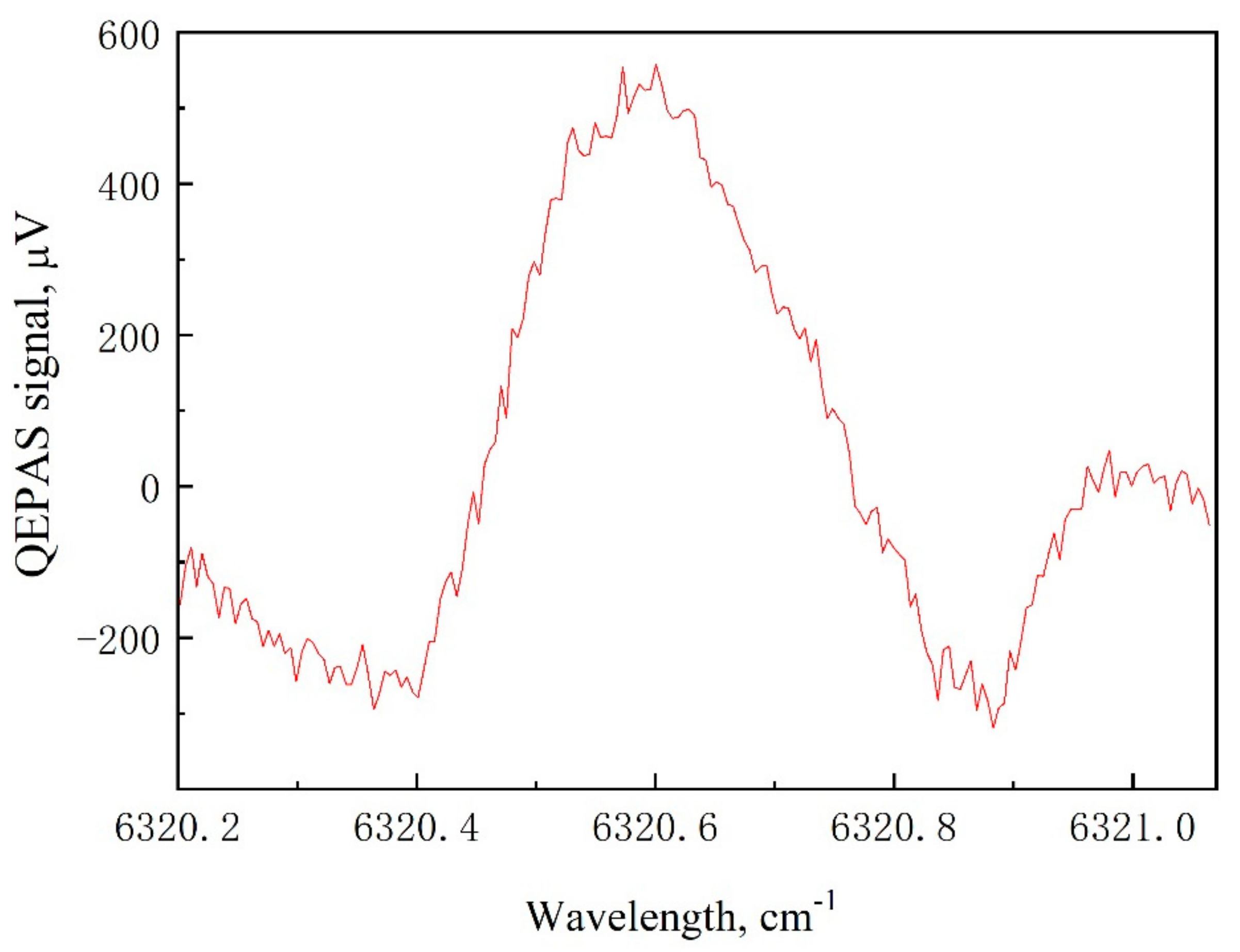
The high power QEPAS-based H2S sensor was employed for measuring H2S in a biogas sample. Biogas utilization has undergone great development in China as it is very important for resolving the country energy problem in rural areas. An anaerobic ferment digester is the key component of household biogas digester in which human waste, livestock manure, and organic waste can be converted into biogas. CH4 and CO2 are the main ingredients of the biogas. However, H2S is usually contained in biogas. The H2S concentration can reach 200 ppm for the biogas which is converted via livestock manure. As H2S is dangerous to human health, detecting the H2S concentration in biogas is very important. A sample bag was used to collect the biogas sample from a household biogas digester which is built in a livestock farm. The biogas was pumped into the detection unit by a pump. The gas flow and the pressure in the gas enclosure were set at 150 sccm and 760 Torr, respectively. A full 2f H2S QEPAS spectrum was obtained when the laser wavelength was scanned from 6320.2 cm−1 to 6321.1 cm−1, as shown in Figure 8, at the best operating conditions.
Based on the QEPAS sensor response curve in Figure 7, the estimated H2S concentration of the sample biogas is 78.2 ppm.

4. Conclusions

A sensitive H2S trace gas sensor based on the QEPAS technique was realized. With Watt-level high-power lasers used as photoacoustic exciting laser, a QEPAS spectrophone composed of a QTF with 800 µm-prong spacing and tubes with diameters of 2.6 mm prevents the generation of large noise contribution caused by the light touching tubes. In this condition, the ultimate noise level of the sensor is determined only by the QTF Johnson noise. The impact of tube position with respect to bare custom QTF on signal amplitude, background noise and SNR of the QEPAS sensor was investigated. The analysis allowed to determine the position of tubes maximizing the SNR, which is useful in the assembly of the QEPAS spectrophone. With a laser power of 1.6 W, the sensor achieved an H2S detection sensitivity of 330 ppb at atmospheric pressure and room temperature, corresponding to an NNEA of 3.15 × 10⁻⁹ W·cm−1/(Hz)1/2. To demonstrate the capability of the reported sensor system for in-situ measurements, the calibrated QEPAS sensor was used to measure H2S in a biogas sample from a household biogas digester.

Author Contributions

F.Z. and H.W., methodology; L.D., software; Y.G., L.Y., Y.Y., J.L., and J.R., experiments, software and data curation; S.d.R. and A.Z., formal analysis; P.P. and L.D., investigation and data curation; F.Z. and H.W., writing—original draft preparation; L.D., writing—review and editing; H.W. and L.D., supervision and project administration.

Funding

This research was funded by National Key Research and Development Program of China (No. 2017YFA0304203); National Natural Science Foundation of China (Grants #61622503, 61805132, 61575113, 11434007); Scientific Research Foundation (No. 227545028); Changjiang Scholars and Innovative Research Team in University of Ministry of Education of China (No. IRT_17R70); 111 project (Grant No. D18001), Outstanding Innovative Teams of Higher Learning Institutions of Shanxi; Shanxi “1331 Project”key subjects construction; Scientific and Technological Innovation Programs of Higher Education Institutions in Shanxi (No. 2019L0028); National Training Program of Innovation and Entrepreneurship for Undergraduates (201910108001, 2019017287); Applied basic research program of Shanxi province (No. 201801D221174).

Conflicts of Interest

The authors declare no conflict of interest.

References

  1. Pandey, S.K.; Kim, K.H.; Tang, K.T. A review of sensor-based methods for monitoring hydrogen sulfide. TrAC-Trends Anal. Chem. 2012, 32, 87–99. [Google Scholar] [CrossRef]
  2. Barsan, M.E. NIOSH Pocket Guide to Chemical Hazards; NIOSH Publications: Washington, DC, USA, 2007. [Google Scholar]
  3. Wu, H.; Dong, L.; Liu, X.; Zheng, H.; Yin, X.; Ma, W.; Zhang, L.; Yin, W.; Jia, S. Fiber-Amplifier-Enhanced QEPAS sensor for simultaneous trace gas detection of NH3 and H2S. Sensors 2015, 15, 26743–26755. [Google Scholar] [CrossRef] [PubMed] [Green Version]
  4. Shu, J.; Qiu, Z.; Lv, S.; Tang, D. Cu2+-doped SnO2 nanograin/polypyrrole nanospheres with synergic enhanced properties for ultrasensitive room-temperature H2S gas sensing. Anal. Chem. 2017, 89, 11135–11142. [Google Scholar] [CrossRef] [PubMed]
  5. Tangerman, A. Determination of volatile sulphur compounds in air at the parts per trillion level by Tenax trapping and gas chromatography. J. Chromatogr. A 1986, 366, 205–216. [Google Scholar] [CrossRef]
  6. Puacz, W.; Szahun, W.; Linke, K. Catalytic determination of sulfide in blood. Analyst 1995, 120, 939–941. [Google Scholar] [CrossRef]
  7. Lawrence, N.; Davis, J.; Jiang, L.; Jones, T.; Davies, S.; Compton, R. The electrochemical analog of the methylene blue reaction: A novel amperometric approach to the detection of hydrogen Sulfide. Electroanalysis 2000, 12, 1453–1460. [Google Scholar] [CrossRef]
  8. Ehman, D. Determination of parts-per-billion levels of hydrogen sulfide in air by potentiometric titration with a sulfide ion-selective electrode as an indicator. Anal. Chem. 1976, 48, 918–920. [Google Scholar] [CrossRef]
  9. Hodgkinson, J.; Tatam, R. Optical gas sensing: A review. Meas. Sci. Technol. 2013, 24, 012004. [Google Scholar] [CrossRef] [Green Version]
  10. Wu, H.; Yin, X.; Dong, L.; Jia, Z.; Zhang, J.; Liu, F.; Ma, W.; Zhang, L.; Yin, W.; Xiao, L.; et al. Ppb-level nitric oxide photoacoustic sensor based on a mid-IR quantum cascade laser operating at 52 °C. Sens. Actuators B Chem. 2019, 290, 426–433. [Google Scholar] [CrossRef]
  11. Dong, L.; Li, C.; Sanchez, N.; Gluszek, A.; Griffin, R.; Tittel, F. Compact CH4 sensor system based on a continuous-wave, low power consumption, room temperature interband cascade laser. Appl. Phys. Lett. 2016, 108, 011106. [Google Scholar] [CrossRef] [Green Version]
  12. Cristina, P. Breathing Disorders Using Photoacoustics Gas Analyzer. J. Med. Imaging Health Inform. 2016, 6, 1893–1895. [Google Scholar]
  13. Chen, K.; Zhang, B.; Liu, S.; Jin, F.; Guo, M.; Chen, Y.; Yu, Q. Highly sensitive photoacoustic gas sensor based on multiple reflections on the cell wall. Sens. Actuators A Phys. 2019, 290, 119–124. [Google Scholar] [CrossRef]
  14. Ma, Y.; He, Y.; Tong, Y.; Yu, X.; Tittel, F. Quartz-tuning-fork enhanced photothermal spectroscopy for ultra-high sensitive trace gas detection. Opt. Express 2018, 26, 32103–32110. [Google Scholar] [CrossRef] [PubMed] [Green Version]
  15. He, Y.; Ma, Y.; Tong, Y.; Yu, Y.; Tittel, F. Ultra-high sensitive light-induced thermoelastic spectroscopy sensor with a high Q-factor quartz tuning fork and a multipass cell. Opt. Lett. 2019, 44, 1904–1907. [Google Scholar] [CrossRef]
  16. Nägele, M.; Sigrist, M. Mobile laser spectrometer with novel resonant mult-pass photoacoustic cell for trace gas sensing. Appl. Phys. B 2000, 70, 895–901. [Google Scholar] [CrossRef]
  17. Gagliardi, G.; Loock, H. Cavity-Enhanced Spectroscopy and Sensing; Springer: Berlin/Heidelberg, Germany, 2014; Volume 179. [Google Scholar]
  18. Elia, A.; Lugarà, P.; Di Franco, C.; Spagnolo, V. Photoacoustic techniques for trace gas sensing based on semiconductor laser sources. Sensors 2009, 9, 9616–9628. [Google Scholar] [CrossRef] [Green Version]
  19. Patimisco, P.; Scamarcio, G.; Tittel, F.; Spagnolo, V. Quartz-enhanced photoacoustic spectroscopy: A review. Sensors 2014, 14, 6165–6206. [Google Scholar] [CrossRef] [Green Version]
  20. Wu, H.; Dong, L.; Pei, K.; Sampaolo, A.; Patimisco, P.; Zheng, H.; Ma, W.; Zhang, L.; Yin, W.; Xiao, L.; et al. Simultaneous dual-gas QEPAS detection based on a fundamental and overtone combined vibration of quartz tuning fork. Appl. Phys. Lett. 2017, 110, 121104. [Google Scholar] [CrossRef] [Green Version]
  21. Wu, H.; Dong, L.; Yin, X.; Sampaolo, A.; Patimisco, P.; Ma, W.; Zhang, L.; Yin, W.; Xiao, L.; Spagnolo, V.; et al. Atmospheric CH4 measurement near a landfill using an ICL-based QEPAS sensor with V-T relaxation self-calibration. Sens. Actuators B Chem. 2019, 297, 126753. [Google Scholar] [CrossRef]
  22. Patimisco, P.; Sampaolo, A.; Dong, L.; Tittel, F.; Spagnolo, V. Recent advances in quartz enhanced photoacoustic sensing. Appl. Phys. Rev. 2018, 5, 011106. [Google Scholar] [CrossRef]
  23. Wu, H.; Dong, L.; Zheng, H.; Yu, Y.; Ma, W.; Zhang, L.; Yin, W.; Xiao, L.; Jia, S.; Tittel, F. Beat frequency quartz-enhanced photoacoustic spectroscopy for fast and calibration-free continuous trace-gas monitoring. Nat. Commun. 2017, 8, 15331. [Google Scholar] [CrossRef] [PubMed] [Green Version]
  24. Patimisco, P.; Sampaolo, A.; Zheng, H.; Dong, L.; Tittel, F.K.; Spagnolo, V. Quartz-Enhanced photoacoustic spectrophones exploiting custom tuning forks: A review. Adv. Phys. X 2016, 2, 169–187. [Google Scholar] [CrossRef]
  25. Dong, L.; Kosterev, A.; Thomazy, D.; Tittel, F. QEPAS spectrophones: Design, optimization, and performance. Appl. Phys. B 2010, 100, 627–635. [Google Scholar] [CrossRef]
  26. Patimisco, P.; Sampaolo, A.; Giglio, M.; Dello Russo, S.; Mackowiak, V.; Rossmadl, H.; Cable, A.; Tittel, F.K.; Spagnolo, V. Tuning forks with optimized geometries for quartz-enhanced photoacoustic spectroscopy. Opt. Express 2019, 27, 1401–1415. [Google Scholar] [CrossRef] [Green Version]
  27. Patimisco, P.; Borri, S.; Sampaolo, A.; Beere, H.; Ritchie, D.; Vitiello, M.; Scamarcio, G.; Spagnolo, V. Quartz enhanced photo-acoustic gas sensor based on a custom tuning fork and a terahertz quantum cascade laser. Analyst 2013, 139, 2079–2087. [Google Scholar] [CrossRef] [PubMed]
  28. Patimisco, P.; Sampaolo, A.; Mihai, L.; Giglio, M.; Kriesel, J.; Sporea, D.; Scamarcio, G.; Tittel, F.; Spagnolo, V. Low-loss coupling of quantum cascade lasers into hollow-core waveguides with single-mode output in the 3.7–7.6 μm spectral range. Sensors 2016, 16, 533. [Google Scholar] [CrossRef] [Green Version]
  29. Giglio, M.; Patimisco, P.; Sampaolo, A.; Scamarcio, G.; Tittel, F.K.; Spagnolo, V. Allan deviation plot as a tool for quartz-enhanced photoacoustic sensors noise analysis. IEEE Trans. Ultrason. Ferroelectr. 2016, 63, 555–560. [Google Scholar] [CrossRef]
  30. De Cumis, M.S.; Viciani, S.; Borri, S.; Patimisco, P.; Sampaolo, A.; Scamarcio, G.; De Natale, P.; D’Amato, F.; Spagnolo, V. Widely-tunable mid-infrared fiber-coupled quartz-enhanced photoacoustic sensor for environmental monitoring. Opt. Express 2014, 22, 28222–28231. [Google Scholar] [CrossRef] [Green Version]
  31. Spagnolo, V.; Patimisco, P.; Pennetta, R.; Sampaolo, A.; Scamarcio, G.; Vitiello, M.S.; Tittel, F. THz quartz-enhanced photoacoustic sensor for H2S trace gas detection. Opt. Express 2015, 23, 7574–7582. [Google Scholar] [CrossRef] [Green Version]
  32. HITRAN Database. Available online: https://hitran.org/ (accessed on 1 March 2009).
  33. Wu, H.; Dong, L.; Zheng, H.; Liu, X.; Yin, X.; Ma, W.; Zhang, L.; Yin, W.; Jia, S.; Tittel, F. Enhanced near-infrared QEPAS sensor for sub-ppm level H2S detection by means of a fiber amplified 1582nm DFB laser. Sens. Actuators B Chem. 2015, 221, 666–672. [Google Scholar] [CrossRef] [Green Version]
  34. Wu, H.; Sampaolo, A.; Dong, L.; Patimisco, P.; Liu, X.; Zheng, H.; Yin, X.; Ma, W.; Zhang, L.; Yin, W.; et al. Quartz enhanced photoacoustic H2S gas sensor based on a fiber-amplifier source and a custom tuning fork with large prong spacing. Appl. Phys. Lett. 2015, 107, 111104. [Google Scholar] [CrossRef] [Green Version]
  35. Patimisco, P.; Sampaolo, A.; Dong, L.; Giglio, M.; Scamarcio, G.; Tittel, F.K.; Spagnolo, V. Analysis of the electro-elastic properties of custom quartz tuning forks for optoacoustic gas sensing. Sens. Actuators B Chem. 2016, 227, 539–546. [Google Scholar] [CrossRef]
  36. Spagnolo, V.; Patimisco, P.; Borri, S.; Scamarcio, G.; Bernacki, B.E.; Kriesel, J. Mid-infrared fiber-coupled QCL-QEPAS sensor. Appl. Phys. B 2013, 112, 25–33. [Google Scholar] [CrossRef]
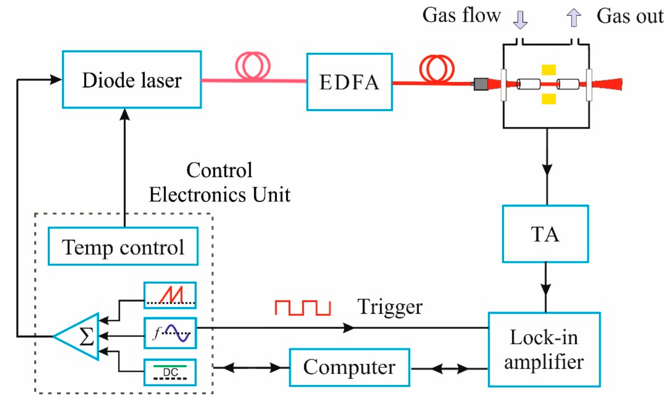
Figure 1. Schematic of the quartz-enhanced photoacoustic spectroscopy (QEPAS) sensor architecture. EDFA: Erbium-doped fiber amplifier. TA: Transimpedance amplifier.
Applsci 09 05347 g001
Figure 2. (a) Sketch of the custom QTF. (b) The photograph of the custom QTF. (c) The photograph of the acoustic detection module which includes a custom QTF and a pair of resonance tubes.
Applsci 09 05347 g002
Figure 3. (a) QEPAS peak signal, (b) quality factor and (c) signal-to-noise ratio as a function of the position of tubes y, measured starting from the top of the QTF. The data shown in the above figure were obtained while 50 ppm of H2S in N2 was flowing within the acoustic detection module, at high optical power (1.6 W), atmospheric pressure and room temperature.
Applsci 09 05347 g003
Figure 4. Noise level acquired for custom QTF-based spectrophone when the laser power is 21 mW (blue line) and 1600 mW (black line). Noise level for standard 32.7-kHz QTF-based spectrophone when the laser power is 1600 mW (red line). The data shown in the above figure was obtained while 50 ppm of H2S in N2 was flowing within the acoustic detection module, at atmospheric pressure and room temperature.
Applsci 09 05347 g004
Figure 5. QEPAS signal plotted as a function of the laser power acquired at three different tube positions, 0.25 mm (▲), 1.20 mm (•), and 2.25 mm (■). Solid lines are best fits to experimental data. The data shown in this figure were obtained while 50 ppm of H2S in N2 was flowing within the acoustic detection module, at atmospheric pressure and room temperature.
Applsci 09 05347 g005
Figure 6. QEPAS signal plotted at different current modulation depth. Solid line is a guide for eyes. The data shown in this figure were obtained while 50 ppm of H2S in N2 was flowing within the acoustic detection module, at high optical power (1.6 W), atmospheric pressure and room temperature.
Applsci 09 05347 g006
Figure 7. QEPAS signal as a function of H2S concentration (●). Red solid line is the best fit of the experimental data. The data shown in this Figure was obtained at high optical power (1.6 W), atmospheric pressure and room temperature while the tubes were equipped at y = 1.4 mm.
Applsci 09 05347 g007
Figure 8. 2f QEPAS scan of H2S absorption line in a biogas sample. The modulation depth and the power of the photoacoustic exciting laser were set at 0.33 cm−1 and 1.6 W, respectively. The data shown in this figure was obtained at atmospheric pressure and room temperature.
Applsci 09 05347 g008
Table 1. Geometrical (prong length, prong width, and prong spacing) and electrical parameters (resonance frequency, quality factor, and electrical resistance) of the custom quartz tuning fork (QTF) and a standard 32.7 kHz-QTF.
Prong ParametersElectrical Parameters
Spacing s
(mm)
Length l
(mm)
Width w
(mm)
Frequency
(Hz)
Q FactorResistance
(KΩ)
Standard QTF0.33.80.632.76812.000120
Custom QTF0.8100.972058500290