Article

A Study on the Improvement of Parallel Operation Characteristics of DC/DC Converter Using Improved Full-Duplex Communication Hardware

1
Department of Electrical Engineering, Chonnam National University, 77, Yongbong-ro, Buk-gu, Gwangju 61186, Korea
2
EV Components & Materials R&D Group, Korea Institute of Industrial Technology, 6 Cheomdan-gwagiro 208 beon-gil, Buk-gu, Gwangju 61012, Korea
3
School of Lift Engineering, Korea Lift College, 120, Unjeong1-gil, Geochang-eup, Geochang-gun, Gyeongsangnam-do 50141, Korea
*
Author to whom correspondence should be addressed.
Appl. Sci. 2019, 9(24), 5346; https://doi.org/10.3390/app9245346
Submission received: 27 November 2019 / Revised: 3 December 2019 / Accepted: 4 December 2019 / Published: 6 December 2019
(This article belongs to the Section Applied Industrial Technologies)

Abstract

:
Recently, as dependence and demand for electricity are rapidly increasing in all areas, including industry, methods for increasing capacity and reliability through parallel operations have been studied. In general, Modbus communication method with RS485 is used as a method of parallel operation for capacity increase. However, this method has a disadvantage in that it is a half-duplex communication system that cannot transmit and receive at the same time. However, the Modbus communication method is a half-duplex communication system where physical transmission and reception cannot be performed simultaneously. Therefore, as the number of power converters performing parallel operation increases, the communication period increases, which affects the power quality due to the decrease in control speed. Therefore, in this paper, we propose a hardware that can achieve a full-duplex communication method by a communication signal level to improve power quality. The characteristic of the proposed communication hardware is that the transmitter generates two-level signals for data transmission, but the receiver generates three-level electrical signals according to the state of the transmission data generated by the receiver. The generated three-level electrical signal is characterized in that the data transmission signal information of the transmitter and the data transmission signal information of the receiver occur at the same time. As a result, the communication speed is reduced by more than twice, which improves the power quality by improving the control characteristics when performing parallel operation.

1. Introduction

With the recent development of energy-based digitalization throughout society, dependence on electricity and demand for electricity are rapidly increasing. However, it is difficult to expand large-scale power plants such as fossil and nuclear power plants due to various issues such as the depletion of fossil energy, environmental problems, and social regulations [1,2]. Therefore, that a new power grid that includes new and renewable energy sources rather than fossil fuels and nuclear power generation methods used previously and a micro-grid have been proposed as an alternative.
The micro-grid can be classified into an AC (Alternating Current) and DC (Direct Current) distribution system. Recently, researches on DC distribution micro-grid with various advantages, such as improved efficiency by reducing the number of power conversions, have been actively conducted, compared to AC distribution systems. In particular, research on large-scale micro-grid systems is needed due to the recent surge in electricity consumption, dependence, and the need to increase the rate of renewable energy owing to environmental regulations. In order to operate micro-grid systems that can provide large-scale power, a power converter with a large capacity is required. However, there is a limit to configure them as a single power conversion stack. Therefore, parallel operation by a number of power converters is essential for the large capacity of micro-grid systems. Parallel operation of these power converters is generally performed by communication, and their performance is largely determined by the speed of communication [3,4,5,6,7].
In addition, parallel operation of power converters for parallel operation of a power converter to increase capacity is operated by various communication methods. The most common communication method is parallel operation using Modbus communication through RS485. In particular, according to Zhang, F [8], the Modbus protocol is widely adopted in power converters for renewable energy such that researches of linkage between the Modbus protocol and the IEC (International Electrotechnical Commission) 61850 protocol, used in a micro-grid, are steadily being conducted. However, Modbus communication has the limitation of half-duplex communication, which cannot be transmitted and received at the same time [9].
In the case of the half-duplex communication method, since the communication period increases proportionally as the communication object increases, there is a limitation to speed controlling. Decreased control speed not only reduces power quality, but can also cause critical troubleshooting where rapid protection cooperation is required in the event of a troubleshooting.
Various methods are being studied to overcome the limitations of this communication speed, and the typical method for this is a four-line communication method. For the four-line communication method, the communication line will be longer as the system becomes larger, which increases the relative financial burden. Therefore, research is needed on what has the ability to do the full-duplex communication method, but also transmit and receive at the same time through two-wire communication. Theoretically, implementing a full-duplex communication approach in a two-wire communication method would allow data to be processed at more than twice the speed of half-duplex communication [10,11]. Therefore, this paper suggests new communication hardware that enables full-duplex communication by the time division method while compensating the shortcomings of the existing serial communication system.
The proposed hardware for communications can detect incoming signals at the same time as multiple devices transmit signals to the same communication line. If it is possible to send and receive signals simultaneously, it is possible to quickly control not only a number of power converters but also other devices, and to respond quickly to incident. It is also expected to improve load sharing imbalances and problems with circulating currents that may arise in systems that require parallel operation [12,13,14]. Also, the voltage at the communication line is generated by transmission data from the transmitter and transmission data signals from the receiver. Thus, high security is expected as signal information from communication lines can only be analyzed with two devices that communicate with each other. To verify the validity of the proposed communication hardware, load sharing simulation was performed using PSIM, Powersim’s simulation tool. In addition, the load-sharing experiment of the power converter with the proposed communication hardware confirmed that a stable parallel operation was performed.

2. Parallel Operation of the Power Converter

2.1. Parallel Operation System

Figure 1 shows the equivalent circuit for analyzing the power-sharing characteristics of n   parallel connected power converters [15].
In Figure 1, V 1 to V n are the initial setting output voltage of number of n power converters, with each power converter having the same value. Z s e t + Δ Z 1 to Z s e t + Δ Z n is the line resistance between the output stage of the power converter consisting of n and the load resistance, and R L represents the load resistance. The output current divided by the n power converter is I 1 through I n . For the convenience of calculation, power current I 1 and I n are obtained under the assumption that there are only two power converters [16].
I 1 = V 1 V 2 R L + V 2 Z s e t + Δ Z 1 R x
I 2 = V 2 V 1 R L + V 1 Z s e t + Δ Z 2 R x
R x is as follows in Equation (3)
R x = Z s e t Δ Z 1 + Δ Z 2 R L + Δ Z 1 × Δ Z 2
If a parallel module is sharing the same current, it is I 1 = I 2 , and from Equations (1) and (2) the following Equation (4) can be obtained.
Z s e t V 2 × Δ Z 1 V 1 × Δ Z 2 = 2 R L × V 2 V 1
In assumption that the initial setting output voltage of each module is the same in Equation (4), it should be Z s e t + Δ Z 1 = Z s e t + Δ Z 2 . However, Z s e t + Δ Z 1 and Z s e t + Δ Z 2 do not match, indicating that the initial setting output voltage V 1 , V 2 must be controlled in order to share the same power current.

2.2. Voltage Drop Method

The voltage drop method relies on the drop characteristics of the output voltage to control the load sharing [17,18,19]. This method reduces the output voltage in proportion to the load current being shared, so that each module independently controls the load sharing without using the communication line of current information under the paralleled power converters. This method has poor current distribution characteristics in low power areas. Also, it is difficult to distribute current between parallel modules with different power ratings or poor load regulation characteristics [20,21].

2.3. Average Current Method

The average current method allows the current monitor of each power module to drive the common distribution bus through a resistor [22,23]. The control amplifier senses the presence of a current difference across the resistor, adjusts the load current imbalance, and adjusts the current command value accordingly [24]. This configuration performs accurate current distribution, but has the disadvantage that sometimes the distribution bus is shorted or the power supply does not operate.

2.4. Method by Serial Communication

Systems that support remotely monitored or controlled services have emerged for the efficient operation of power facilities such as micro-grid, and power protocols are needed to process various information of the system generated from power equipment. Unlike communication protocols typically used in computers, power protocols require reliable communication networks; high data integrity, data consistency, and fast response times are important. As a result, protocol limitations exist according to the specifications of power devices or systems, and various protocols have been developed to satisfy various elements required in the power system.
A brief summary of the purpose of each protocol used in the power system is as follows. There is the DNP (Distributed Network Protocol) 3.0 protocol, an industrial protocol utilized in existing power systems, and the IEC 61850 protocol, which is gradually extended from the current substation automation purpose to the power utility automation purpose. In addition, the control area network (CAN) and IEEE (Institute of Electrical and Electronics Engineers) 1451 are used for simple sensor data measurement, and the Modbus protocol is used for simple data acquisition and control in distributed power or renewable energy sources. Table 1 shows communication specifications of power converters for renewable energy power converter manufacturers, which are used in various renewable energy systems.
As can be seen from Table 1, power converters of many manufacturers still adopt the Modbus protocol. Accordingly, the basic driving method for the parallel operation method using the Modbus protocol adopted by many manufacturers is described below.
If the line impedance of the power converter performing voltage control is assumed to be similar, the same load current can be supplied to all the power converters by performing the output voltage control [25,26]. However, in real systems, the difference in track impedance and characteristics of the device causes circulating currents between the power converters, and as the load increases, it causes a breakdown by increasing unbalance currents [27]. Therefore, it is advisable to configure each module with a current controller to solve these problems [28,29]. In short, this means that in a parallel operation control method using serial communication, the master module must transmit current command generated through voltage control to the slave module. As devices increase as shown in Figure 2a, master–slave communication using Modbus communication increases the overall communication cycle, as shown in Figure 2b. If the communication cycle increases, the number of power converters capable of stable parallel operation is limited. Therefore, high-speed communication is essential for large capacity through stable parallel operation of the power converter.

3. Proposed Communication Hardware

Proposed Communication Hardware Configuration

Figure 3 shows this paper’s proposal: the three-level communication hardware. Three-level communication hardware enables full-duplex communication in a two-wire communication approach. Communication transmission signals occur depending on the on/off status of switches Q 1 and Q 2 . When both Q 1 and Q 2 are switched off, the output is high impedance status and cannot function at the communication line. When Q 1 is turned on and Q 2 is turned off, it transmits the binary serial communication value “1”, at which point V s becomes V d c . Conversely, when Q 1 is turned off and Q 2 is turned on, the serial communication binary value “0” is sent and V s is set to zero. However, the V L voltage appears in three levels by output impedance resistance and the output level of the counterpart device. Figure 4 shows the three-level communication hardware configuration for two-way communication. It is assumed that on the proposed topology, the impedance of the communication line is ignored because the output impedance is bigger than that of the communication line. The received voltages V L 1 and V L 2 of Module 1 and 2 are not determined by the transmit-side voltage or the receive-side voltage, but by each other’s transmission-side voltage and the receive-side voltage status. In other words, if the two transmit-side voltages are equal, when the transmit voltage is detected, and if the two transmit-side voltages are different, the voltage equivalent to half of the transmit voltage is detected. Due to this logic structure, the output voltage of the receiver appears to be three levels depending on the transmission information of the transmitter and receiver.
Therefore, the received information can be obtained by combining the receiving and transmitting information with the three-level voltage formed according to the transmission status of the transmitter and the receiving side.
Figure 5 shows a circuit diagram for obtaining incoming information from the generated three-level voltage. As shown in the figure, the signal V H L is generated first through the exclusive logic of V H and V L . In addition, the generated V H L and the transmission signal of the transmitting side module will be configured again as an exclusive logic so that the final incoming data RX can be entered.
Figure 6 shows the waveform when operating in full-duplex communication mode of Module 1 and Module 2 using the 3-level communication hardware shown in Figure 4. In order to clarify the interpretation, the two transmission signals, V s 1 and V s 2 are expressed as having a 90° phase difference as shown. In this case, as discussed earlier, the transmission side voltage and the receive side voltage will be displayed at different levels by the other side’s information. V L 1 generated by the transmission voltages V s 1 , V s 2 of Module 1 and 2 is shown in Figure 6. V H L signals generated through the exclusive logic of P 1 and P 2 signals are obtained through a photo-coupler which will be in the form of twice the transmission frequency. When the generated V H L signal and the transmission signal V s 1 of Module 1 are taken with exclusive logic, the transmission signal TX of Module 2 is finally extracted.

4. Simulation and Experiment Results

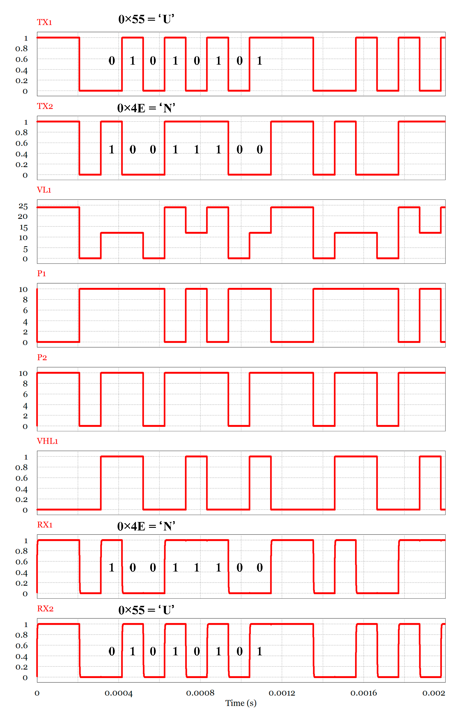
4.1. Proposed Three-Level Communication Simulation

Figure 7 is a simulation circuit diagram for verifying the validity of the proposed communication scheme. The simulation circuit consists of a half-bridge inverter for communication signal generation and a detector for three-level voltage detection. The photo-coupler in the detector was modeled using a voltage sensor and a comparator. In addition, it consists of an exclusive OR circuit that can detect the received signal, and the serial transmission signal is generated by using visual C in DLL (Dynamic Link Library).
In order to verify the validity of the communication hardware proposed in this paper, the simulation was carried out in two stages. First, we conducted a simulation to check the normal transmission and reception of the communication hardware proposed in this paper. Then, when the same protocol was used and the communication hardware proposed in this paper was applied, we attempted to verify whether the dynamic performance characteristics were improved compared to the existing communication methods.
Figure 8 shows the results of the simulation performed by setting 19,200 bps, 8-bit data, 1 stop bit, and non-parity to verify asynchronous serial communication. As shown in Figure 8, the transmission signal V s 1 of Module1 is an ASCII(American Standard Code for Information Interchange) code character ‘U’ having a hexadecimal number ‘0 × 55′ and the transmission signal V s 2 of Module 2 is an ASCII code character ‘N’ having a hexadecimal number ‘0 × 4E’. A three-level reception signal such as V L 1 is generated in the communication line by transmission data of ‘U’ and ‘N’ which are real-time full-duplex communication signals of the two modules. The voltage level of the communication line is determined by the transmission signals of both modules V s 1 and V s 2 . In order to obtain the transmission data on the transmission side, a combination of transmission data generated from the reception side and the three-level voltage of the communication line is required. That is, the reception information can be obtained by combining the V L 1 with the three-level voltage and the transmission signal TX of the reception side through the reception information extraction circuit. The feature of this method is that it can increase the communication speed compared with the existing serial communication method by simultaneously transmitting and receiving. Furthermore, it is impossible to separate another module’s transmission signal when the information of the transmission data of one module is absent from the three-level signal generated in the communication line. Even though the same ASCII character data is transmitted, since the communication is asynchronous, the three-level signal appearing on the communication line always appears in a different form. Also, when the receiver generates a transmitting signal for security when receiving an important signal, it is impossible for other devices to acquire accurate transmission data in the middle of the communication line. Therefore, the hardware proposed in this paper not only improves the communication speed compared to the existing method, but also excels in terms of the security of communication.

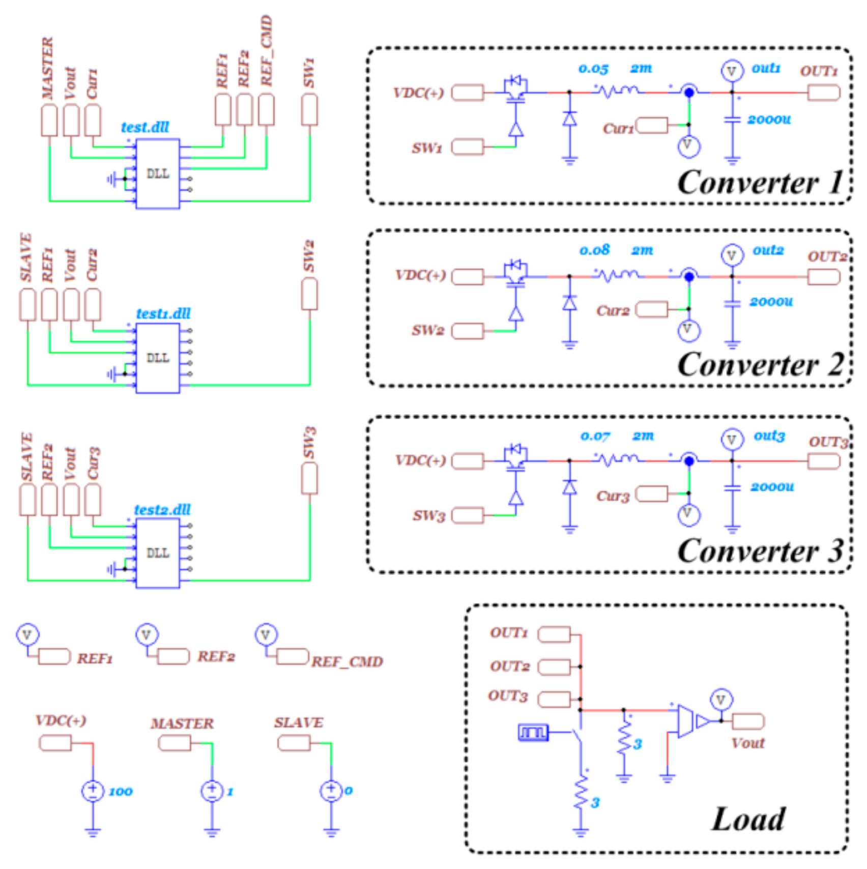
4.2. Parallel Operation Using Three-Level Communication Simulation

In a system such as a micro-grid system where large capacity of a power converter is required, there is a limitation in increasing the capacity to a single stack. Thus, to increase the capacity, the parallel operation technique by a number of power converters is required, and the control performance of parallel operation is greatly affected by the communication speed.
Figure 9 is a simulation circuit diagram for checking the superiority of the control characteristics when applying the proposed three-level communication method to a power converter configured for parallel capacity increase. The circuit configuration consists of one master converter performing voltage control and two converters performing current control. The current command transmission signal generated by the master converter was directly received from the slave DLL controlling the slave converter so that the load sharing operation could be performed. Simulation was conducted under the assumption that the protocol is composed of 19,200 bps, 2-byte data, and 2 byte CRC (Cyclic Redundancy Check) in order to verify the characteristic of the control by the communication speed in parallel operation. If the communication speed is too fast, it is difficult to compare the operation characteristics in the experiment. Therefore, both the simulation and the experiment were performed with the communication speed set to 19,200 bps. The communication cycle by protocol is implemented by using DLL, and simulation is performed by commanding the current command value according to the communication cycle to the slave converters.
Figure 10 shows the simulation result of the load sharing using the existing communication method and the communication method proposed in this paper. The order of the result waveform is listed above which is in the order of the output voltage, the reactor current of each converter, the current command value by communication, and the magnified waveform of the current command value. Regardless of the communication method, the controller of each converter is set identically, and the simulation is performed by changing the load from 50% to 100%. When load sharing is performed using existing serial communication, the load sharing is normally performed as shown in Figure 10a, but it was confirmed that the current command value of the converter was delayed by approximately 30 ms according to the communication cycle. As the number of power converters increases, the control delay increases due to communication, which causes a large current ripple and voltage ripple, and adversely affects power quality. However, when using the communication method with the proposed communication hardware as discussed in this paper, it is possible to control the load sharing more than twice as fast as the conventional method. As shown in Figure 10b, when the communication using the proposed communication hardware is performed, the power quality can be improved as compared to the existing communication method. Additionally, it can be predicted that the difference becomes larger as the number of power converters increases.

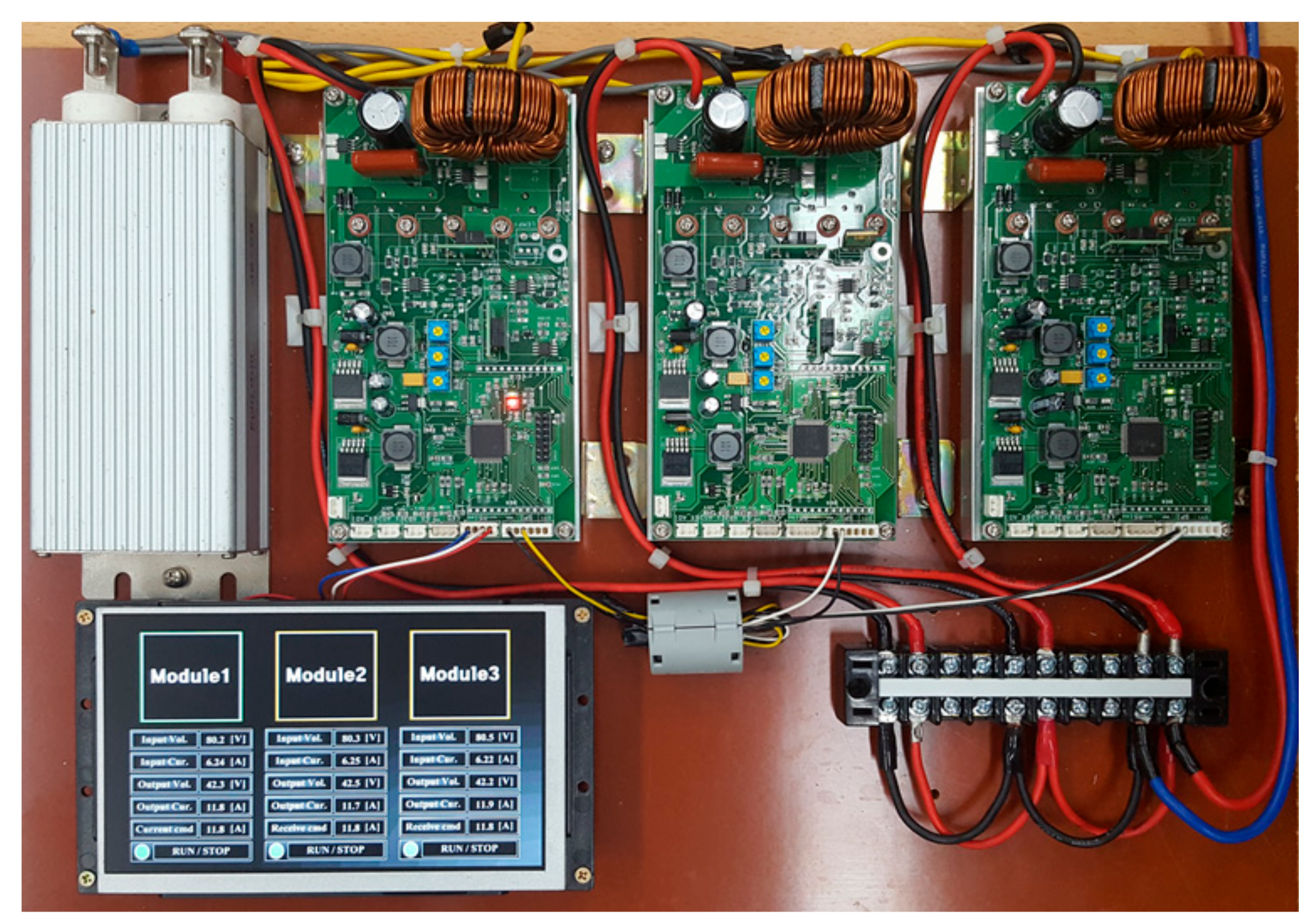
4.3. Experiment Result

In order to verify the communication hardware proposed in this paper, the system was constructed and the experiments were performed in the same way as the simulation.
Figure 11 shows a system with three-level communication hardware that can transmit and receive simultaneously in two-wire communication. The system consisted of three 500 W class power converters in parallel. The communication was conducted by constructing a protocol with 19,200 bps, 2-byte data, and 2-byte CRC as in the simulation.
Figure 12 shows the result waveform of communication hardware proposed in this paper. As for the order of the result waveform from the top, transmit data TX1 and TX2, communication line three-level voltage V L , and received data RX are listed. As shown in the figure, the two transmitters transmit data, but the synchronization is different, so the three-level voltage appearing on the communication line voltage V L is different. However, in the case of the received data, it can be confirmed that the data of the sender is correctly received. When parallel operation is performed using the three-level communication, as described above, it is two times faster than the conventional communication method. In order to verify this, the parallel operation experiment was conducted compared to the existing serial communication method. At this time, the controller characteristics of each power converter were set the same to check the control characteristics according to the load variation.
Figure 13 shows the resulting waveforms, when parallel operation is performed using the existing serial communication method and the three-level communication. The experiment proceeds under parallel operation by changing the load conditions (50%→100%→50%). The blue portion of the waveform indicates 50% load condition, and the red portion indicates a 100% load condition. The experiment compared the difference according to the communication method by checking the output voltage, the current waveform of the master converter, and the current waveform of the slave converter. The experiment was difficult to measure, clearly due to the current delay according to the communication method, if the communication speed is too fast. Thus, the experiment was conducted by constructing the protocol with 19,200 bps, 2-byte data, and 2-byte CRC.
Figure 13a shows the resulting waveform when parallel operation is performed by applying the existing serial communication method. As can be seen from the result waveform, the variation of the output voltage is large due to the delay of the current command value according to the communication speed when the load variation occurs. Figure 13b shows the result waveform when parallel operation is performed using the communication method proposed in this paper. As can be seen from the result waveform, the delay of the current command value is reduced and the variation of the output voltage is relatively stable compared to the conventional serial communication method.

5. Conclusions

In this paper, we proposed new communication hardware that is capable of full-duplex communication in two-wire communication and implemented parallel operation control using it.
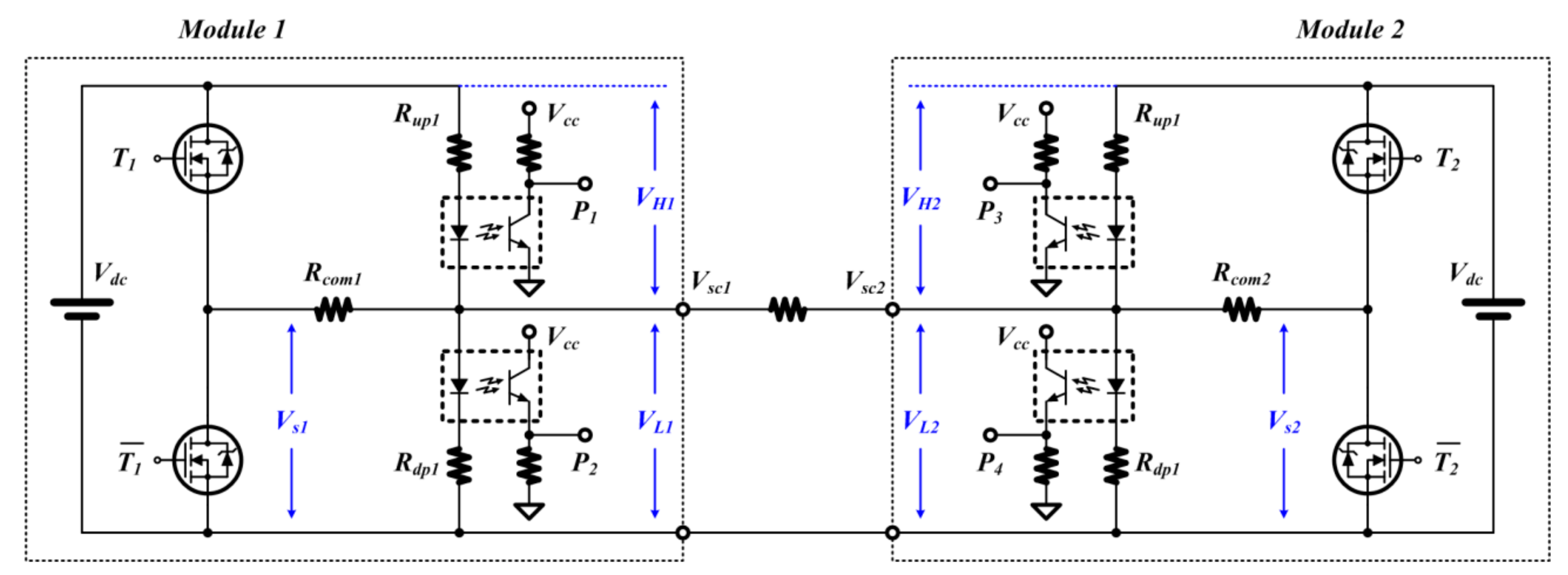
  • The communication transmitter generates two levels of signals for data transmission. However, due to the characteristics of the proposed communication hardware, three-level electrical signals are generated in the communication line according to the transmission data state of each module. The communication speed is improved by implementing full-duplex communication through the generated three-level electrical signal.
  • When performing parallel operation using the proposed communication hardware, power quality can be improved under the same conditions by controlling more than twice as fast as a serial communication method, such as a conventional Modbus communication. In addition, it is expected that the data protocol can be more simplified than the full-duplex communication by time division by implementing the full-duplex communication method by the hardware proposed in this paper.
  • It is expected that long-distance communication is possible by increasing the voltage of the transmission line by constructing the transmission circuit with a half-bridge structure.
  • The voltage of the communication line is generated by the transmitter transmission data and the receiver transmission data signal. Therefore, it is expected to be excellent in terms of security since only two devices communicating with each other can analyze signal information of a communication line.
In conclusion, the communication hardware proposed in this paper is expected to be actively applicable to the system requiring large capacity through parallel operation. It is also expected to improve load sharing imbalances and problems with circulating currents that may arise in systems that require parallel operation.

Author Contributions

Conceptualization, S.-K.L., S.-M.P., and S.-J.P.; Data curation, S.-K.L., H.-R.C., and S.-M.P.; Formal analysis, S.-K.L., H.-R.C., and S.-M.P.; Funding acquisition, S.-J.P.; investigation, S.-K.L. and S.-J.P.; Project administration, S.-J.P.; Writing—original draft, S.-K.L.; Writing—review and editing, H.-R.C. and S.-J.P.

Funding

This research was funded by the support of the Korea Institute of Industrials Technology as “Development of Chassis Platform for Semi-autonomous Electric Vehicle with EMS Function” (KITECH NW-19-0050).

Conflicts of Interest

The authors declare no conflicts of interest.

References

  1. Brook, B.W.; Alonso, A.; Meneley, D.A.; Misak, J.; Blees, T.; van Erp, J.B. Why nuclear energy is sustainable and has to be part of the energy mix. Sustain. Mater. Technol. 2014, 1, 8–16. [Google Scholar] [CrossRef] [Green Version]
  2. Karim, R.; Karim, M.E.; Muhammad-Sukki, F.; Abu-Bakar, S.H.; Bani, N.A.; Munir, A.B.; Kabir, A.I.; Ardila-Rey, J.A.; Mas′ud, A.A. Nuclear energy development in Bangladesh: A study of opportunities and challenges. Energies 2018, 11, 1672. [Google Scholar] [CrossRef] [Green Version]
  3. Guerrero, J.M.; Vasquez, J.C.; Matas, J.; de Vicuna, L.G.; Castilla, M. Hierarchical control of droop-controlled AC and DC microgrids—A general approach toward standardization. IEEE Trans. Ind. Electron. 2011, 58, 158–172. [Google Scholar] [CrossRef]
  4. Guo, X.Q.; Liu, W.; Lu, Z. Flexible power regulation and current-limited control of grid-connected inverter under unbalanced grid voltage faults. IEEE Trans. Ind. Electron. 2017, 64, 7425–7432. [Google Scholar] [CrossRef]
  5. Xia, Y.; Peng, Y.; Yang, P.; Yu, M.; Wei, W. Distributed Coordination Control for Multiple Bidirectional Power Converters in a Hybrid AC/DC Microgrid. IEEE Trans. Power Electron. 2017, 32, 4949–4959. [Google Scholar] [CrossRef]
  6. Xia, Y.; Wei, W.; Yu, M.; Wang, X.; Peng, Y. Power Management for a Hybrid AC/DC Microgrid with Multiple Subgrids. IEEE Trans. Power Electron. 2018, 33, 3520–3533. [Google Scholar] [CrossRef]
  7. Leng, D.; Polmai, S. Virtual Synchronous Generator Based on Hybrid Energy Storage System for PV Power Fluctuation Mitigation. Appl. Sci. 2019, 9, 5099. [Google Scholar] [CrossRef] [Green Version]
  8. Zhang, F.; Zhu, Y.; Yan, C.; Bi, J.; Xiong, H.; Yuan, S. A realization method of protocol conversion between Modbus and IEC 61850. Open J. Appl. Sci. 2013, 3, 18–23. [Google Scholar] [CrossRef] [Green Version]
  9. Ding, Z.; Krikidis, I.; Rong, B.; Thompson, J.S.; Wang, C.; Yang, S. On combating the half-duplex constraint in modern cooperative networks: Protocols and techniques. IEEE Wirel. Commun. 2012, 19, 20–27. [Google Scholar] [CrossRef]
  10. Sabharwal, A.; Schniter, P.; Guo, D.; Bliss, D.W.; Rangarajan, S.; Wichman, R. In-band full-duplex wireless: Challenges and opportunities. IEEE J. Sel. Areas Commun. 2014, 32, 1637–1652. [Google Scholar] [CrossRef] [Green Version]
  11. Bharadia, D.; McMilin, E.; Katti, S. Full duplex radios. In Proceedings of the ACM SIGCOMM’13, Hong Kong, China, 12–16 August 2013; pp. 375–386. [Google Scholar]
  12. Galloway, B.; Hancke, G.P. Introduction to Industrial Control Networks. IEEE Commun. Surv. Tutor. 2013, 15, 860–880. [Google Scholar] [CrossRef] [Green Version]
  13. Jin, C.; Wang, P.; Xiao, J.; Tang, Y. Implementation of hierarchical control in DC microgrids. IEEE Trans. Ind. Electron. 2014, 61, 4032–4042. [Google Scholar] [CrossRef]
  14. Chen, B.; Chen, C.; Wang, J.; Butler-Purry, K.L. Sequential Service Restoration for Unbalanced Distribution Systems and Microgrids. IEEE Trans. Power Syst. 2017, 33, 1507–1520. [Google Scholar] [CrossRef]
  15. Charalambous, A.; Hadjidemetriou, L.; Zacharia, L.; Bintoudi, A.D.; Tsolakis, A.C.; Tzovaras, D.; Kyriakides, E. Phase Balancing and Reactive Power Support Services for Microgrids. Appl. Sci. 2019, 9, 5067. [Google Scholar] [CrossRef] [Green Version]
  16. Augustine, S.; Mishra, M.K.; Lakshminarasamma, N. Adaptive Droop Control Strategy for Load Sharing and Circulating Current Minimization in Low-Voltage Standalone DC Microgrid. IEEE Trans. Sustain. Energy 2015, 6, 132–141. [Google Scholar] [CrossRef]
  17. Tayab, U.B.; Roslan, M.A.B.; Hwai, L.J.; Kashif, M. A review of droop control techniques for microgrid. Renew. Sustain. Energy Rev. 2017, 76, 717–727. [Google Scholar] [CrossRef]
  18. Shuai, Z.; Mo, S.; Wang, J.; Shen, Z.J.; Tian, W.; Feng, Y. Droop control method for load share and voltage regulation in high-voltage microgrids. J. Mod. Power Syst. Clean Energy 2016, 4, 76–86. [Google Scholar] [CrossRef] [Green Version]
  19. Shankar, R.; Pradhan, S.; Chatterjee, K.; Mandal, R. A comprehensive state of the art literature survey on LFC mechanism for power system. Renew. Sustain. Energy Rev. 2017, 76, 1185–1207. [Google Scholar] [CrossRef]
  20. Zhong, Q.-C. Robust Droop Controller for Accurate Proportional Load Sharing Among Inverters Operated in Parallel. IEEE Trans. Ind. Electron. 2013, 60, 1281–1290. [Google Scholar] [CrossRef]
  21. Li, Y.W.; Kao, C.N. An accurate power control strategy for power-electronics-interfaced distributed generation units operating in a low-voltage multibus microgrid. IEEE Trans. Power Electron. 2009, 12, 2977–2988. [Google Scholar]
  22. Ayyanar, R.; Giri, R.; Mohan, N. Active input-voltage and load-current sharing in input-series and output-parallel connected modular DC–DC converters using dynamic input-voltage reference scheme. IEEE Trans. Power Electron. 2004, 19, 1462–1473. [Google Scholar] [CrossRef]
  23. Karlsson, P.; Svensson, J. DC bus voltage control for a distributed power system. IEEE Trans. Power Electron. 2003, 18, 1405–1412. [Google Scholar] [CrossRef] [Green Version]
  24. Khadem, S.; Basu, M.; Conlon, M.; Khadem, M.S.K. Parallel operation of inverters and active power filters in distributed generation system—A review. Renew. Sustain. Energy Rev. 2011, 15, 5155–5168. [Google Scholar] [CrossRef] [Green Version]
  25. Al-Nussairif, M.; Bayindir, R.; Sanjeevikumar, P.; Mihet-Popa, L.; Siano, P. Constant Power Loads (CPL) with Microgrids: Problem Definition, Stability Analysis and Compensation Techniques. Energies 2017, 10, 1656. [Google Scholar] [CrossRef]
  26. Lu, X.; Guerrero, J.M.; Sun, K.; Vasquez, J.C.; Teodorescu, R.; Huang, L. Hierarchical Control of Parallel AC-DC Converter Interfaces for Hybrid Microgrids. IEEE Trans. Smart Grid 2014, 5, 683–692. [Google Scholar] [CrossRef] [Green Version]
  27. Tahir, S.; Wang, J.; Baloch, M.H.; Kaloi, G.S. Digital control techniques based on voltage source inverters in renewable energy applications: A Review. Electronics 2018, 7, 18. [Google Scholar] [CrossRef] [Green Version]
  28. Yao, W.; Chen, M.; Matas, J.; Guerrero, J.M.; Qian, Z.M. Design and analysis of the droop control method for parallel inverters considering the impact of the complex impedance on the power sharing. IEEE Trans. Ind. Electron. 2011, 58, 576–588. [Google Scholar] [CrossRef]
  29. Rocabert, J.; Luna, A.; Blaabjerg, F.; Rodrguez, P. Control of power converters in AC microgrids. IEEE Trans. Power Electron. 2012, 27, 4734–4749. [Google Scholar] [CrossRef]
Figure 1. Equivalent circuit of power sharing.
Applsci 09 05346 g001
Figure 2. Load sharing diagram through serial communication. (a) Power converter configuration for load sharing; (b) Modbus communication cycle.
Applsci 09 05346 g002
Figure 3. Proposed three-level communication hardware.
Applsci 09 05346 g003
Figure 4. Hardware configuration for three-level communication for bidirectional communication.
Applsci 09 05346 g004
Figure 5. Reception information extraction circuit.
Applsci 09 05346 g005
Figure 6. Simultaneous bidirectional communication waveforms.
Applsci 09 05346 g006
Figure 7. Three-level communication simulation schematic.
Applsci 09 05346 g007
Figure 8. Simultaneous bidirectional simulation results.
Applsci 09 05346 g008
Figure 9. Parallel operation simulation circuit diagram.
Applsci 09 05346 g009
Figure 10. Parallel operation simulation circuit diagram. (a) Resulting waveform using the existing communication method; (b) resulting waveform using the proposed communication method.
Applsci 09 05346 g010
Figure 11. Power converter system with three-level communication hardware.
Applsci 09 05346 g011
Figure 12. Simultaneous bidirectional communication experiment results.
Applsci 09 05346 g012
Figure 13. Parallel operation experiment waveform. (a) Parallel operation result waveforms applied to existing serial communication; (b) parallel operation result waveforms applied to three-level communication.
Applsci 09 05346 g013
Table 1. Communication method of power converter according to manufacturer.
ManufactureModel No.UsageCommunication MethodBaud Rate (bps)
ABBPVI String SeriesString InverterModbus RTU etc.19,200
LS isSV SeriesSolar InverterModbus RTU etc.1200–19,200
HuaweiSUN2000String InverterModbus RTU etc.19,200
FroniusSYMO SeriesString InverterModbus RTU etc.2400–19,200
Solar EdgeSE SeriesString InverterModbus RTU etc.9600–115,200

