Abstract
An improved neural network-based equalization method is proposed and experimentally demonstrated. The up-to-137 Gb/s transmission of four level pulse amplitude modulation (PAM-4) signals with 25 G class 850 nm optical devices is achieved over an in-house fabricated 40 cm optical backplane. An in-depth investigation is conducted regarding the impact of delayed taps and spans on equalization performance. A performance comparison of the proposed method with the traditional maximum likelihood sequence estimation (MLSE) and decision feedback equalization (DFE) is also undertaken. For the bit rate from 80 to 100 Gb/s, the proposed method achieves an adopted hard-decision forward error correction (HD-FEC) requirement at a received optical power (RoP) of −9 and −8 dBm, while DFE and MLSE cannot meet the HD-FEC requirement. When the bit rate increases from 120 to 137 Gb/s, the proposed equalization method still successfully maintains the acceptable system performance at an RoP of −4 and −2.5 dBm. Furthermore, the specific bit error rate (BER) performances for varied maximum achievable bit rate under different RoPs by applying MLSE and the proposed method are also analyzed. This provides an important potential solution to realize the future data centers.
1. Introduction
Recent rapidly grown data traffic in the information and communication networks require high capacity short-reach (<100 cm) interconnected technology inside information and communications technology (ICT) equipment such as servers, routers, and storage [1]. On the other hand, the continuous growth of computing power is a leading cause of improvements to server performance and is also responsible for expanding server consolidation by virtualization. Such consideration requires a high bandwidth data communication intra blade server, which is an aggregate of compact servers connected via the backplane whose data connection capacity depends on the backplane performance [2]. Optical interconnect technology is an attractive candidate for enlarging data connection capacity due to this technology’s high-speed transmission and low interference between signals [3]. Optical interconnect technology enables the use of a higher bandwidth backplane compared with electrical interconnection. At present, the standardization of the single-wavelength 100 Gb/s transmission systems is under considerations by Institute of Electrical and Electronics Engineers (IEEE) and Multi Source Agreement (MSA). It is of great significance to realize the transmission rate of over 100 G in backplane interconnection [4].
Recently, optical backplanes based on board-level optical polymer waveguides have attracted increasing attention in the field of optical interconnects, mainly because optical backplanes can become a key enabler for electro-optic integration, which allows for the seamless mating of numerous optical interfaces. Besides that, optical backplanes help to avoid cumbersome cable handling at a board level [5]. According to the development trend of optical interconnect technology predicted by International Business Machines Corporation (IBM) statistics, optical interconnect technology has entered the stage of the optical interconnection between sub-boards and boards [6]. Hence, optical backplane interconnection technology has emerged to prepare an optical waveguide layer on a standard printed circuit board (PCB) or to embed the optical waveguide as a sandwich in the PCB, thereby realizing optical signal interconnection. A large optical backplane with embedded graded-index glass waveguides and fiber-flex termination was studied in [7]. Chunhe Zhao proposed a hybrid bidirectional optical backplane with multiple bus lines [8]. A glass-based 40 cm optical backplane with 0.1 dB/cm insertion loss was fabricated by our group [9].
In order to achieve a high rate and maintain a low cost, it is expected that low-cost bandwidth level optoelectronic devices will still preferred to be used in optical backplane interconnection systems [10,11,12,13,14,15,16,17,18], so high spectrum efficiency modulation formats such as four level pulse amplitude modulation (PAM-4) and duobinary are being considered for introduction. Meanwhile, considering its high insertion loss and strong modal noise, the optical backplane transmission system can be regarded as a bandwidth-constrained system with a high insertion loss, so strong equalization algorithms are then required. Transmission at bit rates up to 50 Gb/s over 200 m of multimode fiber (MMF) assisted by decision feedback equalization (DFE) was demonstrated in [18]. The 850 nm laser-based transmissions of 112 Gb/s PAM-4 over 100 m optical multi-mode 4 (OM4 ) MMF assisted by maximum likelihood sequence estimation (MLSE) was experimentally demonstrated in [19]. Moreover, a 135 Gb/s discrete multitone (DMT) transmission using pre-distortion was realized in [20]. Pulse shaping was applied in [21,22] to achieve error-free 100 Gb/s PAM-4 transmission over a 100 m wideband fiber. However, all the receiving sensitivities of the above schemes were no less than −4 dBm at 100 Gb/s under the 7% hard-decision forward error correction (HD-FEC) threshold.
Machine learning has become popular and has attracted increasing attention from optical communities. Because of their powerful feature extraction and analysis capabilities, neural networks (NNs) have been applied into signal equalization and nonlinear compensation [23,24,25,26]. Elias Giacoumidis experimentally demonstrated about 2 dB quality factor (Q-factor) enhancement in terms of fiber nonlinearity compensation using an artificial neural network (ANN) for 40 Gb/s 16 quadrature amplitude modulation (16-QAM) coherent optical orthogonal frequency division multiplexing (CO-OFDM) at 2000 km of uncompensated standard single-mode fiber (SSMF) transmission [27]. Oleg S. Sidelnikov employed dynamic multi-layer perceptron networks for long haul transmission systems and demonstrated performance improvement and a significant superiority of neural network complexity over the digital back-propagation method [28]. Based on 20 GHz class optical components, Lilin Yi realized the single carrier 100 Gb/s transmission using a NN [29] and also concluded that an NN learning the inner rules of pseudo-random binary sequence (PRBS) would lead to overestimation.
In this paper, an improved neural network-based equalization method is proposed and experimentally demonstrated. The up-to-137 Gb/s transmission of PAM-4 signals with 25 G class 850 nm optical devices is achieved over an in-house fabricated 40 cm optical backplane. An in-depth investigation is conducted regarding the impact of delayed taps and spans on equalization performance. A performance comparison of the proposed method with the traditional MLSE and DFE is also undertaken. For the bit rate from 80 to 100 Gb/s, the proposed method achieves the adopted HD-FEC requirement at received optical powers (RoPs) of −9 and −8 dBm, while DFE and MLSE cannot meet the HD-FEC requirement. When the bit rate increases from 120 to 137 Gb/s, proposed equalization method still successfully maintains the acceptable system performance at RoP of −4 and −2.5 dBm. Furthermore, the specific bit error rate (BER) performances for a varied maximum achievable bit rate under different RoPs that apply MLSE and the proposed method are also analyzed. This provides an important reference for future system design. It is worth mentioning that, because our backplane has a large attenuation of 8.7 dB, in order to comprehensively study the performance of the system under different receiving optical powers, we used an independent 850 nm laser and an external modulator in the experiment. As the fabrication technology improves and insertion loss decreases, the proposed algorithm can also be applied to a backplane transmission system based on low cost vertical cavity surface emitting lasers (VCSELs).
2. Operation Principle of the Proposed NN-Based Equalization Scheme
Due to the strong linear and nonlinear abstract ability of neural networks, they can be used to restore kinds of signal distortion in optical fibers during the transmission through proper training. The schematic structure of the proposed NN-based equalizer is shown in Figure 1. It is a three-layer fully-connected network that consists of an input layer, two hidden layers and an output layer. Every circle is known as a neuron. Each neuron of the input layer represents a data sample, which is a vector of one-dimension data here. Each line denotes a multiplier that multiplies the output of the previous layer by the corresponding weight. Each neuron of the hidden layer and the output layer is a computing unit with summation and activation functions. The concrete relationship that lines and neurons represent can be expressed as:
where is the neuron of the previous layer, y is the neuron of the subsequent layer, is the corresponding weight, and parameter b is the bias. Though the bias is not plotted in the structure, it exists by default, as the essential unit only contains storage and always stores a value of 1. The bias unit is connected to all nodes in the next layer but has no input. f(∙) is an activation function that realizes nonlinearity modeling. The activation function of hidden layers is sigmoid here, while the output activation is purelin, as expressed below:
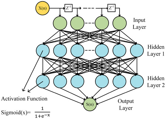
Figure 1.
The proposed neural network (NN)-based equalizer’s structure.
It can be found that the linear equalizer used in the traditional DFE is similar to the neural network equalization. However, there are differences in offset, hidden layer, and activation function. For example, the expression of feed forward equalization (FFE) can be expressed as:
where x(n) is the n-th received symbol, y(n) is the corresponding output signal, and is the weight for each sample in the sequence. Compared with Formula (1), there is no activation function and bias. The output here is the result of equalization, while the output of Formula (1) is the input of the hidden layer. This means DFE lacks the ability to overcome nonlinearities.
The steps of neural network equalization are as follows. The received data X(n) after resampling and timing recovery is firstly preprocessed before feeding the input of the NN. As is shown in Figure 2a, X(n) is delayed to several vectors of data. The number of delays is considered a delay tap. Delay span denotes the number of symbols during one delay operation. These vectors of data are then merged into a set of high dimensional data. Data from each dimension are input to the NN at the same time. Figure 2b shows the flow chart of the proposed algorithm and depicts the process of the training stage. Firstly, the weights and bias are initialized, and the convergence conditions of the NN are set. The weights obey a normal distribution with a mean of 0, a variance of 1, and a bias of 1. The number of iterations is 10. The convergence condition is that the value of mean-square error (MSE) is less than 0.0001. The correct target data S(n) are the output of the NN that come from the timing recovery. The NN estimates the target (n) from input by initial parameters. The MSE between (n) and S(n) is calculated and then reduced by the update of the NN. When the neural network satisfies the preset convergence conditions, the algorithm jumps out of this cycle, indicating the completion of the training stage for NN equalization. Before the test stage, the data are preprocessed in the same way as the training stage. During the test stage, the data after preprocessing are fed to the trained NN, and the output of the NN are the equalized data.
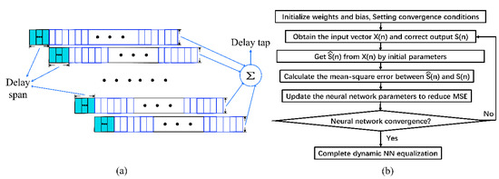
Figure 2.
(a) The schematic diagram of delay and (b) the algorithm flowchart of the proposed NN equalizer.
In particular, the random data are applied into all the measurements to avoid the overestimation with the use of a PRBS. The cycle length of the random data is 10,000. There are 16 neural nodes in each layer. The network is trained with back-propagation and gradient descent with Adam optimization. In this work, the neural network can get the relationship between the adjacent symbols and get the correct data by extending the dimension of the data through delay processing. Compared with the traditional linear equalizer, besides the basic equalization ability, the hidden layer of the network enhances the learning ability, and the activation function enhances the expression ability, so it has the potential to obtain a better equalization effect especially in the multi-mode, non-linear, and other complex transmission environments.
The experimental setup for evaluating the performance of the proposed equalization scheme is illustrated in Figure 3. At the transmitter side, the random data are generated and mapped into the PAM-4 format by Matlab, and then they are sent to the Keysight M8196A arbitrary waveform generator (AWG) for electric signal generation. The sampling rate of the AWG was 92 GS/s and the corresponding bandwidth was 30 GHz. The eye diagram of the 100 Gb/s electrical PAM-4 signal emitting from the AWG (point a) without optoelectronic and electro-optical devices is also shown in Figure 3a, in which case the eyes are clearly visible. Since the maximum output voltage of the AWG was only 500 mV, a broadband electric amplifier with 55 GHz bandwidth was connected to the AWG to amplify the voltage. An 850 nm Fabry Perot (FP) laser was employed and followed by a 25 G 850 nm Mach–Zehnder modulator (MZM), which was provided by Bonphot (850 MODBOX). A polarization controller was not included in our experimental setup because polarization while maintaining optical fiber was used for connecting the laser source and the MZM. The insertion loss of the MZM was 4.5 dB, the optical output power of the laser source was 11 dBm, and the corresponding optical power injected into optical backplane was around 6.5 dBm. After 40 cm optical backplane transmission, the RoP was adjusted by a variable optical attenuator (VOA).
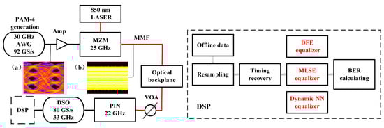
Figure 3.
Experimental setup for evaluating the proposed scheme.
At the receiver side, the optical signal was detected by a 22 G positive intrinsic-negative (PIN) detector. The detected signal was then sampled by an 80 GS/s real-time digital storage oscilloscope (DSO) with a 33 GHz bandwidth to obtain the data for offline analysis. The eye diagram of the 100 Gb/s electrical PAM-4 signal output from PIN after the 40 cm optical backplane (point b) is also depicted in Figure 3, which shows that the quality of the eye diagram was very poor.
An offline digital signal processing (DSP) is executed by the Matlab program, and this procedure is shown in Figure 3. The sampled data from the DSO were first resampled to make sure that there were integer symbols in the sampling period. Then, the optimal sampling point was obtained based on the absolute-value timing symbol recovery algorithm. After the equalization, the BER was then calculated for the evaluation of the system performance. Two types of common equalization schemes including DFE and MLSE were considered for comparative analysis.
The optical backplane employed in the present experiment was in-house fabricated, with its specific parameters shown in reference [26]. As shown in Figure 4, a total of 10 rectangular optical waveguides (ROWs) were embedded in the substrate of the optical backplane. Two ends of the waveguide were coupled to the optical multi-mode 1 (OM1) MMF from the substrate by using dedicated connectors. The cross-sectional view of one of the ROWs is also provided in Figure 4, where the refractive index of the core is shown to have been 1.4662, slightly higher than that of the cladding (1.45). It could restrict the transmission of light waves in the core layer in the form of a guided wave pattern along the optical waveguide. The width of core is 50 μm, and the height of core is 50 μm. According to the mode-coupling theory, the phase velocity in the ROW as well changes with the frequency, which is similar to circular waveguides such as the MMF.
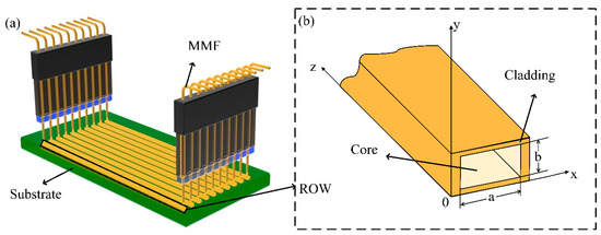
Figure 4.
(a) The schematic diagram on the spatial structure of the optical backplane (b) the cross-sectional view of the rectangular optical waveguide (ROW).
The insertion loss characteristics for each lane of the optical backplane were measured with the 850 nm laser source and the optical power meter, with results given in Figure 5. Notably, the dedicated connector between the optical backplane and the OM1 MMF pigtail was included in the mentioned measurement. In order to get relatively reasonable results, channel 5 was selected during the measurements.
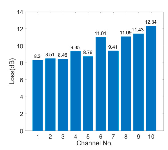
Figure 5.
The insertion loss characteristics for each lane of the optical backplane.
3. Experimental Results and Discussions
We firstly measured the transmission characteristics of the employed optical backplane. The frequency response of the end-to-end system to the optical transmission path was measured under configurations for both with and without optical backplane as depicted in Figure 6. A N5227B Keysight project network analysis (PNA) network analyzer with a 67 GHz bandwidth was employed in the mentioned measurements. The measured path was between the MZM input port and the PIN output port. The frequency for the 3 dB bandwidth of the transmission system with and without an optical backplane was 18 and 18.15 GHz, respectively. The nominal bandwidth of employed devices in our experiments was specific for the non-return-to-zero (NRZ) modulation signals, which means that the analog bandwidth basically agreed with above mentioned results. The result indicates that the employment of the optical backplane had a slight impact on frequency fading. Due to the short length of the backplane, the dispersion was not the dominant impairment in the above-mentioned system.
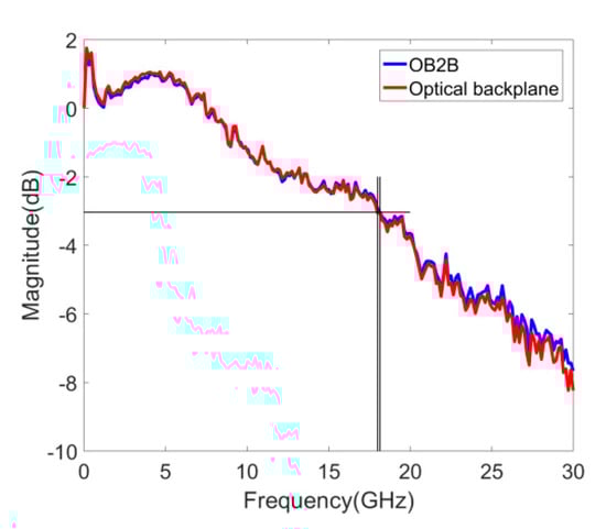
Figure 6.
The measured system’s frequency response to the optical transmission path.
A detailed investigation into the performance of proposed scheme was performed. To set up a reference baseline for the employed equalization methods, optical back-to-back (OB2B) transmission experiments of the 80 Gb/s PAM-4 signal were firstly performed with the direct decision, and the DFE, MLSE and proposed NN equalization algorithms were employed. During the measurements, the RoP changed from −2.5 to −12.5 dBm with a 1 dB decrement. The BER curves with the mentioned direct decision and DFE equalization algorithms are shown in Figure 7. For both cases, the BER could not be lower than the adopted 7% HD-FEC limit for all measured RoP values. In the DFE case, the training length was 1000, and the tap is 3. As a linear equalizer, DFE got the right optimal tap coefficient through the training sequence. DFE is an essentially linear mapping, which means that it lacks the ability to compensate for the impairment induced by a constrained bandwidth. The BER performance deteriorated as the RoP decreased from −8.5 to −12.5 dBm. However, when the RoP was above −8 dBm and kept increasing, the BER did not decrease, indicating that the impairment of the signal at this bit rate exceeded the compensation limit of DFE.
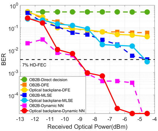
Figure 7.
The curves of the bit error rate (BER) versus the received optical power (RoP) of transmission with decision feedback equalization (DFE), maximum likelihood sequence estimation (MLSE) and the NN equalization scheme for 80 Gb/s.
The MLSE case considered all the sequences that may be formed after convolution of effective transmission sequence and channel impulse response, and a sequence with minimum distance from the received signal was found. Here, the memory length used was 4. As displayed in Figure 7, the BER decreased with the increase of the RoP and was even lower than the HD-FEC when the RoP was higher than −4.5 dBm. In addition, for the MLSE case, the BER curve after transmission through the optical backplane was basically the same as the OB2B curve, thus confirming the transmission features as mentioned in Figure 7. In the following measurements, MLSE was used as the reference algorithm for comparison. It is worth mentioning that this paper only discusses the performance of the equalization algorithm at the adopted forward error correction (FEC) threshold due to the fact that the implementation of the FEC can be achieved by special hardware and software.
As shown in the performance of the proposed NN algorithm plotted in Figure 7, the BER also decreased with the increase of the RoP at the transmission rate of 80 Gb/s. The proposed method achieved about 5 dB power penalty improvement compared with MLSE at the FEC threshold. The BER with the optical backplane was similar to the OB2B curve, which was similar to the MLSE case. During the experimental measurements, we found that for both the optical backplane case and the B2B case, the developed trend of the BER curves for mentioned scheme were similar, which is also consistent with Figure 6. It is worth mentioning that, for the NN equalization scheme case, error free transmission could be achieved for the B2B case at an RoP higher than −5.5 dBm. Moreover, for the lower BER region, the greater the BER fluctuation was caused by the same number of error bits. For the bandwidth-limited system considered here, DFE could not meet the demand, and the introduction of the NN equalization algorithm became necessary. Compared to DFE and MLSE, the NN outperformed due its powerful modeling capabilities, which owed to the architecture of the multi-layer neural network and nonlinear activation function in each neuron. We also noticed that for a few points, increasing the RoP resulted in an slightly increase in the BER, and such BER fluctuation was mainly because the training phase of the neural network had a gradient descent direction, and the training result fluctuated to a certain extent. However, because the neural network obviously improved the transmission performance, this phenomenon did not affect the significance, even under such fluctuation; detailed investigations around it will be conducted in the future works.
During the measurements, the delay spans and taps exhibited an impact on the performance of the proposed algorithm. Thus, the impacts of the above factors were further studied, with the results shown in Figure 8. We first fixed the span at 16 and then changed the size of the tap. The number was determined by using the data of 80 Gb/s when the RoP is −10.5 dBm. As shown in Figure 8a, as the number of delay taps increased, the equalization performance improved until a point of a BER floor region where a further increase in the complexity of the equalizer was unnecessary. In addition, the performance of the system under different span and tap combinations was also measured, as shown in Figure 8b. The BER performance remained basically unchanged when the number of delay spans was over 1. The same process was repeated, and similar phenomena were obtained when the number of taps was 8, 12 and 16. Thus, the NN equalization scheme was performed under 1 delay span and 16 taps in the present work.
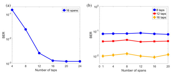
Figure 8.
The BER performance under (a) a different number of taps and (b) a different number of spans.
It is found in Figure 9 that for MLSE and the proposed NN method, the BER tended to further decrease with the further improvement of the RoP. However, due to experimental system limitations, the RoP could not be further increased. Hence, we studied the performance limits of the proposed algorithm by increasing the bit rate. The system performance at 90, 100, 120, and 140 Gb/s with an optical backplane was investigated, with the results given in Figure 9. Due to the similar BER performance of B2B and with the optical backplane case, BER curves with only the optical backplane are plotted in Figure 9 in order to make a clear comparison. Considering that 80 Gb/s was already beyond the capability of the DFE, only MLSE was applied in the following measurements for the comparison. The trend of the curves was similar to that of 80 Gb/s. When the bit rate was over 90 Gb/s, MLSE could meet the FEC limit anymore in the range of the experimental RoP, while the proposed NN case still displayed obvious potential. For the bit rate of 100 Gb/s, the proposed method achieved the adopted HD-FEC requirement at an RoP of around −8 dBm.
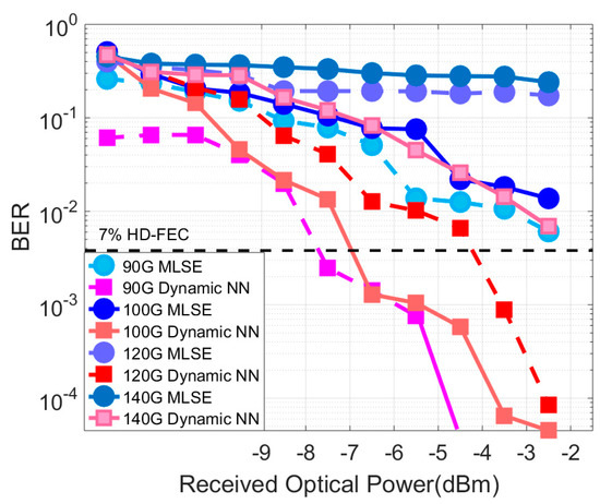
Figure 9.
The curves of the BER versus the RoP from 90 to 140 Gb/s with an optical backplane.
For the bit rate 120 Gb/s, as shown in Figure 9, the BER performance of the proposed scheme could be lower than the FEC limit at the RoP of −4 dBm. When the rate increased to 140 G, the NN algorithm could not make the BER lower than the FEC threshold, nor could it make the BER slightly higher than the FEC threshold at −2.5 dBm. The experimental results showed that under the above bandwidth-constrained transmission conditions, the performance of the NN algorithm was better than that of MLSE, especially for the bit rate over 90 Gb/s.
In summary, we sorted out the data and plotted the BER as a function of the bit rate for the RoP in Figure 10 at a configuration such that the optical backplane was connected to the optical link. Figure 10a is for the MLSE case and Figure 10b is for the NN equalization case. Both the 7% HD-FEC and 20% soft-decision forward error correction (SD-FEC) limits are depicted in the measurement curves. From Figure 10a, it can be seen that the BER was below the 7% HD-FEC at 80 Gb/s only when the RoP was higher than −4.5 dBm. If a 20% SD-FEC is used, when the RoP is higher than −4.5 dBm, 100 Gb/s transmission could be achieved, which also means that the complexity of the decoding calculation was increased. As shown in Figure 10b, when the RoP was higher than −6.5 dBm, 100 Gb/s transmission could be achieved under the 7% HD-FEC. When the RoP was higher than −4.5 dBm, 140 Gb/s could be transmitted under the 20% SD-FEC. The gross maximum achievable rate using MLSE and NN equalization under different RoPs is presented in Table 1 and Table 2 for the 7% HD-FEC case and the 20% SD-FEC case, respectively. This provides an essential reference for future system design in different scenarios.
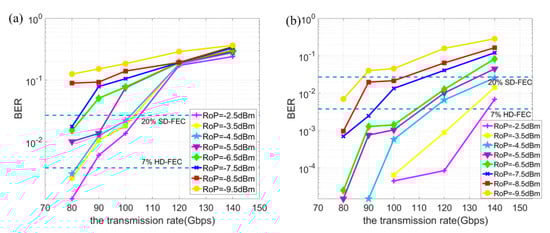
Figure 10.
The curves of the BER versus transmission rate for (a) the MLSE case and (b) the NN equalization case when the RoP ranged from −9.5 to −2.5 dBm (with an optical backplane).

Table 1.
The measured gross maximum data rate (Gb/s) at the 7% hard-decision forward error correction (HD-FEC) limit.
Table 2.
The measured gross maximum data rate (Gb/s) at the 20% SD-FEC limit.
Furthermore, the complexity of the adopted MLSE and neural networks are compared in in Table 3. The number of multipliers was used to represent the complexity of the algorithm. The method for calculating the complexity of MLSE was the same as that in [30], and the method for the NN in [31] was adopted here. For an ANN, denotes the number of completed epochs required for training; , , and are the number of neurons in the input, first hidden, second hidden, and output layers, respectively; for MLSE, M and L represent the number of M-ary modulations and memory lengths of MLSE, respectively. By calculation, the number of multipliers of MLSE in this paper was more than that of the NN. It is also worth mentioning that during our experimental measurements, we found that the use of a single hidden layer and the setting of the hidden node as 16 allowed for the best performance. However, when we further increased the number of layers and nodes, the complexity increased, but the performance was not significantly improved. For the current system configuration, a three-layer fully connected neural network can be considered as an optimal choice between system performance and algorithm complexity.
Table 3.
The complexity comparison between MLSE and the NN.
4. Conclusions
An improved neural network-based equalization method was proposed and experimentally demonstrated. The up-to-137 Gb/s transmission of PAM-4 signals with 25 G class 850 nm optical devices was achieved over an in-house fabricated 40 cm optical backplane. An in-depth investigation was conducted regarding the impact of delayed taps and spans on equalization performance. The performance comparison of the proposed method with the traditional MLSE and DFE was also undertaken. Furthermore, the specific BER performances for varied maximum achievable bit rates under different RoPs that applied MLSE and the proposed method were also analyzed. This provides an important potential solution to realize the future data centers.
Author Contributions
Conceptualization, Q.Z. and H.Z.; Data curation, Q.Z., Y.J., C.D., S.D., Z.W., Y.L., Y.S., J.C. and J.Z.; Formal analysis, Q.Z., Y.J., H.Z., S.D., Z.W., Y.L. and Y.S.; Investigation, Q.Z., Y.J., J.Z. and M.W.; Methodology, Q.Z., Y.J., C.D., S.D., Z.W., Y.L., Y.S. and J.C.; Project administration, H.Z., S.D. and Z.W.; Resources, Y.L., Y.S., J.C. and J.Z.; Software, H.Z., Z.W. and Y.L.; Supervision, J.C., J.Z. and M.W.; Visualization, C.D. and S.D.; Writing—review & editing, C.D., Y.W., T.W. and M.W.
Funding
This research was funded by National Natural Science Foundation of China (Project No. 61601279, 61420106011, 61601277, 61635006); Shanghai Science and Technology Development Funds (Project No. 17010500400, 16511104100).
Conflicts of Interest
The authors declare no conflict of interest.
References
- DeCusatis, C. Optical Interconnect Networks for Data Communications. J. Light. Technol. 2014, 32, 544–552. [Google Scholar] [CrossRef]
- Tan, M.; Rosenberg, P.; Panotopoulos, G.; McLaren, M.; Sorin, W.; Mathai, S.; Kiyama, L.; Straznicky, J.; Warren, D. OPTOPUS: Optical backplane for data center switches. In Proceedings of the Optical Fiber Communication Conference, San Francisco, CA, USA, 9 March 2014; Optical Society of America: Washington, DC, USA, 2014; p. M3E-3. [Google Scholar]
- Boletti, A.; Giacomuzzi, D.; Parladori, G.; Boffi, P.; Ferrario, M.; Martinelli, M. Performance comparison between electrical copper-based and optical fiber-based backplanes. Opt. Express 2013, 21, 19202–19208. [Google Scholar] [CrossRef] [PubMed]
- Driving The Ethernet Roadmap At 100X Speeds. Available online: http://www.ethernetalliance.org/roadmap/ (accessed on 31 March 2015).
- Immonen, M.; Wu, J.; Yan, H.J.; Zhu, L.X.; Chen, P.; Rapala-Virtanen, T. Electro-optical backplane demonstrator with multimode polymer waveguides for board-to-board interconnects. In Proceedings of the 5th Electronics System-integration Technology Conference (ESTC), Helsinki, Finland, 16 September 2014; pp. 1–6. [Google Scholar]
- Krishnamoorthy, A.V.; Thacker, H.D.; Torudbakken, O.; Müller, S.; Srinivasan, A.; Decker, P.J.; Opheim, H.; Cunningham, J.E.; Shubin, I.; Zheng, X.; et al. From chip to cloud: Optical interconnects in engineered systems. J. Light. Technol. 2017, 35, 3103–3115. [Google Scholar] [CrossRef]
- Brusberg, L.; Whalley, S.; Pitwon, R.C.; Faridi, F.R.; Schröder, H. Large Optical Backplane with Embedded Graded-Index Glass Waveguides and Fiber-Flex Termination. J. Light. Technol. 2016, 34, 2540–2551. [Google Scholar] [CrossRef]
- Zhao, C.; Chen, R.T. Hybrid bidirectional optical backplane with multiple bus lines. The International Society for Optics and Photonics. Microelectron. Packag. Laser Process. 1997, 3184, 102–110. [Google Scholar]
- Deng, C.; Wang, T.; Chen, J.; Mou, C.; Zhang, X.; Yan, X.; Pang, F. Roughness estimation of multimode rectangular optical waveguide based on the scattering loss difference between SMFW and MMFW structures. IEEE Photonics J. 2017, 9, 1–13. [Google Scholar] [CrossRef]
- Zhou, H.; Li, Y.; Liu, Y.; Yue, L.; Gao, C.; Li, W.; Qiu, J.; Guo, H.; Hong, X.; Zuo, Y.; et al. Recent Advances in Equalization Technologies for Short-Reach Optical Links Based on PAM4 Modulation: A Review. Appl. Sci. 2019, 9, 2342. [Google Scholar] [CrossRef]
- Reza, A.G.; Rhee, J.K.K. Nonlinear equalizer based on neural networks for PAM-4 signal transmission using DML. IEEE Photonics Technol. Lett. 2018, 30, 1416–1419. [Google Scholar] [CrossRef]
- Reza, A.G.; Rhee, J.K.K. 30-Gb/s PAM-8 Transmission with Directly-Modulated Laser using Machine Learning Equalizer. In Proceedings of the 2018 Asia Communications and Photonics Conference (ACP), Hangzhou, China, 26 October 2018; pp. 1–3. [Google Scholar]
- Kuchta, D.M.; Rylyakov, A.V.; Doany, F.E.; Schow, C.L.; Proesel, J.E.; Baks, C.W.; Westbergh, P.; Gustavsson, J.S.; Larsson, A. A 56.1Gb/s NRZ modulated 850nm VCSEL-based optical link. In Proceedings of the Optical Fiber Communication Conference and Exposition and the National Fiber Optic Engineers Conference, Anaheim, CA, USA, 17–21 March 2013. [Google Scholar]
- Kuchta, D.M.; Rylyakov, A.V.; Schow, C.L.; Proesel, J.E.; Baks, C.; Westbergh, P.; Gustavsson, J.S.; Larsson, A. 64Gb/s Transmission over 57m MMF using an NRZ Modulated 850nm VCSEL. In Proceedings of the Optical Fiber Communications Conference and Exhibition, San Francisco, CA, USA, 9 March 2014; Optical Society of America: Washington, DC, USA, 2014. [Google Scholar]
- Kuchta, D.M.; Rylyakov, A.V.; Doany, F.E.; Schow, C.L.; Proesel, J.E.; Baks, C.W.; Westbergh, P.; Gustavsson, J.S.; Larsson, A. A 71-Gb/s NRZ Modulated 850-nm VCSEL-Based Optical Link. IEEE Photonics Technol. Lett. 2015, 27, 577–580. [Google Scholar] [CrossRef]
- Castro, J.M.; Pimpinella, R.; Kose, B.; Huang, P.; Lane, B.; Szczerba, K.; Westbergh, P.; Lengyel, T.; Gustavsson, J.S.; Larsson, A.; et al. Investigation of 60 Gb/s 4-PAM Using an 850 nm VCSEL and Multimode Fiber. J. Light. Technol. 2016, 34, 3825–3836. [Google Scholar] [CrossRef]
- Lengyel, T.; Szczerba, K.; Westbergh, P.; Karlsson, M.; Larsson, A.; Andrekson, P.A. Sensitivity Improvements in an 850-nm VCSEL-Based Link Using a Two-Tap Pre-Emphasis Electronic Filter. J. Light. Technol. 2017, 35, 1633–1639. [Google Scholar] [CrossRef]
- Castro, J.M.; Pimpinella, R.; Kose, B.; Huang, Y.; Lane, B.; Szczerba, K.; Westbergh, P.; Lengyel, T.; Gustavsson, J.S.; Larsson, A.; et al. 50 Gb/s 4-PAM over 200 m of high bandwidth MMF using a 850 nm VCSEL. In Proceedings of the Optical Fiber Communication Conference, Los Angeles, CA, USA, 22 March 2015; Optical Society of America: Washington, DC, USA, 2014; p. W1D-1. [Google Scholar]
- Karinou, F.; Stojanovic, N.; Prodaniuc, C.; Agustin, M.; Kropp, J.; Ledentsov, N.N. Solutions for 100/400-Gb/s ethernet systems based on multimode photonic technologies. J. Light. Technol. 2017, 35, 3214–3222. [Google Scholar] [CrossRef]
- Kottke, C.; Caspar, C.; Jungnickel, V.; Freund, R.; Agustin, M.; Kropp, J.R.; Ledentsov, N.N. High-speed DMT and VCSEL-based MMF transmission using pre-distortion. J. Light. Technol. 2018, 36, 168–174. [Google Scholar] [CrossRef]
- Lavrencik, J.; Varughese, S.; Gustavsson, J.S.; Haglund, E.; Larsson, A.; Ralph, S.E. Error-free 100Gbps PAM-4 transmission over 100m wideband fiber using 850nm VCSELs. In Proceedings of the 2017 European Conference on Optical Communication (ECOC), Gothenburg, Sweden, 17 September 2017; pp. 1–3. [Google Scholar]
- Lavrencik, J.; Thomas, V.A.; Varughese, S.; Ralph, S.E. Dsp-enabled 100 gb/s pam-4 vcsel mmf links. J. Light. Technol. 2017, 35, 3189–3196. [Google Scholar] [CrossRef]
- Maghrabi, M.M.T.; Kumar, S.; Bakr, M.H. Nonlinear neural network equalizer for metro optical fiber communication systems. In Proceedings of the 2018 International Applied Computational Electromagnetics Society Symposium (ACES), Beijing, China, 25 March 2018; pp. 1–2. [Google Scholar]
- Chuang, C.Y.; Wei, C.C.; Lin, T.C.; Chi, K.L.; Liu, L.C.; Shi, J.W.; Chen, Y.K.; Chen, J. Employing deep neural network for high speed 4-PAM optical interconnect. In Proceedings of the 2017 European Conference on Optical Communication (ECOC), Gothenburg, Sweden, 17 September 2017; pp. 1–3. [Google Scholar]
- Zhou, Q.; Yang, C.; Liang, A.; Zheng, X.; Chen, Z. Low computationally complex recurrent neural network for high speed optical fiber transmission. Opt. Commun. 2019, 441, 121–126. [Google Scholar] [CrossRef]
- Wan, Z.; Li, J.; Shu, L.; Luo, M.; Li, X.; Fu, S.; Xu, K. Nonlinear equalization based on pruned artificial neural networks for 112-Gb/s SSB-PAM4 transmission over 80-km SSMF. Opt. Express 2018, 26, 10631–10642. [Google Scholar] [CrossRef] [PubMed]
- Giacoumidis, E.; Le, S.T.; Ghanbarisabagh, M.; McCarthy, M.; Aldaya, I.; Mhatli, S.; Jarajreh, M.A.; Haigh, P.A.; Doran, N.J.; Ellis, A.D.; et al. Fiber nonlinearity-induced penalty reduction in CO-OFDM by ANN-based nonlinear equalization. Opt. Lett. 2015, 40, 5113–5116. [Google Scholar] [CrossRef]
- Sidelnikov, O.; Redyuk, A.; Sygletos, S. Nonlinear Equalization in Long Haul Transmission Systems Using Dynamic Multi-Layer Perceptron Networks. In Proceedings of the 2018 European Conference on Optical Communication (ECOC), Rome, Italy, 23 September 2018; pp. 1–3. [Google Scholar]
- Yi, L.; Li, P.; Liao, T.; Hu, W. 100Gb/s/λ IM-DD PON Using 20G-Class Optical Devices by Machine Learning Based Equalization. In Proceedings of the 2018 European Conference on Optical Communication (ECOC), Rome, Italy, 23–27 September 2018; pp. 1–3. [Google Scholar]
- Xu, T.; Li, Z.; Peng, J.; Tan, A.; Song, Y.; Li, Y.; Chen, J.; Wang, M. Decoding of 10-G optics-based 50-Gb/s PAM-4 signal using simplified MLSE. IEEE Photonics J. 2018, 10, 1–8. [Google Scholar] [CrossRef]
- Kyono, T.; Otsuka, Y.; Fukumoto, Y.; Owaki, S.; Nakamura, M. Computational-Complexity Comparison of Artificial Neural Network and Volterra Series Transfer Function for Optical Nonlinearity Compensation with Time-and Frequency-Domain Dispersion Equalization. In Proceedings of the 2018 European Conference on Optical Communication (ECOC), Rome, Italy, 23 September 2018; pp. 1–3. [Google Scholar]
© 2019 by the authors. Licensee MDPI, Basel, Switzerland. This article is an open access article distributed under the terms and conditions of the Creative Commons Attribution (CC BY) license (http://creativecommons.org/licenses/by/4.0/).