Abstract
An effective reduced-order model is presented in this paper for the vibration analysis of a mistuned blade–disc–shaft assembly considering the flexibility of the shaft and the rotordynamic effects. For the sake of accurate modeling and quantitative analysis, three-dimensional (3D) finite element models were employed in obtaining the governing equations of motion with the Coriolis force, centrifugal stiffening, and spin softening effects taken into account. Then, an efficient model order reduction technique based on the coordinate projection by normal modes of tuned assembly and cyclic symmetry analysis was developed for mistuned blade–disc–shaft assembly. The criterion of whether one matrix could be incorporated in cyclic symmetry analysis is presented. During the modeling, the mistuning in blade and disc was taken into account and dealt with independently. In mistuning projection, the blade and disc parts were both projected onto their tuned counterparts of the sector model, where the boundary conditions were set to be fixed and free, respectively. Finally, an example of a blade–disc–shaft assembly was employed to validate the effectiveness of the presented method in free and forced vibration analysis.
1. Introduction
Blade–disc–shaft assemblies are the key components of engines and compressors and take an important position in the design of these machines [1]. As the basis for design, developing accurate dynamic models for such assemblies and gaining deep insight into their vibration characteristics are of great significance. For this reason, the vibration issues of blades and rotor systems attracted enormous attention from researchers and engineers, and a huge number of investigations were published in the past few decades [1,2,3,4]. Nevertheless, most of the available investigations concentrated either on the vibration of the blade and disc by neglecting the flexibility of the shaft or on the dynamics of rotor systems by assuming the blade and disc to be rigid and tuned.
Some researchers considered the mutual interactions between bladed discs and shafts and developed several dynamic models for blade–disc–shaft assemblies. Crawley et al. [5] presented a simplified analytical model for rotating a flexible blade-rigid disc-flexible cantilevered shaft system. Okabe et al. [6] addressed an equivalent modeling technique for a blade–shaft system by dividing the system into a shaft plus additional equivalent mass-spring models of blades. Zhang et al. [7] presented a method for dynamic analysis of flexible blade–disc–shaft systems by means of the finite element method and a modal synthesis approach. Huang et al. [8] developed an analytical approach for the coupled shaft torsion and blade bending vibration analysis using the weighted residuals method. Chun et al. [9] proposed an analytical substructure synthesis method for analyzing the coupled free vibrations between shaft and blades. A1-Bedoor [10,11] presented efficient models for coupled shaft-torsional and blade-bending vibration analysis using Lagrange’s equation and the assumed modes method. Ma et al. [12] developed a dynamic model for rotor–blade systems by representing blades as Timoshenko beams and shafts as multiple lumped mass points connected by massless springs. She et al. [13] developed an analytical model for the coupling vibration analysis of a blade–disc–shaft system. In these investigations, the mistuning in blades and discs, which is an inevitable issue due to manufacturing tolerances, material deviations, and in-service wear, tended to be neglected. Regarding this issue, some researchers took mistuning into account. Khader et al. [14] presented a simple analytical model for non-rotating flexible blade-rigid disc-flexible shaft assemblies by representing blade mistuning as frequency deviations. Kim [15] developed a simplistic model for describing the in-plain whirling behavior of a mistuned bladed rotor using complex coordinate transformation and modulation. Li et al. [16] established a dynamic model for a shaft–disc–blade system considering the mistuning in blade length and stagger angle. These investigations provided effective ways for the modeling of blade–disc–shaft assemblies. Nevertheless, the models developed in these investigations were mainly analytical or lumped with, more or less, some simplifications and assumptions. Although such models have the advantages of ease of use, they have limitations in modeling and analysis of complex rotor assemblies, such as those of engines and compressors in practical industrial application.
Three-dimensional (3D) finite element models could overcome these limitations by discretizing the complex assemblies as solid elements, where the detailed geometry can be accurately captured, and the flexibility of all components can be taken into account. Such models were widely employed in the modeling and analysis of bladed discs [17,18,19,20] and complex rotor systems [21,22,23,24]. Nevertheless, the huge number of degrees of freedom (DOFs) in 3D finite element models hinders the computational efficiency in analysis, especially for systems containing random factors, such as mistuning. Hence, a number of model order reduction techniques were developed, including the generalized component mode synthesis methods [25,26,27] and some other effective methods for specific structures, such as the subset of nominal modes (SNM) [28], the fundamental mistuning model (FMM) [29], and the component mode mistuning method (CMM) [30] for mistuned bladed discs. The substructure-based methods are more general approaches for reduced-order modeling. Nevertheless, they are often not that efficient in analyzing mistuned blade discs, as a large number of interface DOFs may be retained, resulting in the model not being concise enough. SNM, FMM, and CMM are more efficient methods, as they were proposed with respect to mistuned bladed discs. In these investigations, however, the shafts were commonly assumed to be rigid and their flexibilities tended to be neglected. For the analysis of mistuned a blade–disc–shaft assembly, the flexibility of the shaft should not be neglected, as it may lead to non-negligible coupling vibration between the shaft and bladed disc. Therefore, an effective model order reduction technique for a mistuned blade–disc–shaft assembly remains to be developed.
In this paper, a reduced-order model for the vibration analysis of mistuned blade–disc–shaft assemblies is presented, where the rotordynamic effects are all taken into account. Firstly, 3D finite element models of blade–disc–shaft assemblies are employed to obtain the governing equations of motion. Then, an efficient model order reduction technique based on the coordinate projection by normal modes of tuned assembly and cyclic symmetry analysis is developed. During the model order reduction, the mistuning in blade and disc is taken into account and dealt with independently. Finally, the effectiveness of the presented method is validated by an example of a blade–disc–shaft assembly. This paper is organized as follows: in Section 2, the governing equations of motion are presented. Section 3 addresses the formulations of model order reduction. Section 4 contains the validation of the presented method. Conclusions are given in Section 5.
2. Equations of Motion
Practical blade–disc–shaft assemblies tend to possess complex geometries, which are hardly modeled by lumped parameter models without several simplifications. Three-dimensional finite element models could accurately describe complex structures without simplifications. As bladed discs tend to be axially symmetric, their governing equations contain periodically time-variant terms if analyzed in inertial frames of reference. Therefore, the rotating frames are employed in this paper. For a 3D finite element model of a mistuned blade–disc–shaft assembly, its governing equation of motion at a constant rotating angular velocity has the following general form:
where , , and are the mass, damping, and elastic stiffness matrices of the assembly, , , and represent the speed-dependent Coriolis, centrifugal stiffening, and spin softening matrices, respectively, denotes the additional stiffness matrix due to mistuning, is the vector of response, and represents the vector of external forces. As the 3D finite element models are employed, the above matrices are obtained via linear assumption. In this paper, the external forces acting on the blades are assumed to be traveling wave excitations, where the forces on the ith blade can be expressed as
where denotes the forcing amplitude vector, represents the angular frequency of excitation, and , where C is the engine order (EO) of excitation, and is the interblade phase angle defined as , where , and N is the number of blades.
3. Reduced-Order Modeling
3.1. Model Order Reduction via Cyclic Symmetry Analysis
Model order reduction techniques are often employed, combined with finite element models, to significantly reduce the computational requirements during analysis. It is much more urgent for mistuned bladed discs, as mistuning is highly random and thousands of mistuning patterns are often needed to study the statistical vibration characteristics. In this paper, the ideas presented in References [28,29,30] are employed and further developed for blade–disc–shaft assemblies. From a general perspective of view, these methods belong to the mode superposition method, whereas the modes used are those of a tuned bladed disc rather than a certain mistuned case. According to these approaches, the normal modes of the tuned blade–disc–shaft assemblies are used as the basis for projecting the mistuned physical model into a modal domain, which can be represented as
where denotes the mode matrix of the tuned assembly in static condition, where the matrices due to rotation are not included during eigenvalue analysis, and represents the modal coordinate vector. The effectiveness of this coordinate transformation for mistuned blade–disc–shaft assemblies is validated in the next section.
In the vibration analysis of bladed discs, the cyclic symmetry properties are often employed to reduce the computation requirements [31,32]. A tuned blade–disc–shaft assembly is also cyclically symmetric if the shaft is axially symmetric. In the analysis of a rotating blade–disc–shaft assembly, the rotordynamic effects should not be neglected. However, few relative investigations considered these effects. As the rotordynamic matrices are all speed-dependent, the Coriolis matrix is skew-symmetric, and the centrifugal stiffening matrix depends on the stress distributions due to centrifugal forces, whether these matrices can be included in cyclic symmetry analysis should be rigorously verified. It can be proven that one matrix could be incorporated in cyclic symmetry analysis if such a matrix of the sector model has the following relationship with that of its adjacent sector.
where and denote the matrices of sth and (s + 1)th sectors, respectively, and represents a rotation transformation matrix in term of the sector angle.
where denotes an identity matrix of dimensions , where is the number of nodes in a sector model, the symbol denotes the Kronecker product, and is an elementary matrix. Taking the rotation axial along the z-axis as an example, can be expressed as
Detailed proof of this proposition, for brevity, is presented in Appendix A. According to the explanation in Appendix A, the Coriolis, centrifugal stiffening, and spin softening matrices can all be incorporated in cyclic symmetry analysis. In this circumstance, the mode matrix represented in terms of cyclically symmetric modes can be used as the projecting basis during model order reduction. Then, can be explicitly expressed as
where denotes the complex Fourier matrix with for , denotes an identity matrix, is the mode matrix of hth nodal diameter (ND), and denotes a pseudo-block diagonal matrix with in its diagonal. Then, the governing equation in Equation (1) can be reduced by using the coordinate transformation in Equation (3) as
where
where
where the subscripts of “1”, “2” and “3” in the above matrices represent the terms in the corresponding block-circulated matrices in Equation (A10) shown in Appendix A.
The reduced-order mistuning matrix is also generated via the coordinate transformation in Equation (3), giving
In most available investigations, only the mistuning in blades was taken into account. This may partly have been because the blade tends to be more flexible and less structurally coupled than the disc. Actually, mistuning in discs is also inevitable due to manufacturing tolerances and deteriorations during operation. The mistuning in discs may not play that significant a role as blades in the vibration of bladed discs. Nevertheless, it may be non-negligible for blade–disc–shaft assemblies, as the flexibilities in the shaft may lead to significant coupling motions between the shaft and disc. Therefore, the mistuning in blades and discs is considered and dealt with independently in this paper. Then, can be further expanded, without loss in accuracy, into blade and disc parts as
where and denote the mode matrices corresponding to the blade and the disc parts, respectively, and and represent the corresponding mistuning matrices of the two parts. Despite the simple expressions, and are difficult to determine, as the mistuning matrices and of a realistic bladed disc are highly random and difficult to measure. For this reason, frequency mistuning models were more often employed in available investigations for mistuning quantization. In this paper, such a model is also used. Detailed deductions on obtaining the reduced-order mistuning matrices and are presented in the sections below.
3.2. Parametric Projection of Blade Mistuning
The mistuning projection method proposed by Lim et al. [30] is employed in this section to include blade mistuning in the reduced-order model. The core idea of this method is to project the mistuning matrix onto the normal modes of a tuned blade cantilevered at its root. The main procedures of this method are briefly reviewed herein. Firstly, the blade part mode is represented by cyclically symmetric modes as shown in Equation (7).
where denotes the blade part of , and is an identity matrix of dimensions , where denotes the number of DOFs in a sector model of blade.
Then, the blade part’s cyclically symmetric modes are represented by the normal modes of the tuned blade cantilevered at its root.
where is the normal mode matrix of the tuned cantilevered blade, and denotes the participation factor. By the above transformation, , where . As the blades are not directly coupled, has a block-diagonal form as . Then, the blade part’s reduced-order mistuning matrices can be expressed as
where . As tends not to be diagonal, it is often approximately processed in frequency mistuning models by keeping only the diagonal elements, which can be represented as
where M is the number of retained modes of the tuned cantilevered blade, represents the mth eigenvalue of the tuned cantilevered blade, and denotes the deviation ratio, which is often set to be a random parameter during analysis.
3.3. Parametric Projection of Disc Mistuning
Unlike the projection of blade mistuning, the coordinates between adjacent sectors of the disc are directly coupled, and the disc mistuning matrix cannot be expressed in block-diagonal form. Therefore, the mistuning projection method in the previous section cannot be directly employed. Nevertheless, the idea of representing the overall modes by normal modes of a relatively simple component and projecting the mistuning matrix onto these normal modes can be utilized. Of course, some modifications to the formulations are needed to account for the coupling issue of the disc model.
Firstly, the disc part mode is represented by cyclically symmetric modes.
where denotes the disc part of , and is an identity matrix of dimensions , where is the number of DOFs in a sector model of the disc with the left cyclic symmetry surface eliminated.
As mentioned above, the mistuning matrices of adjacent sectors of the disc are crossed and coupled. Proper processes are needed to make the matrix block-diagonal. It can be found that adjacent sector models can be made independent in form by coordinate expansion, where the original and expanded coordinates with respect to the disc model are expressed as
where denotes the original coordinate vector with respect to , is the expanded coordinate, and the subscript “R”, “L” and “I” denote the right and left cyclic boundary DOFs and internal DOFs, respectively. It can also be proven that the disc mistuning matrix can be obtained using an expanded block-diagonal matrix , with
where denotes the expanded modes with respect to . Detailed deductions on this proposition are presented, for brevity, in Appendix B. Similar to the expression of in Equation (17), the expanded modes with respect to can also be expressed by cyclically symmetric modes.
where denotes the expanded cyclic modes of , and
where is a matrix dependent on ; for hND modes,
where denotes a rotation transformation matrix, and , where is an identity matrix of dimensions , and is the number of nodes on cyclic symmetry interface.
Then, similar to that shown in Equation (14), the expanded cyclic modes are represented by the normal modes of the disc component.
where denotes the normal mode matrix of a tuned sector model of the disc with the left and right interfaces, as well as the adjacent interface between the disc and shaft, being set to be free, and denotes the participation factor. Herein, the free constraint is employed on the disc–shaft adjacent interface instead of a fixed one, because the latter one may not accurately describe the 1ND coupling modes between shaft and disc, leading to non-negligible errors in forced responses. The employment of free modes avoids such issues and presents satisfactory results in both frequencies and forced responses.
By substituting Equation (22) into the expression of and neglecting the non-diagonal terms, the disc part’s reduced-order mistuning matrices can be expressed as
where , W is the number of retained modes of the disc component, is the deviation ratio, and denotes the wth eigenvalue of the tuned disc component.
On this basis, the free and forced vibration of tuned and mistuned blade–disc–shaft assemblies can be analyzed by using the governing equation of motion in Equation (8) and the coordinate transformation in Equation (3). As the mistuning in blade and disc is taken into account, the effects of blade and disc mistuning on the vibration characteristics of blade–disc–shaft assemblies can be investigated.
4. Validation of Reduced-Order Models
Validation of the developed order reduction method is presented in this section. As the accuracy of the reduced-order model in vibration analysis for practical structures relies on the accuracy of its counterpart full-order model, the effectiveness of the developed method can be verified by comparing the results of the reduced-order model with those of the full order model.
Figure 1 illustrates the finite element model of a blade–disc–shaft assembly, which is used as an example in this section, where the DOFs of the whole model and the sector model are equal to 103,563 and 7179, respectively. The whole model contains 18 sectors. The reduced-order model contains 216 DOFs with 12 modes per ND. During the projection of blade and disc mistuning, the retained modes of the cantilevered blade and free disc are 20 and 50, respectively. The excitation is applied at the tip of the blades with an amplitude of 2 N. The structural damping is assumed to be Rayleigh damping and , where is set to 3 × 10⁻⁶ in the subsequent analysis. The material of the blade and disc is titanium alloy, and that of the shaft is steel, where the properties of these materials are listed in Table 1.
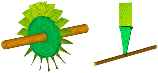
Figure 1.
The finite element model of a blade–disc–shaft assembly and its sector model.

Table 1.
Material properties of the blade, disc, and shaft.
Generally, the mistuning in the blade and disc is random and hard to measure. Herein, a simpler mistuning model, the commonly used proportional mistuning model, is used to validate the developed method. Small random variations in Young’s modulus are introduced as
where and denote the Young’s modulus of the nth sector models of the blade and disc, represents the nominal Young’s modulus, and and are random variables representing the small variations. Specifically, the employed proportional mistuning patterns of the blade and disc in the subsequent analysis are listed in Table 2.

Table 2.
The mistuning parameters of the blade and disc.
Figure 2 illustrates the natural frequencies versus nodal diameters of the tuned blade–disc–shaft assembly in a static condition. Some of the 0ND and 1ND modes are shaft-dominated and not involved in the lines. With this diagram, the excited modes can be easily obtained by comparing the exciting frequency and the natural frequencies.
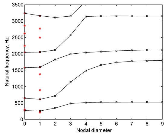
Figure 2.
Natural frequencies versus nodal diameters of the tuned blade–disc–shaft assembly in a static condition.
Figure 3 shows the comparisons of the forced responses of the mistuned blade–disc–shaft assembly using the normal modes of the mistuned case and those of its tuned counterpart. The presented results are the responses of the excitation nodes, which are located at the tip of each blade. In the subsequent analysis, the results of these nodes are also employed. It can be seen in the figures that the results agree very well. The maximum relative error in amplitude is less than 0.1%. Therefore, the normal modes of the tuned blade–disc–shaft assembly can accurately represent the modes of mistuned assembly.
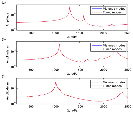
Figure 3.
Comparisons of the forced responses of the excitation nodes of the assembly using the normal modes of the mistuned case and those of its tuned counterpart with excitations of (a) one engine order (1EO), (b) 2EO, and (c) 3EO.
Figure 4 shows the comparisons of the first 100 natural frequencies of the tuned assembly using the full-order model and cyclic symmetric sector model. It can be seen in the figure that the two cases agree well, with the maximum relative error in natural frequency being less than 0.01%. Therefore, cyclic symmetry analysis is also feasible for bladed discs mounted on flexible shafts.
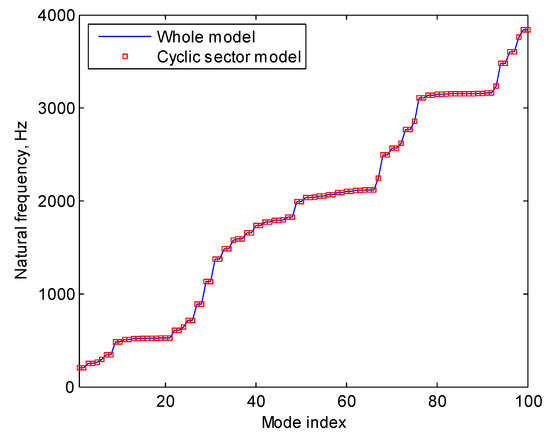
Figure 4.
Comparisons on the first 100 natural frequencies of the tuned blade–disc–shaft assembly using the full-order model and cyclic symmetry sector model.
Figure 5 shows the relative errors in eigenvalues of the reduced-order model at different rotating speeds, where the first 20 are included and the mistuning in the blade and disc is considered. It can be seen in the figure that the relative error grows with rotating speed but within a relatively small range. Although the relative errors increase for higher-order eigenvalues, the overall maximum relative error is still less than 0.1% when the rotating speed is less than 2000 rad/s. Thus, the presented model order reduction technique can give accurate results in eigenvalues for a mistuned blade–disc–shaft assembly in spite of the significant reduction in model order.
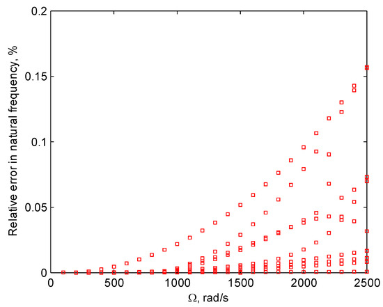
Figure 5.
The relative errors in eigenvalues of the reduced-order model of a mistuned blade–disc–shaft assembly at different rotating speeds.
Figure 6 and Figure 7 illustrate the comparisons of forced responses of the assembly between the full-order model (FOM) and reduced-order model (ROM) with mistuning in the blade and disc, respectively, where the 1EO, 2EO, and 3EO excitations are presented. As can be seen in the figures, for both cases of blade and disc mistuning, the two models give quite similar results in the entire speed range with different EOs of excitations. Thus, it can be concluded that the reduced-order model can give quite accurate results in forced responses compared with those of the full-order model.
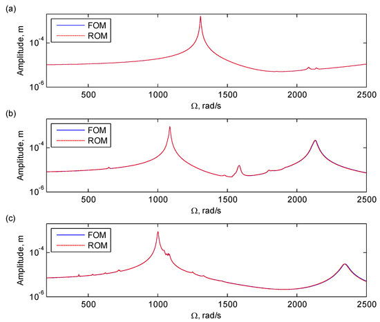
Figure 6.
Comparisons of the forced responses of the excitation nodes of the assembly with blade mistuning between the full-order model and reduced-order model with excitations of (a) 1EO, (b) 2EO, and (c) 3EO. The full- and reduced-order models contain 103,563 and 7179 degrees of freedom (DOFs), respectively.
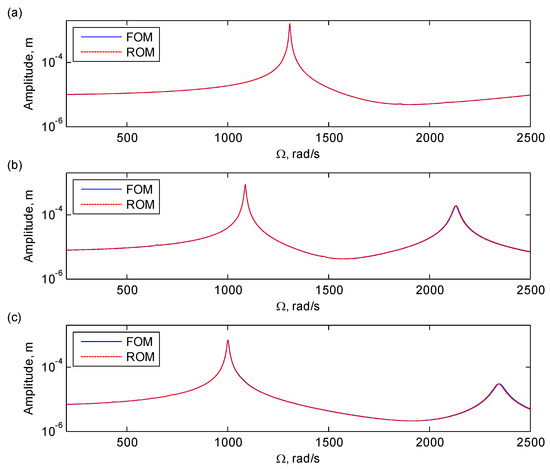
Figure 7.
Comparisons of the forced responses of the excitation nodes of the assembly with disc mistuning between the full-order model and reduced-order model with excitations of (a) 1EO, (b) 2EO, and (c) 3EO. The full- and reduced-order models contain 103,563 and 7179 DOFs, respectively.
In order to illustrate the efficiency of the presented method, the computational time of the reduced-order model in computing natural frequencies and forced responses is compared with that of the full-order model, which is listed in Table 3. The specifications of the employed computer during the analysis were as follows: Intel Core i7-8700 central processing unit (CPU) with 3.20 GHz; size and speed of the cache memory = 32 GB and 2666 MHz, respectively; size of the solid-state drive (SSD) hard disk = 512 GB. The presented values are all the averages of 100 analysis cases. It can be seen that the presented model order reduction technique could significantly increase the computational efficiency.

Table 3.
Comparison on the computational efficiency between full-order model (FOM) and reduced-order model (ROM).
Based on the results presented in this section, the effectiveness and efficiency of the presented method can be validated. With this method, the coupling vibrations between bladed disc and shaft, as well as the effects of the shaft’s flexibility on the vibration of a mistuned bladed disc, can be studied. Nevertheless, these issues are not the focus of this paper and can be addressed in further studies.
5. Conclusions
In this paper, an effective reduced-order model was presented for the vibration analysis of a mistuned blade–disc–shaft assembly. Three-dimensional finite element models, which can provide accurate modeling and quantitative analysis for complex structures, were introduced to obtain the governing equations of motion, where the Coriolis force, centrifugal stiffening, and spin softening effects due to rotation were all taken into account. An efficient model order reduction technique, based on the coordinate projection by normal modes of tuned assembly and cyclic symmetry analysis, was developed for a mistuned blade–disc–shaft assembly. As the basis for employing cyclic symmetry analysis, the criterion of whether one matrix could be incorporated in the analysis, as well as rigorous proof, was given. It was shown that the Coriolis, centrifugal stiffening, and spin softening matrices satisfy this criterion and can be converted into block-circulated forms in cyclically symmetric coordinates. In the presented model order reduction method, the mistuning in the blade and disc was taken into account and dealt with independently to reflect the realistic conditions of blade–disc–shaft assemblies. Regarding the coupling issue of the disc mistuning matrix, an effective mistuning projection approach was developed by using coordinate expansion and projecting the mistuning matrix onto a free tuned sector model of the disc. Detailed deductions on the theoretical basis of coordinate expansion were presented. The employed example of a blade–disc–shaft assembly illustrates the effectiveness of the presented method in free and forced vibration analysis in both static and rotating conditions.
As cyclic symmetry analysis was employed in this paper, the presented method required the rotating systems to be cyclically symmetric. In some circumstances, such requirements may not be satisfied due to the anisotropy in supports, such as the anisotropy in bearings and foundations, which may lead to periodically time-variant terms and more complicated vibration characteristics. Then, further development of this method should be done, which was not included in this paper and remains to be conducted in the future.
Author Contributions
S.W. and C.-J.Z. conceptualized the presented idea; S.W. developed the mathematical formulas, performed the simulation, and wrote the manuscript; C.-X.B. contributed to the finite element models; C.-J.Z. and C.-X.B. critically revised the manuscript.
Funding
This work was supported by the Project of National Natural Science Foundation of China (No. 51805130), the Natural Science Foundation of Anhui Province (No. 1808085QE138), and the China Postdoctoral Science Foundation funded project (No. 2018M632521).
Conflicts of Interest
The authors declare no conflicts of interest.
Appendix A
In this section, detailed proof of the proposed proposition in Section 3.1 is presented. Regarding the issue of including the rotordynamic matrices in cyclic symmetry analysis, the determination factors are whether the matrices can be transferred into block-circulated form in cyclically symmetric coordinates. Thus, the core content of the proposition is that one matrix can be transferred into block-circulated form in a cyclically symmetric coordinate system if it satisfies the relationship shown in Equation (4). As an example, a block-circulated matrix is shown herein as follows:
where , , and are the sub-blocks of .
Without loss of generality, an N-sector finite element model is used as an example for detailed deduction. For brevity, the DOFs on the right and left cyclic boundaries are represented by “R” and “L” and the others as “I”, and the left part of the sth sector is equal to the right part of the (s + 1)th sector . Then, the coordinates of this model in a global Cartesian coordinate system can be represented as
Then, a certain structural matrix of this model in a global Cartesian coordinate system has the following form:
For clarity, the above matrix is further expressed as block form as
where , , and for denote block matrices, and
The cyclically symmetric coordinate system is equivalent with several independent local Cartesian coordinate systems attached to each sector. Thus, the coordinate transformation between the global Cartesian coordinate system and the cyclically symmetric coordinate system can be expressed as
where for represents the rotation transformation matrix in terms of the angle , and is an identity matrix. It can be easily understood that the rotation transformation matrix is equal to the products of s times, i.e., . For brevity in expression, is simply represented by , and . By applying this coordinate transformation to , such a matrix in a cyclically symmetric coordinate system becomes , and
If such a matrix satisfies the relationship in Equation (4), the following equation can be obtained for :
With this equation, it can be inferred that
Thus, the matrix can be expressed as a block-circulated form as follows:
where , , and .
According to the physical meaning of Coriolis force, the Coriolis and spin softening matrices satisfy the proposition in Equation (4), as these two matrices can be directly generated by finite element models. On the other hand, the centrifugal stiffening matrix depends on the stress distributions due to centrifugal forces. Fortunately, the centrifugal force is a 0ND excitation, which leads to identical deformations and stresses in the local cylindrical coordinate systems of each sector. As a result, the centrifugal stiffening matrices of each sector are also identical in local coordinate systems. Then, the overall centrifugal stiffening matrix possesses also the block-circulated form in a cyclically symmetric coordinate system. Therefore, the Coriolis, centrifugal stiffening, and spin softening matrices can all be expressed as block-circulated forms and be included in cyclic symmetry analysis.
Appendix B
Verification of the proposition is presented in this section. It should be mentioned that , , , and are all expressed in a cyclically symmetric coordinate system, rather than in the global Cartesian one. Corresponding to these matrices, four new matrices , , , and in a global Cartesian coordinate system are introduced, where
Due to the coupling between sectors, the mistuning matrix contains crossed terms, where has an block-diagonal form.
In a global Cartesian system, it can be easily obtained that for . Then, a transformation can be obtained between and , giving
where
where , , , and are all identity matrices. With this equation, it can be easily deduced that
Then, it can also be obtained that
By transforming and into a cyclically symmetric coordinate system using similar transformations in Equation (A6), Equation (A17) becomes
where and have similar forms as the transformation matrix in Equation (A6). As and , the proposition can be verified.
References
- Castanier, M.P.; Pierre, C. Modeling and Analysis of Mistuned Bladed Disk Vibration: Current Status and Emerging Directions. J. Propuls. Power 2006, 22, 384–396. [Google Scholar] [CrossRef]
- Genta, G. Dynamics of Rotating Systems; Springer Science & Business Media: Berlin, Germany, 2007. [Google Scholar]
- Papadopoulos, C.A. The strain energy release approach for modeling cracks in rotors: A state of the art review. Mech. Syst. Signal. Process. 2008, 22, 763–789. [Google Scholar] [CrossRef]
- Yuan, J.; Scarpa, F.; Allegri, G.; Titurus, B.; Patsias, S.; Rajasekaran, R. Efficient computational techniques for mistuning analysis of bladed discs: A review. Mech. Syst. Signal. Process. 2017, 87, 71–90. [Google Scholar] [CrossRef]
- Crawley, E.F.; Ducharme, E.H.; Mokadam, D.R. Analytical and Experimental Investigation of the Coupled Bladed Disk/Shaft Whirl of a Cantilevered Turbofan. J. Eng. Gas Turbines Power 1986, 108, 567–575. [Google Scholar] [CrossRef]
- Okabe, A.; Otawara, Y.; Kaneko, R.; Matsushita, O.; Namura, K. An Equivalent Reduced Modelling Method and its Application to Shaft—Blade Coupled Torsional Vibration Analysis of a Turbine—Generator Set. Proc. Inst. Mech. Eng. Part A J. Power Energy 1991, 205, 173–181. [Google Scholar] [CrossRef]
- Zhang, W.; Wang, W.; Wang, H.; Tang, J. A Finite Element Approach to the Analysis of Rotating Bladed-Disk Assemblies Coupled With Flexible Shaft. In Proceedings of the ASME 1994 International Gas Turbine and Aeroengine Congress and Exposition, The Hague, The Netherlands, 13–16 June 1994. [Google Scholar]
- Huang, S.C.; Ho, K.B. Coupled Shaft-Torsion and Blade-Bending Vibrations of a Rotating Shaft-Disk-Blade Unit. J. Eng. Gas Turbines Power 1996, 118, 100–106. [Google Scholar] [CrossRef]
- Chun, S.-B.; Lee, C.-W. Vibration analysis of shaft-bladed disk system by using substructure synthesis and assumed modes method. J. Sound Vib. 1996, 189, 587–608. [Google Scholar] [CrossRef]
- Al-Bedoor, B.O. Dynamic model of coupled shaft torsional and blade bending deformations in rotors. Comput. Methods Appl. Mech. Eng. 1999, 169, 177–190. [Google Scholar] [CrossRef]
- Al-Bedoor, B. Reduced-order nonlinear dynamic model of coupled shaft-torsional and blade-bending vibrations in rotors. J. Eng. Gas Turbines Power 2001, 123, 82–88. [Google Scholar] [CrossRef]
- Ma, H.; Lu, Y.; Wu, Z.; Tai, X.; Li, H.; Wen, B. A new dynamic model of rotor—Blade systems. J. Sound Vib. 2015, 357, 168–194. [Google Scholar] [CrossRef]
- She, H.; Li, C.; Tang, Q.; Wen, B. The investigation of the coupled vibration in a flexible-disk blades system considering the influence of shaft bending vibration. Mech. Syst. Signal. Process. 2018, 111, 545–569. [Google Scholar] [CrossRef]
- Khader, N.; Masoud, S. Vibration of mistuned bladed disks supported by flexible continuous shafts. J. Sound Vib. 1991, 149, 471–488. [Google Scholar] [CrossRef]
- Kim, K.-T. Whirl speeds of mistuned bladed rotors supported by isotropic stator. J. Sound Vib. 2015, 357, 409–426. [Google Scholar] [CrossRef]
- Li, C.; She, H.; Tang, Q.; Wen, B. The coupling vibration characteristics of a flexible shaft-disk-blades system with mistuned features. Appl. Math. Model. 2019, 67, 557–572. [Google Scholar] [CrossRef]
- Sternchüss, A. Multi-Level Parametric Reduced Models of Rotating Bladed Disk Assemblies; Ecole Centrale: Paris, France, 2009. [Google Scholar]
- Castanier, M.P.; Pierre, C. Using Intentional Mistuning in the Design of Turbomachinery Rotors. AIAA J. 2012, 40, 2077–2086. [Google Scholar] [CrossRef]
- Petrov, E.P.; Zachariadis, Z.I.; Beretta, A.; Elliott, R. A Study of Nonlinear Vibrations in a Frictionally Damped Turbine Bladed Disk With Comprehensive Modeling of Aerodynamic Effects. J. Eng. Gas Turbines Power 2013, 135, 1239–1251. [Google Scholar] [CrossRef]
- Martel, C.; Sánchez-Álvarez, J.J. Intentional mistuning effect in the forced response of rotors with aerodynamic damping. J. Sound Vib. 2018, 433, 212–229. [Google Scholar] [CrossRef]
- Chatelet, E.; D’Ambrosio, F.; Jacquet-Richardet, G. Toward global modelling approaches for dynamic analyses of rotating assemblies of turbomachines. J. Sound Vib. 2005, 282, 163–178. [Google Scholar] [CrossRef]
- Lazarus, A.; Prabel, B.; Combescure, D. A 3D finite element model for the vibration analysis of asymmetric rotating machines. J. Sound Vib. 2010, 329, 3780–3797. [Google Scholar] [CrossRef]
- Wang, S.; Wang, Y.; Zi, Y.; He, Z. A 3D finite element-based model order reduction method for parametric resonance and whirling analysis of anisotropic rotor-bearing systems. J. Sound Vib. 2015, 359, 116–135. [Google Scholar] [CrossRef]
- Wang, S.; Wang, Y.; Zi, Y.; Li, B.; He, Z. Reduced-order modeling for rotating rotor-bearing systems with cracked impellers using three-dimensional finite element models. J. Sound Vib. 2015, 355, 305–321. [Google Scholar] [CrossRef]
- Bladh, R.; Castanier, M.P.; Pierre, C. Component-Mode-Based Reduced Order Modeling Techniques for Mistuned Bladed Disks—Part I: Theoretical Models. J. Eng. Gas Turbines Power 2000, 123, 89–99. [Google Scholar] [CrossRef]
- Saito, A.; Castanier, M.P.; Pierre, C. Effects of a Cracked Blade on Mistuned Turbine Engine Rotor Vibration. J. Vib. Acoust. 2009, 131, 1445. [Google Scholar] [CrossRef]
- Wang, S.; Zi, Y.; Li, B.; Zhang, C.; He, Z. Reduced-order modeling for mistuned centrifugal impellers with crack damages. J. Sound Vib. 2014, 333, 6979–6995. [Google Scholar] [CrossRef]
- Yang, M.-T.; Griffin, J. A reduced-order model of mistuning using a subset of nominal system modes. J. Eng. Gas Turbines Power 2001, 123, 893–900. [Google Scholar] [CrossRef]
- Feiner, D.M.; Griffin, J. A fundamental model of mistuning for a single family of modes. J.Turbomach. 2002, 124, 597–605. [Google Scholar] [CrossRef]
- Lim, S.H.; Bladh, R.; Castanier, M.P.; Pierre, C. Compact, Generalized Component Mode Mistuning Representation for Modeling Bladed Disk Vibration. AIAA J. 2009, 45, 2285–2298. [Google Scholar] [CrossRef]
- Grolet, A.; Thouverez, F. Free and forced vibration analysis of a nonlinear system with cyclic symmetry: Application to a simplified model. J. Sound Vib. 2012, 331, 2911–2928. [Google Scholar] [CrossRef]
- Tran, D.-M. Reduced models of multi-stage cyclic structures using cyclic symmetry reduction and component mode synthesis. J. Sound Vib. 2014, 333, 5443–5463. [Google Scholar] [CrossRef]
© 2019 by the authors. Licensee MDPI, Basel, Switzerland. This article is an open access article distributed under the terms and conditions of the Creative Commons Attribution (CC BY) license (http://creativecommons.org/licenses/by/4.0/).