Abstract
The working states of three types of engineered cementitious composites (ECC) link slabs subjected to vertical loads are investigated based on the structural working state theory. The scattered measured strains are firstly expanded into spatially continuous data using the response simulating interpolation method without loss of original information. The generalized strain energy density (GSED) is derived from these data and the sum of which are used to characterize the working states of ECC link slabs. Thereafter, the Mann-Kendall (M-K) criterion is introduced to detect the working state leaps during the whole loading procedure and two critical mutations are revealed: The yielding point and the initial structural failure point. Finally, the working state modes, the characteristics of strain fields and the development of internal forces are employed to verify the working state mutations around the revealed critical points. The GSED-based analysis of structural working state is an innovative method to discern some unseen working behavior characteristics which are ignored by traditional structural analysis theory. The work reported herein has a further effect in improving the structural design codes for ECC link slabs.
1. Introduction
The beam bridge is known as the most common spanning structure applied in traffic engineering. For highways and bridge approach systems, the simply supported steel or prestressed concrete beam bridge with multiple spans is a suitable choice. Bridge expansion joints erected between adjacent simply supported bridge spans play an important role in accommodating the deformations of superstructure resulting from service loads, thermal effect, shrinkage, creep, and foundation settlement [1]. Besides, those expansion joints between the adjacent bridge decks are expected to protect the components below from being corroded by fluid chemical substances. The mechanical joint normally requires maintenance of high economic cost, otherwise it tends to deteriorate due to the exposure to severe environment as well as the continuous traffic wear and tear. Water leakage and flow of deicing salts through deteriorated joints are the constant sources of damage in bridge deck, girder, and substructure [2]. Therefore, the durability of mechanical expansion joints has become a major issue, bearing on the driving comfort, integrity, and service life of bridge structures.
By constructing uninterrupted deck surface over multiple spans without mechanical expansion joints, the continuous bridge decks or integral abutment bridges are developed [3]. One frequently-used approach to achieve the continuous bridge decks is the replacement of expansion joints by link slabs, which reduces both the costs of installation and maintenance associated with expansion joints. The link slab connecting two adjacent simple-span girders has to accommodate the deformations caused by multiple factors, e.g., traffic loads and temperature variation. Caner and Zia investigated the working behavior of continuous deck and proposed a design method for the steel reinforced concrete link slab [4]. This method introduced by Caner and Zia has made significant contributions to the development of bridges with jointless decks. However, the brittleness and limited durability of concrete materials under certain conditions count against their application to the link slabs in a complicated stressing state. In the past decades, steel reinforced concrete link slabs have always experienced premature concrete cracking [5]. The crack width and extent of cracking are so difficult to control that the salt water is likely to permeate through the link slab, thereby leading to reinforcing steel corrosion, concrete spalling, and eventually structural failure.
Targeting the shortcomings of traditional concrete, efforts have been made to develop the engineered cementitious composites (ECC) of adequate ductility complemented with acceptable levels of cost. The substantial benefits of using ECC have been demonstrated by its improved mechanical properties [6,7] and durability properties [8,9,10]. With these merits versus other cement-based materials, ECC has recently become a particularly preferable class of material able to meet the functional requirement for structural applications [11,12]. The outstanding energy absorption capacity enables ECC to be used in seismic and protective structures [13,14]. The low crack width and desired durability of ECC facilitate its use in corrosion-resistant structures [15,16]. Furthermore, it is reported by existing literature that the structural performance of ECC link slab for jointless bridge deck is governed by the tensile strength, ductility, crack width, and some other material attributes [17,18,19]. The design concept for ECC link slab was successfully implemented in a construction project in southeast Michigan [20]. A full-scale load test following the construction was conducted to explore the structural responses of ECC link slab, which confirmed that the simply supported nature of spans remained in spite of the incorporation of ECC link slab. It also indicated that those top surface strains of link slab were significantly below the ultimate strain of ECC materials so that ample strain capacity was reserved for the volumetric change induced by temperature variation [21]. Moreover, non-corrosive materials should be ideal alternatives considering the risk of steel reinforcement corrosion. Fiber reinforced polymer (FRP) composites of light weight and high strength have matched the diverse contributions of reinforcing steel to bridge deck slabs [22,23,24,25].
A large-scale laboratory testing study was carried out to assess the performance of FRP composites reinforced ECC link slabs in bridge deck systems [26]. Similar to existing design concepts and analysis theories, this experimental study simply relied on conventional semi-empirical parameters. The complex structural working state of loaded ECC link slab has not been understood, so it is difficult to achieve an accurate evaluation of structural performance. The drawbacks of traditional structural design concepts and analysis theory occasionally restrict the application of ECC link slabs in bridge engineering. With these considerations, the primary objective of this investigation is to gain insight into the working state and the structural failure mechanism of ECC link slab from an innovative point of view. Unlike the existing studies, the behavior characteristics before ultimate failure are of greater concern in this investigation as some unseen features could exist in the whole working state. Since the strains collected from ECC link slabs and reinforcing materials are discontinuous, another task of this investigation is to spatially expand the experimental data. Thus, these continuous data can be used for the mathematical modeling of ECC link slabs’ working states. With the increase in load, the working state of ECC link slab experiences quantitative change and the accumulation of which naturally produces the qualitative change. The important information carried by the qualitative change points at the mutated structural performance of ECC link slabs which has not been emphasized before. All these efforts constitute useful supplements to current structural design concepts and analysis theories for ECC link slabs.
2. The Structural Working State Theory
2.1. Mathematical Modeling for the Structural Working State
The mode of how specimens or structures behave under the influence of certain actions is defined as the working state. The working state of a loaded structure can also be treated as the stressing state [27,28,29]. The numerical mode consisting of responses simultaneously generated at all concerned points denotes an instant structural working status. Accordingly, the whole working state can be characterized by the development of these responses. In this investigation, strains, displacement, and generalized strain energy density (GSED) are the selected responses, among which the GSED is used to characterize the working states of ECC link slabs [30]:
where Eij is the GSED value of the ith measuring point at the jth loading step, σ is the stress, and εij is the strain value of the ith point at the jth loading step. The mathematical model of struc-tural working state can be expressed by a vector or a ma-trix. Accordingly, the normalized GSED sum (Ej,norm) at the jth loading step is proposed to characterize the structural working state mode as following:
where n is the number of measuring points; Emax is the maximum GSED sum over the whole loading process. Hence the working state of ECC link slab can be investigated based on the Ej,norm-Lj curve.
2.2. Detection of the Structural Working State Characteristics
By directly reading the Ej,norm-Lj curve, some of the working state leaps might be difficult to be recognized. In order to address this problem, the Mann-Kendall (M-K) criterion widely used in climatological, meteorological, and hydrological field is introduced to detect the trend of GSED sum over loading steps [31,32,33]. This non-parametric statistical analysis method is insensitive to outliers and free from data distributions [34,35,36]. By examining the sign of all pairwise differences of observed values, the mutations are distinguished from the temporal series.
The sequence of Ej,norm (the loading step j = 1, 2, …, n) is assumed to be statistically independent. Actually, the relevant and independent elements coexist in the struc-tural working status at different loading steps to a certain ex-tent. According to the Saint Venant’s principle, structural components which are located far away from each other have little spatial relevance or mutual effects, leading to the significant independence of the structural responses (strains, deflections, etc.) at different loca-tions. Additionally, the inherent randomness in experimen-tal models and material properties brings about many independent elements at different loading steps. Also, this analysis method could be feasible from the result-oriented perspective, which will be verified later. With these considerations, the leap characteristics of structural working state can be detected using the M-K criterion. In the application of the M-K criterion, a new stochastic variable dk at the kth loading step can be defined by:
where mi is the cumulative number of samples; “+1” means adding one more to the existing value if the inequality on the right side is satisfied for the jth comparison. The mean value E(dk) and variance Var(dk) of dk can be calculated by:
Assuming that the {Enorm (i)} sequence is statistically independent, a new statistic UFk is defined by:
Thus, an UFk-Lj curve can be formed using the UFk data. A similar procedure proceeds the inverse {Enorm (i)} sequence, which is denoted by {E′norm (i)} as following:
where n is the sample capacity. Similarly, the stochastic variable d′k at the kth loading step is defined by:
where mi is still the cumulative number of samples; “+1” means adding one more to the existing value if the inequality on the right side is satisfied for the jth comparison. The mean value E(d′k) and the variance Var(d′k) of d′k can be calculated as follows:
where d′k represents the degree of the ascending trend of {E′ j,norm (i)} sequence. It is important to note that the inversed sequence has a developing trend contrary to the original one. As a result, the trend of the inverse sequence should be correctly characterized by the opposite sign so that a new statistic UB′k is defined by:
The statistic UBk corresponding to the original loading steps can be calculated by:
An UBk-Lj curve can be formed with the UBk data. The intersection of UFk-Lj curve and UBk-Lj curve is exactly the inflection point of Ej,norm-Lj curve, indicating the working state leap of ECC link slab.
3. Experimental Program
3.1. Preparation of ECC and Mechanical Properties
The hydraulic binders used in the experiment were Portland cement, fly ash, limestone powder, metakaolin and micro silica fume. Silica sand (109~212 μm) was selected as the fine aggregate. Polyvinyl alcohol (PVA) fiber manufactured by Kuraray Co., Ltd was used in the ECC mixture. Besides, superplasticizer was added to produce a desired fresh mix rheology. The water-to-binder ratio (W/B), sand-to-binder ratio (S/B), volume faction of PVA fiber (VPVA), and mass fraction of superplasticizer are presented in Table 1 [26]. Compression tests and uniaxial tension tests were performed on ECC specimens to evaluate their mechanical properties. The test results are summarized in Table 2 [26].

Table 1.
The mix formulations for ECC.
Table 2.
The mechanical properties of ECC.
3.2. Experimental Continuous Bridge Deck Models
The experiment on ECC link slabs for continuous bridge deck was conducted with three different types: Type I ECC link slab without reinforcement, Type II ECC link slab strengthened by carbon fiber textile (CFT) grid, and Type III ECC link slab strengthened by carbon fiber reinforced polymer (CFRP) bars [26]. The experimental continuous bridge deck model with ECC link slab is illustrated in Figure 1. Each test model was composed of two half-span steel girders covered with steel reinforced concrete deck (600 mm wide and 200 mm thick). Shear studs were soldered to the top of steel girder which could firmly anchor the concrete bridge deck. The two adjacent spans were connected by the ECC link slab (1600 mm by 600 mm by 100 mm) with a debond zone of 1000 mm long. CFT grids and CFRP bars were embedded in the tension zone of ECC link slabs.
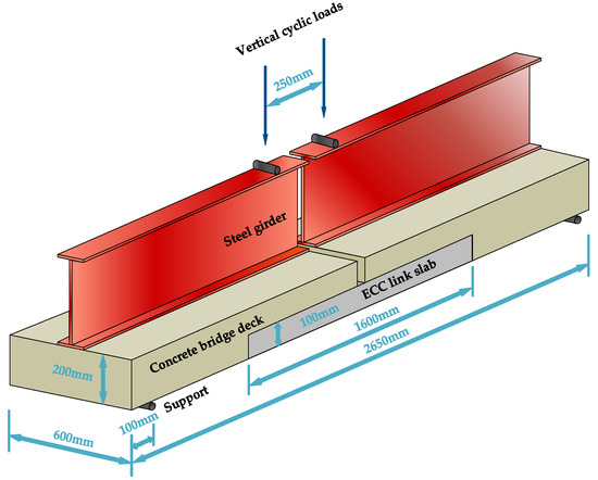
Figure 1.
Experimental continuous bridge deck model.
3.3. Loading Procedure and Measuring Scheme
A monotonic cyclic loading procedure simulating the traffic loads was performed up to the ultimate failure or the rotation angle of 0.04 rad [26]. This test system was operated conforming to the deflection-control method. The deflection increased from zero to the peak value (dpeak) and then decreased to zero within one loading cycle. The growth rate of dpeak was 0.5125mm per cycle (i.e., 0.0005 rad/cycle). As shown in Figure 1, the steel girder ends of the inverted model were subjected to the vertical monotonic cyclic loads. The relationship between applied load (F) and dpeak in each loading cycle was recorded.
As shown in Figure 2, a linear variable differential transformer (LVDT) was installed at the mid location of each ECC link slab (on the top surface) to monitor the vertical deflection. The strain gauges numbered S1, S2, S3, S4, and S5 were placed at equal intervals along the side midline of each ECC link slab. Meanwhile, the strain gauges numbered T1, T2, T3, and T4 were placed along the top midline of each ECC link slab. Additionally, the strains of CFT grids (G1, G2, G3, etc.), CFRP bars (B1, B2, B3, etc.), and reinforcing steels (R1, R2, R3, etc.) embedded in the link slabs were monitored and those measuring points are exhibited in Figure 3 and Figure 4. It should be noted that the healthy measuring points are continuously numbered herein, excluding the broken ones. The relationship between measured strains (ε) and dpeak within each loading cycle was recorded as well. Through the analyses of F-dpeak and ε-dpeak curves, the dependence of strains on each loading step (every 1kN) can be determined to further study the structural performance.
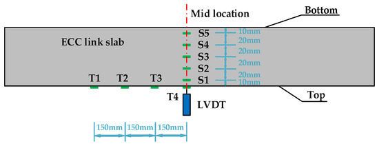
Figure 2.
Strain and displacement measuring points for the inverted engineered cementitious composites (ECC) link slab.
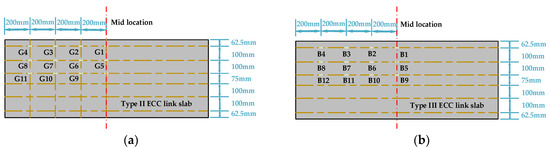
Figure 3.
Strain measuring points for the fiber reinforced polymer (FRP) composites: (a) carbon fiber textile (CFT) grids and (b) carbon fiber reinforced polymer (CFRP) bars.
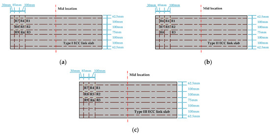
Figure 4.
Strain measuring points for the reinforcing steels embedded in different types of ECC link slabs: (a) Type I ECC link slab; (b) Type II ECC link slab; and (c) Type III ECC link slab.
4. Experimental Data Expansion Using the Response Simulating Interpolation Method
The mid cross section of ECC link slab is the most disadvantageous position under the loading condition presented in Figure 1. Meanwhile, the sample points within the mid cross section are the most intensive. Hence it should be a good attempt to investigate the working states of ECC link slabs based on the GSED sum of mid cross sections. Importantly, these scattered measured strains in this area need to be expanded into spatially continuous strain data without loss of original information before the detection of structural working state.
Space interpolation methods (SIMs) providing access to the data expansion from limited scattered sample points have been widely used in various subjects [37]. SIMs can be grouped into four categories: Global methods (trend surface analysis and regression models), local methods (natural neighbor and splines), geostatistical methods (simple kriging), and mixed methods (trend surface analysis combined with kriging) [38]. Despite the various assumptions and properties of these SIMs, nearly the general estimation formula is shared [37]:
where r(j) is the simulated response value at the interpolated jth point, ωi refers to the weighting function assigned to the ith sample point at which the observed response value is ri, and m represents the total number of sampling points. Consequently it is a matter to determine the weighting function ωi.
Among the various SIMs, the response simulating interpolation method is introduced which makes full use of the important properties of numerical shape function (NSF) simulated by a physical model. According to the discretization concept and the properties of NSF, the weighting function can be derived by numerical simulation [39]. Actually, the numerical simulation generally used for estimating experimental responses can partially reflect the implicit information included in a specific physical model [40]. Hence the combination of numerical simulation and interpolation is of adequate accuracy. The data expanded by a reliable SIM is deemed to be helpful to the investigation on the working state of ECC link slab.
The determination of NSF and the estimation of response field (strains) are implemented following the procedure [39]:
- Divide the area into a certain amount of suitable elements as shown in Figure 5. Although the shape function of each element is estimated, the simulated strain fields assembled with enough small elements can still reflect the strain characteristics of this area exactly with high order continuity. The reason is that the calculation of element stiffness matrices and the assembling of global stiffness equation are based on the virtual displacement principle and the force balance principle, respectively [41].
 Figure 5. Mesh generation.
 - Apply a unit strain at node 1 along the direction at right angle to this area, while the other nodes are fixed along the same direction to restrict rigid body displacement. Then, the simulated strain field solved by static finite element analysis represents the shape function N1, as shown in Figure 6. And it can be expressed by discrete vector N1 = {N1 (1), N1 (2), …, N1 (k), …, N1 (n)}, where N1 (k) is the function value at element node k and n is the total node number.
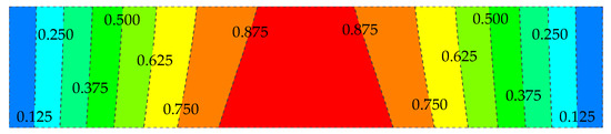 Figure 6. Contour map of shape function N1.
 - Other NSFs (Ni) can be determined in the same way. Given the strain value at each measuring point and the corresponding NSF, the strain field of this area denoted by ε = {ε (1), ε (2), …, ε (n)} can be constructed as following,where m is the number of measured points of strain. The constructed strain field conforming to Castigliano’s theorem is independent of loading paths and linear superposition can be applied to the simulated results with explicit physi-cal meanings.
Data expansion is implemented with the support of finite element analysis software (ANSYS). The models of mid cross sections are created with element Shell 181 for ECC materials and element Beam 188 for reinforcing materials. After meshing the cross sections (60 times 10 = 600 elements), the strain data of each mesh node can be determined following the steps described above and then the corresponding stress can be calculated via constitutive relations. Accordingly, the GESD at each node and the Ej,norm are obtained. Furthermore, the structural response field at a specific loading step can be plotted using the expanded data.
5. Characterization of the ECC Link Slabs’ Working State
5.1. The GSED-Based Investigation into the Working States of ECC Link Slabs
The stress data of each mesh node are calculated via the constitutive relations of different materials as shown in Figure 7.
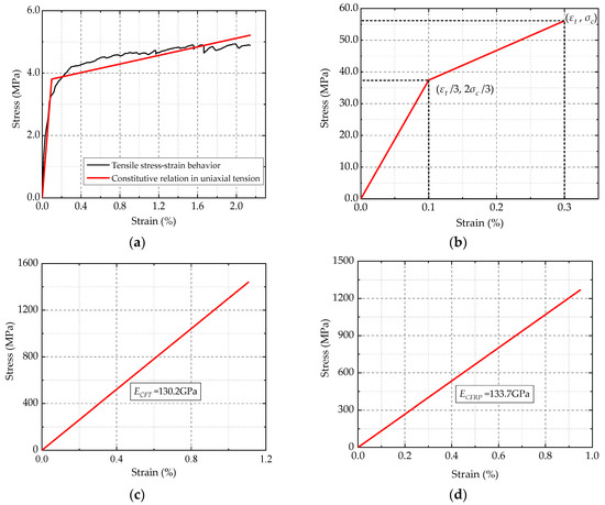
Figure 7.
Constitutive relations of different materials: (a) ECC materials in uniaxial tension; (b) ECC materials in compression; (c) CFT grid; and (d) CFRP bar.
The constitutive relations in uniaxial tension and compression prior to ultimate failure can be described by bilinear curves [42]. The constitutive relation in uniaxial tension is fitted with the tensile stress-strain curve of ECC as shown in Figure 7a [26]. The constitutive relation in compression is established by connecting those specific points as shown in Figure 7b. The unilinear stress-strain relationships of the CFT grid (elastic modulus ECFT =130.2 GPa) and CFRP bar (elastic modulus ECFRP =133.7 GPa) are exhibited in Figure 7c,d, respectively [43,44]. According to these constitutive relations, the stress values are calculated. Thus, the GESD and the Ej,norm are obtained by Equation (1) and Equation (2), respectively.
The Ej,norm-Lj curve, UFk-Lj curve and UBk-Lj curve for Type I ECC link slab are plotted in Figure 8, which embodies the evolving structural performance of ECC link slab from the perspective of energy. By distinguishing the intersections of UFk and UBk curves, the M-K criterion reveals two working state leaps in the Ej,norm-Lj curve. These two mutation points indicate the structural performance transitions of ECC link slab under loads. The first mutation point (M1: Step 9, 9 kN) is identified by investigating the whole Ej,norm-Lj curve. Then, the following mutation point (M2: Step 14, 14 kN) is identified from the Ej,norm-Lj curve segment (from M1 on).
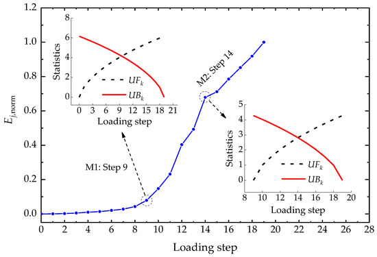
Figure 8.
Ej,norm-Lj curve, UFk-Lj curve, and UBk-Lj curve for Type I ECC link slab.
Similarly, the working state leaps of the other two link slabs are revealed from their Ej,norm-Lj curves, which are shown in Figure 9 together with the curve of Type I ECC link slab for comparison. The two mutation points (M1 and M2) can divide the working state of ECC link slab into different stages:
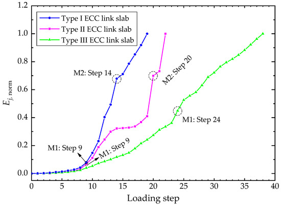
Figure 9.
Ej,norm-Lj curves for the three types of ECC link slabs.
- The elastic stage. As shown in Figure 9, the Ej,norm grows quite slowly and the developing trend is steady before M1, representing a stable stage of ECC link slabs under the simulated traffic loading. Actually, the working behavior within this stage is mostly the elastic response of ECC material properties and cracking was not observed during this period [26]. When the magnitude of load is relatively small, the structural load-bearing capacity is mainly offered by the ECC. The effect of FRP composites is not obvious as the GSED sum of the three ECC link slabs are almost identical in the early phase. The experimental structures are of adequate stiffness and stability within this stage.
- The elastic-plastic stage. The Ej,norm after M1 is relatively greater than that in the elastic stage as shown in Figure 9, speculating on the formation of micro-cracks and crack propagation afterwards. The Ej,norm-Lj curve in this stage is not that smooth due to the multiple cracking behavior of ECC materials [26]. The whole structure has transited into the elastic-plastic stage with local plastic development. It could be comprehended that the critical point M1 between elastic stage and elastic-plastic stage is the yielding point of each ECC link slab, where the working state changes from elasticity to elastoplasticity. The plastic behavior occurs at the 9th loading step for Type I and II ECC link slabs, and the 24th step for Type III ECC link slab. Accordingly, the yielding loads of the three types of ECC link slabs are 9 kN, 9 kN, and 24 kN, respectively. The CFRP bar reinforcement condition raises the yielding load of ECC link slab by 166.67%. Although Type I and Type II ECC link slabs yield to the same magnitude of load, the Ej,norm of the latter is relatively slow to reach M2. Compared with Type I ECC link slab, ECC link slab strengthened by CFT is observed to produce an extended elastic-plastic period. The structural toughness index T is proposed herein to quantify the energy dissipation capacity of ECC link slab working in the elastic-plastic stage, which is formulated as following:where EM1,norm and EM2,norm are the GSED sum at the loading steps corresponding to M1 and M2, respectively; S is the span of elastic-plastic stage (the difference in loading steps between M1 and M2). The results are illustrated in Figure 10 and it is evident that Type II ECC link slab exhibits superior structural toughness to Type I ECC link slab. The structural toughness index is raised by 78.79% owing to the CFT grid reinforcement, which could be attributed to the enhanced deformation capacity and cracking resistance.
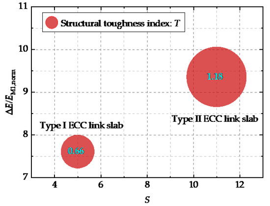 Figure 10. Structural toughness indices of Type I and Type II ECC link slabs.
 - The degrading stage. Despite the presence of plastic behavior in some parts of link slabs, the whole structures are able to bear increasing loads until M2. The Ej,norm of Type I and Type II ECC link slabs begin to increase rapidly and sharply at M2 as shown in Figure 9, implying that the whole structures qualitatively leap to a new stage different from the previous ones. The number of cracks remained unchanged while the crack width and extent of cracking kept increasing [26]. It demonstrates that the ECC materials did not exhibit strain hardening characteristics and multiple cracking behavior any more. Moreover, forces cannot effectively be transferred between ECC and CFT grid after M2. The loss in normal properties of materials leads to the degrading structural performance within this stage. Therefore, the load corresponding to the critical point M2 can be defined as the structural failure load of the link slab. Actually, this updated failure is the initiation of structural performance deterioration (i.e., the initial structural failure), which is different from the existing structural ultimate failure. From this critical point on, the interfacial bonding between components and structural integrity start to be gradually impaired. This updated concept of failure is reliable as it is revealed by delving into the structural working state characteristics complying with the natural course from quantitative change to qualitative change. It is noted that the critical point M2 is not observed for Type III ECC link slab based on the existing test data. In other words, the degrading stage discussed herein is not applicable to Type III ECC link slab. Both the high flexural stiffness of CFRP bars and their intact bonding with ECC materials help to maintain the desired load capacity and ductility after M1 [26]. The development of local plastic deformation in Type III ECC link slab was far from enough to affect the working behavior of the whole structure, hence the initial failure point has not been reached in this investigation. Provided that the time-varying test data is complete, the initial structural failure load can be accurately predicted for Type III ECC links slab.
5.2. Working State Modes Based on Strains and Displacements
The structural responses at representative locations should exhibit some features relevant to the working state of the whole structure. The working state modes are defined as the dependences of strains/displacements measured in the experiment on both the locations of measuring points and the loading steps, which are formulated as follows,
where sij and dij refer to the strains and displacements of the ith measuring point at the jth loading step, respectively; m is the number of measuring points and n is the number of loading steps. The Type II ECC link slab is exampled to demonstrate the working state modes since it contains all series of strain measuring points as well as the two critical points through the whole working state. The working state mode of Type II ECC link slab can be divided into five groups, including the strains measured along the top midline (Stop), the strains measured along the side midline (Sside), the strains of the CFT grids (Sgrid), the strains of the reinforcing steels embedded in the link slab (Ssteel), and the displacement at the mid location of the link slab (Dm). The strain-based working state modes are plotted in Figure 11, where the local working behavior characteristics can be perceived in terms of ‘‘shape” and ‘‘incremental amplitude”. The displacement-based working state mode is represented by the relationship between Dm and loading steps, as shown in Figure 12.
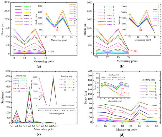
Figure 11.
Strain-based working state modes for various groups: (a) Stop-based working state mode; (b) Sside-based working state mode; (c) Sgrid-based working state mode; and (d) Ssteel-based working state mode.
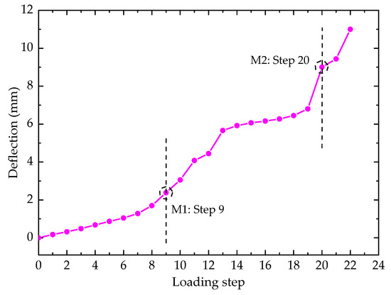
Figure 12.
Dm-based working state mode.
Figure 11 vividly exhibits the development of working state modes where the red dash lines correspond to the critical loading steps of yielding/initial failure for Type II ECC link slab. It can be seen from Figure 11a that Stop grows at quite a slow pace before M1 and then a sudden change in the incremental amplitude of Stop is observed around M1. Thereafter, another mutation of Stop happens in the wake of M2. The developing rate of the Stop at T1 and T3 is faster than the others, indicating that these zones are the weak parts of Type II ECC link slab.
The strains along the side grow obviously faster than those along the top, as shown in Figure 11b. Before M1, the strain values at the five points are basically in a straight line (approximately at the same level), due to the flat state within this zone. After M1, the strains near the top surface develop much faster than those interior ones, indicating that the flat state begins to feature the nonlinearity to some extent. This could be attributed to the formation of micro-cracks around M1. The development of strains is accelerated with the crack propagation after M1. Moreover, all the measuring points along the side have transited into the tension state after M2 and the subsequent plastic deformation is considerable. It is illustrated in Figure 11b that the qualitative transformation from the sectional flat state to the non-flat state occurs when the load reaches the critical point M1 and this irreversible change becomes more remarkable after M2.
It is explicitly shown in Figure 11c that the two mutations take place at those measuring points close to the mid location of Type II ECC link slab, such as G1 and G2. Most of the strains develop steadily and change with small increments. The CFT grid alone is less sensitive to the working state leaps originating from the evolution of ECC material properties. Besides, the overall strain behavior of reinforcing steels encounters the mutation at M1 though a few measured strains are inconsistent with it as shown in Figure 11d. The other mutation feature of Ssteel-based working mode is distinctly observed at M2 and the mutated forms can be particularly expressed by the change of curve profile and incremental amplitude.
As for the working state mode based on Dm as shown in Figure 12, an evident state leap can be found at M2. However, the mutation characteristic at M1 is not clearly shown in the Dm-Lj curve, implying that the plastic deformation at M1 cannot match the influence of initial structural failure on the macroscopic displacement.
In general, the working state modes focusing on the local strains of components and the structural deflection can be employed as a valuable demonstration of the evolving structural working state. It could be reasonable to define M1 as the yielding point signifying that the working state mode of ECC link slab begins to change from elastic state into elastic-plastic state, and M2 as the initial structural failure point after which the structural working performance is badly weakened.
5.3. Characteristics of Structural Strain Fields
The strain fields of ECC link slabs can be simulated with the expanded data. The mid cross section of Type II ECC link slab stands as a perfect example. The structural working state leaps can be revealed by its strain field characteristics around the critical points. Figure 13 exhibits the strain fields at different loading steps around the yielding point (M1) and the initial failure point (M2) respectively, where different colors represent different levels of strains and the isopleth curve links the strains at the same level.
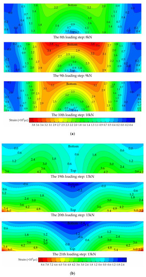
Figure 13.
Strain fields of the mid cross section of Type II ECC link slab: (a) around the yielding point M1 and (b) around the initial failure point M2.
It can be seen from Figure 13a that the whole cross section is basically governed by tensile strain at the 8th loading step, though a small proportion of it stays in compression state. At the 9th loading step, dramatic growth of tensile strain is observed, and the yielding point is reached in most regions. However, these strains decrease at the 10th loading step, as a result of the bridging effect of PVA fibers. Thereafter, tensile forces are shared by more regions hence the tensile strains are evenly distributed within this cross section up to the 19th loading step, as shown in Figure 13b. It can be inferred that the link slab is mainly in tension state after the yielding point. Besides, tensile forces are gradually transferred to the CFT grid as it can be observed from Figure 13b that tensile strains of the regions where CFT grid exists have increased and the shape of isopleth curves has changed. At the 20th step, this cross section suddenly leaps into a state totally different from the previous ones, where nearly half area of this cross section is under compression. ECC materials in this zone cannot withstand tensile forces because of high extent of cracking and extensive fiber fracture. Actually, the tensile force bearing capacity is largely provided by the CFT grid. The initial failure occurs at this loading step and the strains keep increasing until the destruction of Type II ECC link slab.
5.4. Development of Structural Internal Forces
The internal forces of the mid cross section of Type II ECC link slab can be determined using the data expanded by the response simulating interpolation method as well. The dependences of axial force/bending moment on the loading steps are plotted in Figure 14, where the two critical points (M1 and M2) are marked. It can be seen from Figure 14a that the growth of axial force gradually slows down around M1 because compressive stresses are rising faster than tensile stresses at this time, which is consistent with the characteristics of structural strain fields. This plateau lasts until the 19th loading step and a rapid change from tension to compression is observed at M2, demonstrating the occurrence of initial structural failure. As shown in Figure 14b, the level of bending moment is very low during the early period when this cross section is mainly influenced by axial tensile forces. There is a slight increase in the bending moment from M1 on, corresponding to the rise in compressive strains at the bottom as shown in Figure 13a. Moreover, the bending moment presents a considerable increase at M2. Generally, the developing trend of internal forces evidence the qualitative change of working state around the critical points.
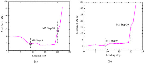
Figure 14.
Internal forces of the mid cross section of Type II ECC link slab: (a) the axial force and (b) the bending moment.
6. Conclusions
Structural working state theory and attached methods can effectively reveal some unseen features from the experimental and expanded data. The working states of three experimental ECC link slab models were investigated to achieve the following conclusions:
- Advanced mathematical modeling technique based on the GSED for characterizing the working states of ECC link slabs was used successfully and structural working state leaps could be identified by the M-K criterion. Meanwhile, these leap features were verified by the strain/displacement-based working state modes, as well as the development of structural strain fields and internal forces. The working state leaps complying with the natural course from quantitative change to qualitative change indicate the essential evolution of structural performance governed by the material attributes.
- It was revealed that Type I and Type II ECC link slabs working through the whole loading process had three different working stages with two critical points, i.e., the yielding point and the initial structural failure point. The yielding point is a transition of structural working state between being elastic and elastic-plastic. The ECC link slabs working in the elastic-plastic stage could still withstand increasing loads despite the growth of cracks. The initial structural failure point is the origin of structural performance deterioration and ECC link slabs rapidly became closer to the ultimate failure from this point on.
- Type II and Type III ECC link slabs benefitted more than Type I ECC link slab from the FRP reinforcements. The remarkable rise in yielding load (166.67%) was obtained from ECC link slab incorporating CFRP bars and the structural toughness index was raised by 78.79% owing to the CFT grid reinforcement.
- In summary, the investigation on ECC link slabs’ working states explores a new way to structural analysis and the information involved in working state can make important contributions to the improvement of structural design.
Author Contributions
Formal analysis, J.Z. and J.S. (Jiyang Shen); Investigation, J.Z., J.S. (Jiyang Shen) and X.Y.; Methodology, J.S. (Jun Shi); Resources, J.Z. and W.W.; Writing—original draft, J.Z.; Writing—review and editing, J.S. (Jun Shi) and G.Z.
Funding
This research was funded by National Natural Science Foundation of China, grant number 51608069.
Acknowledgments
The authors would like to express their gratitude to Lifei Zhang for carrying out the excellent experiment on bridge deck models and detailing the test data. And many thanks to all members of the HIT 504 office for their useful suggestions.
Conflicts of Interest
The authors declare no conflict of interest.
References
- Chen, B.; Zhuang, Y.; Briseghella, B. Jointless Bridges; Communications Press: Beijing, China, 2013. (In Chinese) [Google Scholar]
- Alampalli, S.; Yannotti, A.P. In-service performance of integral bridges and jointless decks. Transp. Res. Rec. J. Transp. Res. Board 1998, 1624, 1–7. [Google Scholar] [CrossRef]
- Au, A.; Lam, C.; Au, J.; Tharmabala, B. Eliminating deck joints using debonded link slabs: Research and field tests in ontario. J. Bridge Eng. 2013, 18, 768–778. [Google Scholar] [CrossRef]
- Caner, A. Behavior and design of link slabs for jointless bridge decks. PCI J. 1998, 43, 68–81. [Google Scholar] [CrossRef]
- Hou, M.; Hu, K.; Yu, J.; Dong, S.; Xu, S. Experimental study on ultra-high ductility cementitious composites applied to link slabs for jointless bridge decks. Compos. Struct. 2018, 204, 167–177. [Google Scholar] [CrossRef]
- Li, V.C.; Wu, H.C. Micromechanics based design for pseudo strain-hardening in cementitious composites. In Proceedings of the 9th Conference on Engineering Mechanics, College Station, TX, USA, 24–27 May 1992. [Google Scholar]
- Maalej, M.; Hashida, T.; Li, V.C. Effect of fiber volume fraction on the off-crack-plane fracture energy in strain-hardening engineered cementitious composites. J. Am. Ceram. Soc. 1995, 78, 3369–3375. [Google Scholar] [CrossRef]
- Zhong, J.; Shi, J.; Shen, J.; Zhou, G.; Wang, Z. Engineering properties of engineered cementitious composite and multi-response optimization using PCA-based Taguchi method. Materials 2019, 12, 2402. [Google Scholar] [CrossRef]
- Sahmaran, M.; Li, M.; Li, V.C. Transport properties of engineered cementitious composites under chloride exposure. ACI Mater. J. 2007, 104, 604–611. [Google Scholar] [CrossRef]
- Zhong, J.; Shi, J.; Shen, J.; Zhou, G.; Wang, Z. Investigation on the failure behavior of engineered cementitious composites under freeze-thaw cycles. Materials 2019, 12, 1808. [Google Scholar] [CrossRef]
- Maalej, M.; Quek, S.T.; Ahmed, S.F.U.; Zhang, J.; Lin, V.W.J.; Leong, K.S. Review of potential structural applications of hybrid fiber engineered cementitious composites. Constr. Build. Mater. 2012, 36, 216–227. [Google Scholar] [CrossRef]
- Choi, W.C.; Yun, H.D.; Cho, C.G.; Feo, L. Attempts to apply high performance fiber-reinforced cement composite (HPFRCC) to infrastructures in South Korea. Compos. Struct. 2014, 109, 211–223. [Google Scholar] [CrossRef]
- Zhang, J.; Maalej, M.; Quek, S.T. Performance of hybrid-fiber ECC blast/shelter panels subjected to drop weight impact. J. Mater. Civ. Eng. 2007, 19, 855–863. [Google Scholar] [CrossRef]
- Cho, C.G.; Kim, Y.Y.; Feo, L.; Hui, D. Cyclic responses of reinforced concrete composite columns strengthened in the plastic hinge region by HPFRC mortar. Compos. Struct. 2012, 94, 2246–2253. [Google Scholar] [CrossRef]
- Maalej, M.; Chhoa, C.Y.; Quek, S.T. Effect of cracking, corrosion and repair on the frequency response of RC beams. Constr. Build. Mater. 2010, 24, 719–731. [Google Scholar] [CrossRef]
- Mihashi, H.; Ahmed, S.F.U.; Kobayakawa, A. Corrosion of reinforcing steel in fiber reinforced cementitious composites. J. Adv. Concr. Technol. 2011, 9, 159–167. [Google Scholar] [CrossRef]
- Li, V.C. Integrated structures and materials design. Mater. Struct. 2007, 40, 387–396. [Google Scholar] [CrossRef]
- Kim, Y.Y.; Fischer, G.; Li, V.C. Performance of bridge deck link slabs designed with ductile engineered cementitious composite. ACI Struct. J. 2004, 101, 792–801. [Google Scholar] [CrossRef]
- Wing, K.M.; Kowalsky, M.J. Behavior, analysis, and design of an instrumented link slab bridge. J. Bridge Eng. 2005, 10, 331–344. [Google Scholar] [CrossRef]
- Li, V.C.; Lepech, M. Field demonstration of durable link slabs for jointless bridge decks based on strain-hardening cementitious composites. In Michigan Department of Transportation Research Report RC 1471; Michigan Department of Transportation: Lansing, MI, USA, 2005. [Google Scholar]
- Lepech, M.D.; Li, V.C. Application of ECC for bridge deck link slabs. Mater. Struct. 2009, 42, 1185–1195. [Google Scholar] [CrossRef]
- Benmokrane, B.; El-Salakawy, E.; El-Ragaby, A.; Lackey, T. Designing and testing of concrete bridge decks reinforced with glass FRP bars. J. Bridge Eng. 2006, 11, 217–229. [Google Scholar] [CrossRef]
- El-Salakawy, E.; Benmokrane, B.; El-Ragaby, A.; Nadeau, D. Field investigation on the first bridge deck slab reinforced with glass FRP bars constructed in Canada. J. Compos. Constr. 2005, 9, 470–479. [Google Scholar] [CrossRef]
- Zheng, Y.; Zhang, L.; Xia, L. Investigation of the behaviour of flexible and ductile ECC link slab reinforced with FRP. Constr. Build. Mater. 2018, 166, 694–711. [Google Scholar] [CrossRef]
- Berg, A.C.; Bank, L.C.; Oliva, M.G.; Russell, J.S. Construction and cost analysis of an FRP reinforced concrete bridge deck. Constr. Build. Mater. 2006, 20, 515–526. [Google Scholar] [CrossRef]
- Zhang, L. Investigation of the Behaviour of Fibre Reinforced Polymer (FRP) Reinforced Engineered Cementious Composites (ECC) Link Slab in Bridge Deck Structures. Master’s Thesis, South China University of Technology, Guangdong, China, 2017. (In Chinese). [Google Scholar]
- Zhou, G.; Rafiq, M.Y.; Bugmann, G.; Easterbrook, D.J. Cellular automata model for predicting the failure pattern of laterally loaded masonry wall panels. J. Comput. Civ. Eng. 2006, 20, 400–409. [Google Scholar] [CrossRef]
- Zhou, G.; Pan, D.; Xu, X.; Rafiq, Y.M. Innovative ANN technique for predicting failure/Cracking load of masonry wall panel under lateral load. J. Comput. Civ. Eng. 2010, 24, 377–387. [Google Scholar] [CrossRef]
- Zhang, Y.; Zhou, G.; Xiong, Y.; Rafiq, M.Y. Techniques for predicting cracking pattern of masonry wallet using artificial neural networks and cellular automata. J. Comput. Civ. Eng. 2010, 24, 161–172. [Google Scholar] [CrossRef]
- Huang, Y.; Zhang, Y.; Zhang, M.; Zhou, G. Method for predicting the failure load of masonry wall panels based on generalized strain-energy density. J. Eng. Mech. 2014, 140, 04014061:1–04014061:6. [Google Scholar] [CrossRef]
- Chattopadhyay, G.; Chakraborthy, P.; Chattopadhyay, S. Mann-Kendall trend analysis of tropospheric ozone and its modeling using ARIMA. Theor. Appl. Climatol. 2012, 110, 321–328. [Google Scholar] [CrossRef]
- Rehman, S. Long-term wind speed analysis and detection of its trends using Mann-Kendall test and linear regression method. Arab. J. Sci. Eng. 2013, 38, 421–437. [Google Scholar] [CrossRef]
- Hamed, K.H. Exact distribution of the Mann-Kendall trend test statistic for persistent data. J. Hydrol. 2009, 365, 86–94. [Google Scholar] [CrossRef]
- Mann, H.B. Nonparametric tests against trend. Econometrica 1945, 13, 245–259. [Google Scholar] [CrossRef]
- Kendall, M.G.; Jean, D.G. Rank Correlation Methods; Oxford University Press: New York, NY, USA, 1990. [Google Scholar]
- Hirsch, R.M.; Slack, J.R.; Smith, R.A. Techniques of trend analysis for monthly water quality data. Water Resour. Res. 1982, 18, 107–121. [Google Scholar] [CrossRef]
- Li, J.; Heap, A.D. Spatial interpolation methods applied in the environmental sciences: A review. Environ. Model. Softw. 2014, 53, 173–189. [Google Scholar] [CrossRef]
- Luo, W.; Taylor, M.C.; Parker, S.R. A comparison of spatial interpolation methods to estimate continuous wind speed surfaces using irregularly distributed data from England and Wales. Int. J. Climatol. 2008, 28, 947–959. [Google Scholar] [CrossRef]
- Shi, J.; Zheng, K.; Tan, Y.; Yang, K.; Zhou, G. Response simulating interpolation methods for expanding experimental data based on numerical shape functions. Comput. Struct. 2019, 218, 1–8. [Google Scholar] [CrossRef]
- Hauser, C.; Walz, B.; Maincon, P.; Barnardo, C. Application of inverse FEM to earth pressure estimation. Finite Elem. Anal. Des. 2008, 44, 705–714. [Google Scholar] [CrossRef]
- Zienkiewicz, O.C.; Taylor, R.L.; Zhu, J.Z. The Finite Element Method: Its Basis and Fundamentals, 7th ed.; Butterworth-Heinemann: Oxford, UK, 2013. [Google Scholar]
- Maalej, M.; Li, V.C. Flexural tensile-strength ratio in engineered cementitious composites. J. Mater. Civ. Eng. 1994, 6, 513–528. [Google Scholar] [CrossRef]
- Tran, M.T.; Vu, X.H.; Ferrier, E. Experimental and analytical analysis of the effect of fibre treatment on the thermomechanical behaviour of continuous carbon textile subjected to simultaneous elevated temperature and uniaxial tensile loadings. Constr. Build. Mater. 2018, 183, 32–45. [Google Scholar] [CrossRef]
- Soric, Z.; Kisicek, T.; Galic, J. Deflections of concrete beams reinforced with FRP bars. Mater. Struct. 2010, 43, 73–90. [Google Scholar] [CrossRef]


© 2019 by the authors. Licensee MDPI, Basel, Switzerland. This article is an open access article distributed under the terms and conditions of the Creative Commons Attribution (CC BY) license (http://creativecommons.org/licenses/by/4.0/).