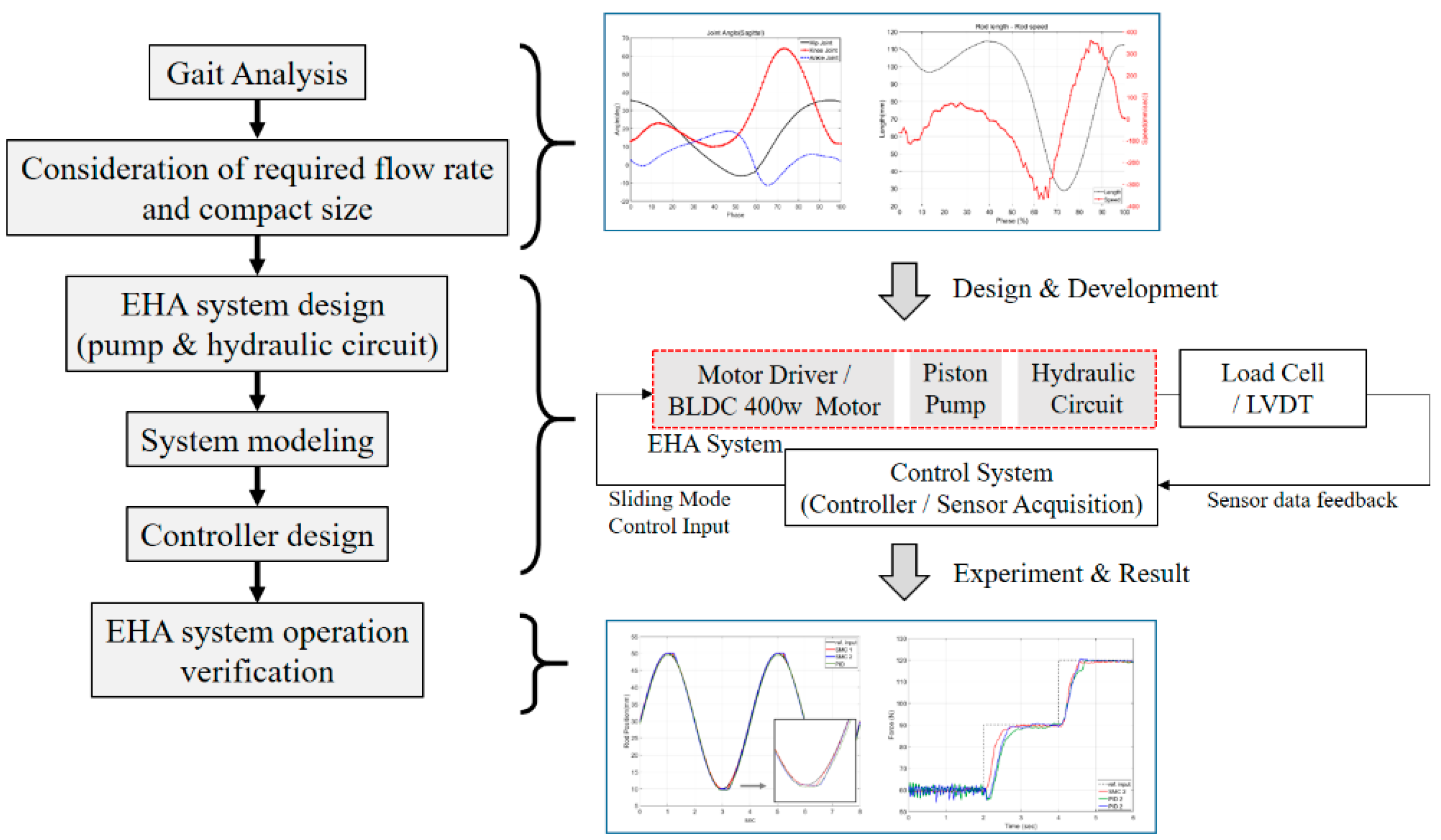
Abstract
Exoskeleton robots have been developed in various fields and are divided into electric and hydraulic exoskeletons according to the actuator type. In the case of hydraulic robots, because a unidirectional pump is applied, there are limitations to the wearer’s walking. In addition, robot systems are complicated, because a directional control valve is required to change the direction of the actuator. To solve these problems, we designed the electro-hydraulic actuator (EHA) system which has both the hydraulic and electric advantages. The EHA system consists of a hydraulic bidirectional pump, a motor, a hydraulic cylinder, and various valves. For the development of the piston pump, we analyzed the gait cycle and considered the flow rate and pulsation rate. In order to reduce the size and weight of the EHA system, the valves were made from one manifold, and the hydraulic circuit was simplified. We verified that the developed EHA system is applicable to robots through position and force control experiments. Because the hydraulic system is nonlinear, we designed a sliding mode control (SMC) and compared it with the proportional integral derivative (PID) controller.
1. Introduction
Exoskeleton robot has been developed in various fields of industrial and rehabilitation training applications. These robot systems are largely divided into muscle strengthening and muscle assisting systems, according to the purpose of use. Muscle-assisted exoskeleton robots are applied to rehabilitation training and welfare fields for paralyzed patients and elderly people to provide muscular strength. In other words, these exoskeleton robots assist people to walk without help. So, the actuator in the exoskeleton robot needs only power to support the weight of a wearer. Therefore, it can be operated and powered by most electric actuators [1,2,3,4]. Muscle-strengthening exoskeleton robots are used in industrial applications to carry heavy loads that are difficult to perform using human strength. They are classified into electric and hydraulic type considering their use in the robot.
In the case of the electric type, it is a structure in which a motor and a reducer are combined, and it operates the robot by the power of the motor. A large reducer with a large gear ratio is installed additionally for high power, and each joint has a complicated structure [5,6,7]. However, this increases the noise, volume, and weight of the robot as well as its development costs. Also, the range of motion of the joint is limited and the wearer feels uncomfortable. Because the power is small compared to the hydraulic type, it is not applicable to the muscle strengthening exoskeleton robots.
On the other hand, hydraulic types can produce higher power than the electric types and are inexpensive. Hydraulic systems consist of several hydraulic parts, such as servo valves, which control the unidirectional pump and flow rate [8,9]. However, hydraulic systems are complicated and thus difficult to maintain. Because the hydraulic pump is unidirectional, it must continue to operate, regardless of whether or not the hydraulic actuator operates. Because of this problem, noise and vibration occur. Also, it consumes energy constantly, which lowers the energy efficiency. However, this has been studied in the applications of muscle-strengthening robots. This is because hydraulic pump robots are more powerful than electric type robots [9,10,11]. Most muscle strengthening exoskeleton robots use conventional hydraulic systems because of the high power ratio of torque and mass, and these systems use a unidirectional pump and a control valve. Because the pump cannot change direction, when the robot strengthens a muscle during a Sit to Stand in stand phase, an actuator is driven in active mode, but in other cases of a stand to sit in the swing phase, it is operated in passive mode. That is, for the wearer to bend the knee, a controller opens solenoid valves and the wearer has to bend the knee joint of the robot. This makes the wearer feel tired and has the disadvantage of the slow response [12,13,14]. Such conventional hydraulic systems are complicated because of solenoid valves and have problems such as leakages. In addition, many gear pumps apply to exoskeleton robots. The gear pumps have the limitation of high-speed rotation and have the disadvantage of large noise and vibration instead of a simple structure. It is also difficult to produce high pressures because of the many internal leakages [15,16,17].
Recently, in order to solve the problems of the existing hydraulic systems and electric system, an electro-hydraulic actuator (EHA) which combines electric and hydraulic systems was replaced [18]. This system has more power and higher energy-efficiency than the electric type. Moreover, the system is equipped with a bidirectional pump, and the speed and position of the hydraulic actuator can be controlled through a motor attached to the pump. This EHA provides a high level of power, has the advantages of a conventional hydraulic system, and solves the disadvantages of the hydraulic and electric types. Compared with the hydraulic system, the EHA system does not need a directional control valve. Because the hydraulic circuit is simple, it is easy to manage leakage, and manufacturing costs are reduced. Therefore, it has been applied to various fields [10,19,20].
Therefore, the EHA system applied to the exoskeleton robot can solve the problems of the electric exoskeleton robot and the hydraulic exoskeleton robot. Because the robot’s knee joint is equipped with a cylinder, not a motor, it does not need an additional reducer. Also, the hydraulic circuit is simple. As a result, the size and weight can be reduced, and the maintenance is easy. Therefore, in order to solve the problems of the conventional hydraulic exoskeleton robots, it is necessary to study an EHA that is applicable to robots with a bidirectional piston pump.
In this paper, we developed an EHA system for an exoskeleton robot considering volume, size, and weight. We designed the controller and verified its performance. First, a bidirectional piston pump was designed to overcome the limitation of the gear pump. The piston pump is advantageous for high-speed rotation and can obtain high pressure compared with the gear pump. Because the wearer lifts heavy weight on the back and moves, the hydraulic system needs to be minimized in weight and volume. For this development, we analyzed the gait cycles of ordinary people using data relative to gait analysis. Based on the results, we determined the stroke length of a hydraulic cylinder and the discharge flow rate of the pump. Also, a hydraulic pump was designed considering the pulsation rate, which affects the performance of the hydraulic system. In addition, we designed the hydraulic circuit with a simple structure and made one manifold in many valves to make them smaller and lighter. Therefore, the EHA system was developed by integrating the motor, pump, and hydraulic valves into one system. Because this hydraulic system has many uncertainties, robust control is required to minimize the effect of nonlinearity. As a result, we proposed sliding mode control for this and designed the control based on the mathematical modeling of the EHA system.
So, the flow of the paper is shown in Figure 1 and its composition is as follows. The developed axial piston pump is presented in Section 2, and the hydraulic circuit is presented in Section 3. Additionally, we modeled the system mathematically, and this is presented in Section 4. Finally, we designed a controller and verified the performance of the proposed EHA system via experiments, which is presented in Section 5.
Figure 1.
The composition and flow of a paper.
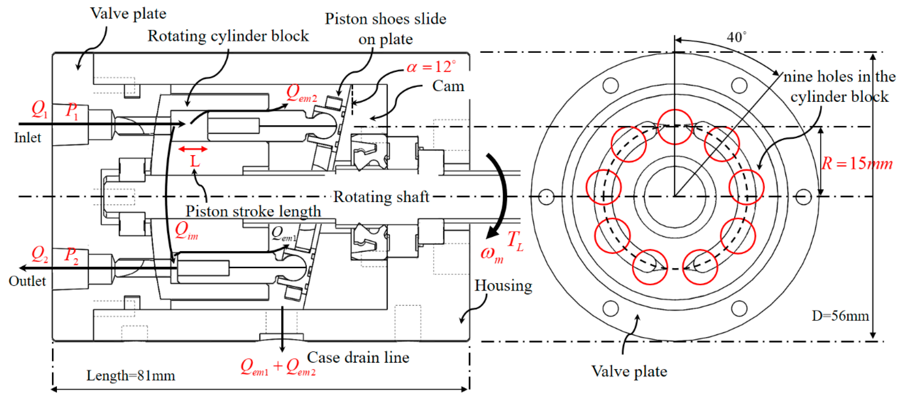
2. Design of Axial Piston Pump
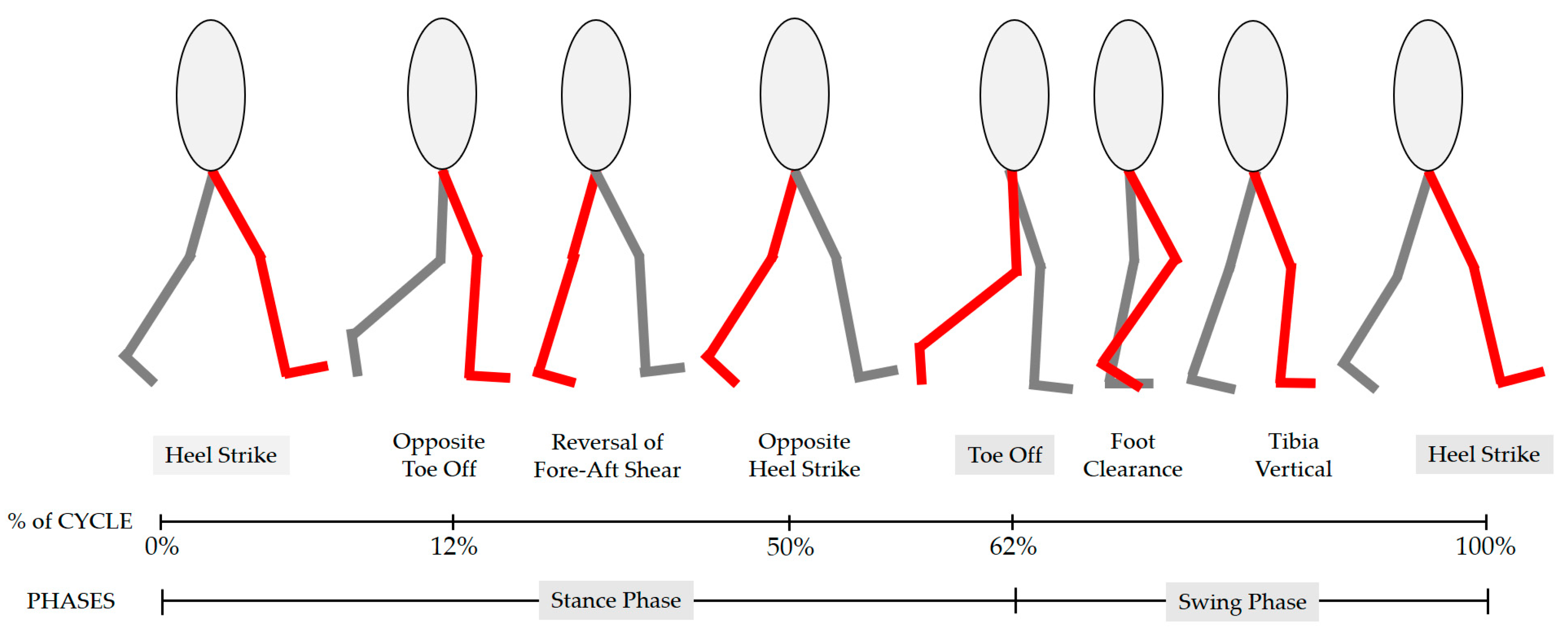
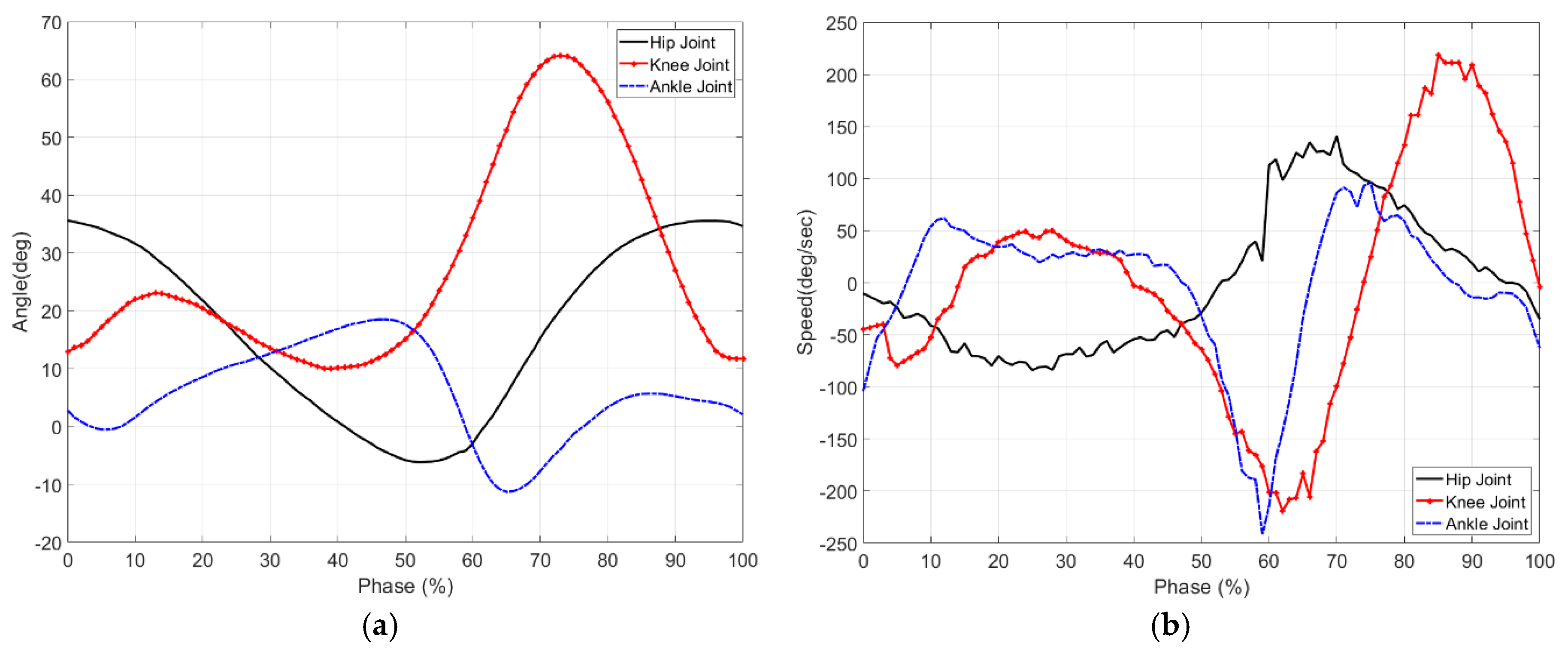
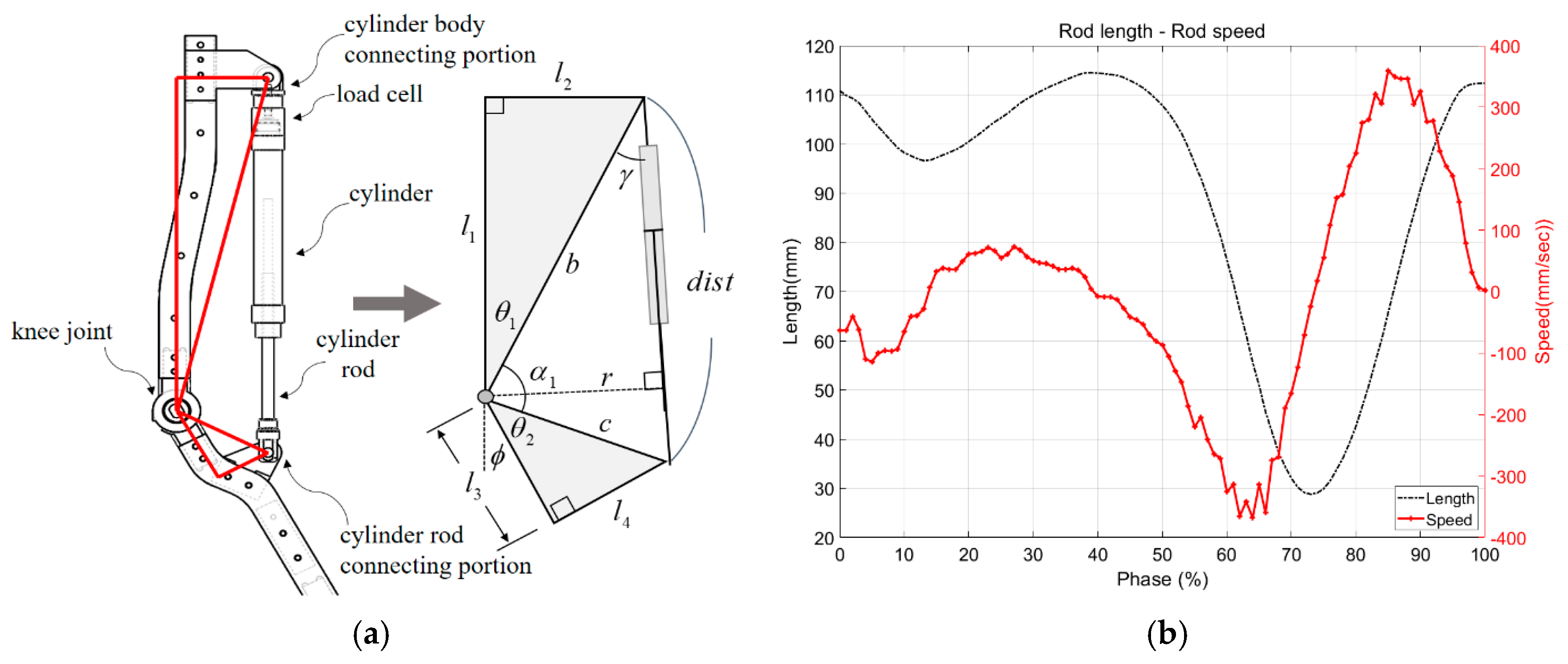
2.1. Analysis of Gait and Calculation of the Required Flow Rate
Analyzing a wearer’s gait cycle is very important when developing an exoskeleton robot. This is because the specifications of an actuator in the robot can be determined, and a control algorithm and the intention of the wearer can be grasped. This study aims to develop an EHA system that can be applied to an exoskeleton robot that can move with a 40 kg mass. For this purpose, specifications of the pump were determined by calculating the flow rate according to the analysis. As shown in Figure 2, the gait cycle is divided into the stance phase and swing phase. The start of the stance phase is a heel strike, and during this phase, the exoskeleton robot supports the weight. This stage occupies 60% of the entire walking cycle. After that, the swing phase starts from the moment of toe-off [21].
Figure 2.
The gait cycle is divided into the stance phase and swing phase.
At swing phase, the exoskeleton robot moves with the wearer according to the wearer’s intentions. This phase is the section in which the robot is under force control by interaction with the wearer. The angular velocity of the knee joint is the fastest in this phase. Therefore, the hydraulic actuator on the knee joint should work accordingly. Figure 3 shows that the angle and angular velocity of each joint plotted on the sagittal plane based on the data of “gender differences in three-dimensional gait analysis data from 98 healthy Korean adults [22].” This gait study included people 175 cm tall, and one cycle in the stage is 1.5 s, expressed as 0% to 100%. After 60% of the walking cycle, the swing phase starts (toe-off). The angular velocity is about 210 deg/s. When the stance phase starts (at the heel strike), the angular velocity is about −225 deg/s. The change in the angle can be seen from 10 to 65 degrees. In order to be implemented for general people, the angular velocity of the robot knee should be about 230 deg/s.
Figure 3.
The angle and angular velocity of each joint in the sagittal plane according to the gait cycle: (a) is the angle, and (b) is the angular velocity.
Before developing an EHA system for an exoskeleton robot, we assumed that the hydraulic actuator applied only to the robot’s knee and that the robot wearer’s height is 175 cm tall. The knee of the exoskeleton robot is bent and stretched by the forward and backward motion of the hydraulic cylinder. The knee joint, cylinder body connecting portion, and cylinder rod connecting portion formed two triangles, as shown by the simple drawing in Figure 4a. The lengths of the links are , , , and respectively. The angle of the knee joint is , and we can see that the angle varies by 65 degrees (Figure 3a). The resulting change in the cylinder rod can be represented by . We were able to obtain the change of the actual length in the cylinder, and the maximum rod length of the cylinder was about 115 mm. Based on this, the cylinder with the 120 mm stroke length was applied (Figure 4b). As a result, it could be driven to the angle of the knee joint for the wearer.
Figure 4.
(a) This is the knee structure of the exoskeleton robot and its simplification. (b) This is the change in length of the cylinder and the speed.
The displacement volume of an axial piston pump differs depending on the stroke length of the piston and the number of pistons. As shown in Figure 5, the radius of the dotted line in the valve plate is , the cam angle is , and then a piston stroke length is as shown below [23]:
Figure 5.
Structure of an axial piston pump. The pump consists of a drive shaft, a valve plate, a cylinder block, pistons, piston shoes, and a swash plate.
The cross-section area of the piston is , the number of the piston is , and the displacement volume is expressed as follows:
When the piston rotates by from the bottom dead center (BDC), the piston moving is expressed as:
The velocity of the piston becomes in Equation (3). is the angular velocity of the cylinder block. At this time, the instantaneous discharge amount of the pump is expressed as follows [23]:
If the number of pistons is an even number, and the discharge amount is
If it is an odd number, and the discharge amount is
If is an even number, the cylinder block pulsates times when it rotates once, but if it is an odd number, it pulsates times. The pulsation rate is expressed as , and when is an even number, it is as follows:
When it is an odd number, it is as follows:
The pulsation rate of the discharge amount according to the number of pistons is calculated as shown in Table 1.
Table 1.
Pulsation rate according to the number of pistons.
For the calculated pulsation rate , as the number of pistons increases, the pulsation rate becomes small. However, if it is an odd number, it becomes much smaller. Therefore, it is common to choose an odd number of pistons, in terms of the pulsation rate. In this study, nine pistons were selected considering the size of the piston pump. The inner diameter of each piston is 6 mm and the cam angle is 12 degrees. At this time, according to Equation (2) and the number of pistons, the displacement volume discharged is about 1.5 cc in one rotation. Considering the maximum speed of the cylinder rod, the required discharge flow rate is about 113 cc/s. At this time, because the discharge amount of the pump in one revolution is about 1.5 cc, the pump speed had to be over 75.3 rev/s. That is, the speed of the motor needed to be 4520 rpm or more.
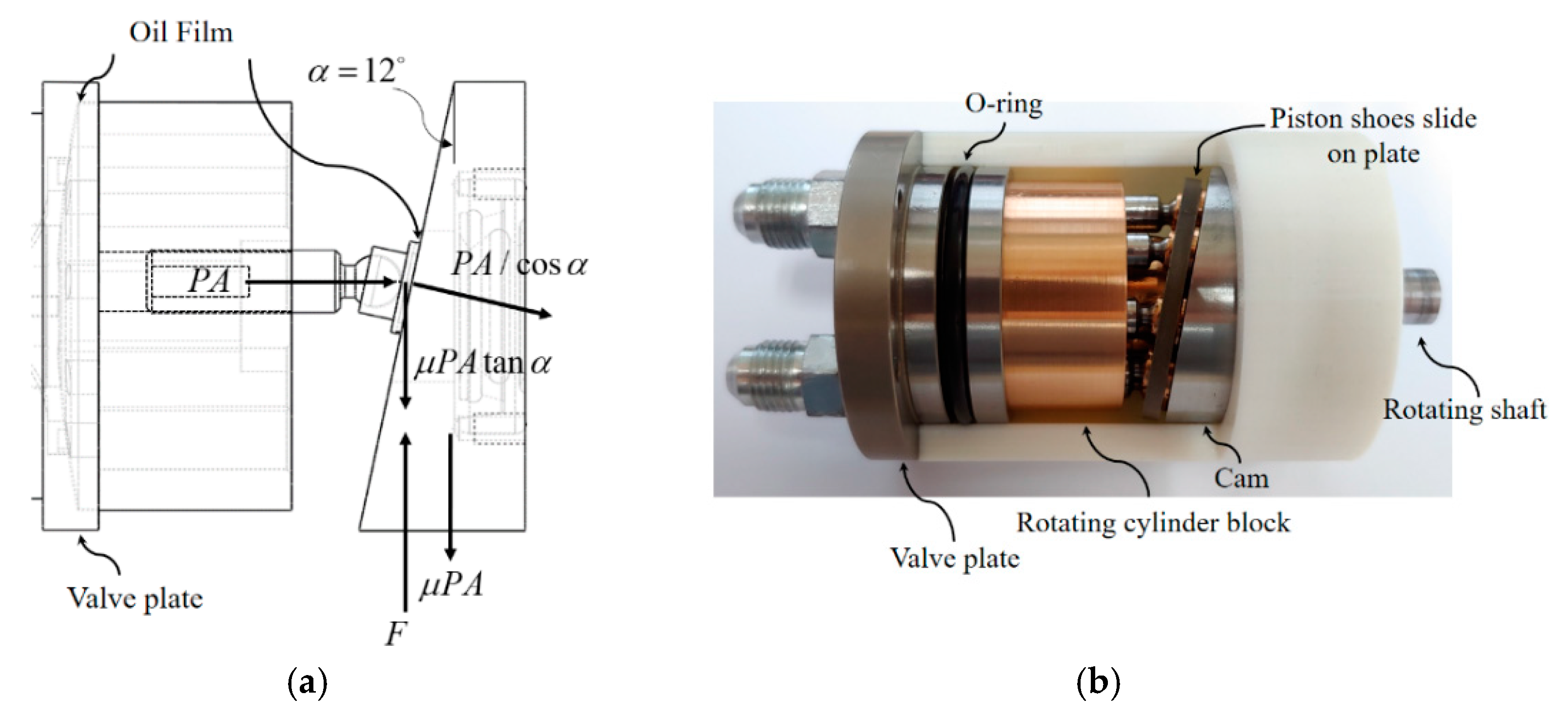
2.2. Design of the Piston Pump
The EHA system for an exoskeleton robot is composed of a motor, a hydraulic pump, a hydraulic cylinder, an oil tank, and a hydraulic circuit (hydraulic lines, hydraulic valves, etc.). Depending on the performance of the hydraulic pump, the operation of the robot is affected seriously. In this study, the hydraulic pump is a bidirectional swash plate piston pump, and it is designed based on the required flow rate according to the wearer’s gait cycle. Piston pump has excellent characteristics in the high-pressure region and is suitable for high-speed rotation. This is widely used in hydraulic systems that can vary the output capacity and produce high power [23]. Piston pumps are also divided into swash plate type axial pumps and bent axis type axial pumps, according to the field of use. Therefore, it is applied in various fields and researched and developed [24,25]. Such a piston pump can overcome the limitations of the gear pump. However, piston pump is complex and has many components. First of all, we developed a piston pump to compensate for the disadvantage of the existing piston pump and to apply it to the exoskeleton robot and the EHA system. The pump was compacted by integrating the pump housing and valve plate, and was simplified by integrating the cylinder block, spherical washer, and spline connection. The structure of the piston pump is shown in Figure 5, and the diameter and length are 56 mm and 81 mm, respectively. The hydraulic pump mainly consists of a drive shaft, a valve plate, a cylinder block, pistons, piston shoes, and a swash plate. The swash plate is at a 12 degree fixed angle. The nine holes in the cylinder block are formed at angles of 40 degrees. Through Equations (1) and (2), the stroke distance of the piston was designed to be 6.38 mm, and the displacement volume was about 1.5 cc.
The suction and discharge of the hydraulic pump change according to the rotation direction of the motor. First, when the motor rotates the drive shaft of the pump, the cylinder block connected to the drive shaft rotates. At this time, the piston shoe connected to the piston and ball socket joint moves along the surface of the cam, and the piston moves up and down in the cylinder block. As a result, the hydraulic pressure is produced, and then the pump starts sucking and discharging the hydraulic fluids. Because the valve plate and the cylinder block rotate in surface contact, they are made of different materials in consideration of friction. The cylinder block is made of brass and the valve plate is made of iron. Furthermore, when the piston pushes the hydraulic fluids, the oil film is formed between the cylinder block and the valve plate, so that the cylinder block gently rotates. For the same reason, the piston was made of brass, and the hole was made in the piston and shoe to produce an oil film. The valve plate and the cylinder block contact each other, and the pistons with shoes and the cam are shown in Figure 6b (the inside of the proposed pump).
Figure 6.
An oil film is formed on the surface where the respective parts are in contact with each other. (a) This is a side view of the pump, and (b) this is the inside view of the proposed pump.
When the exoskeleton robot supports a mass of 40 kg, the internal pressure of the cylinder becomes 12.73 . At this time, the force F on one piston can be obtained as follows:
The piston area A is , and the cam angle is 12 degrees. Assuming that the friction coefficient between brass and iron is 0.06, the force is
In order to produce the above pressure, the piston must push the hydraulic fluids by the force F. The rotation radius of the piston r is 15 mm, and 9 pistons are operated, but half of the pistons are sucked and half are discharged simultaneously. Therefore, the required torque is 608 mNm. For this purpose, the Maxon 400 Watt, EC60 BLDC motor was selected for the pump motor. The specifications of the desired pump and the motor are shown in Table 2.
Table 2.
The specifications of the desired pump and the motor.
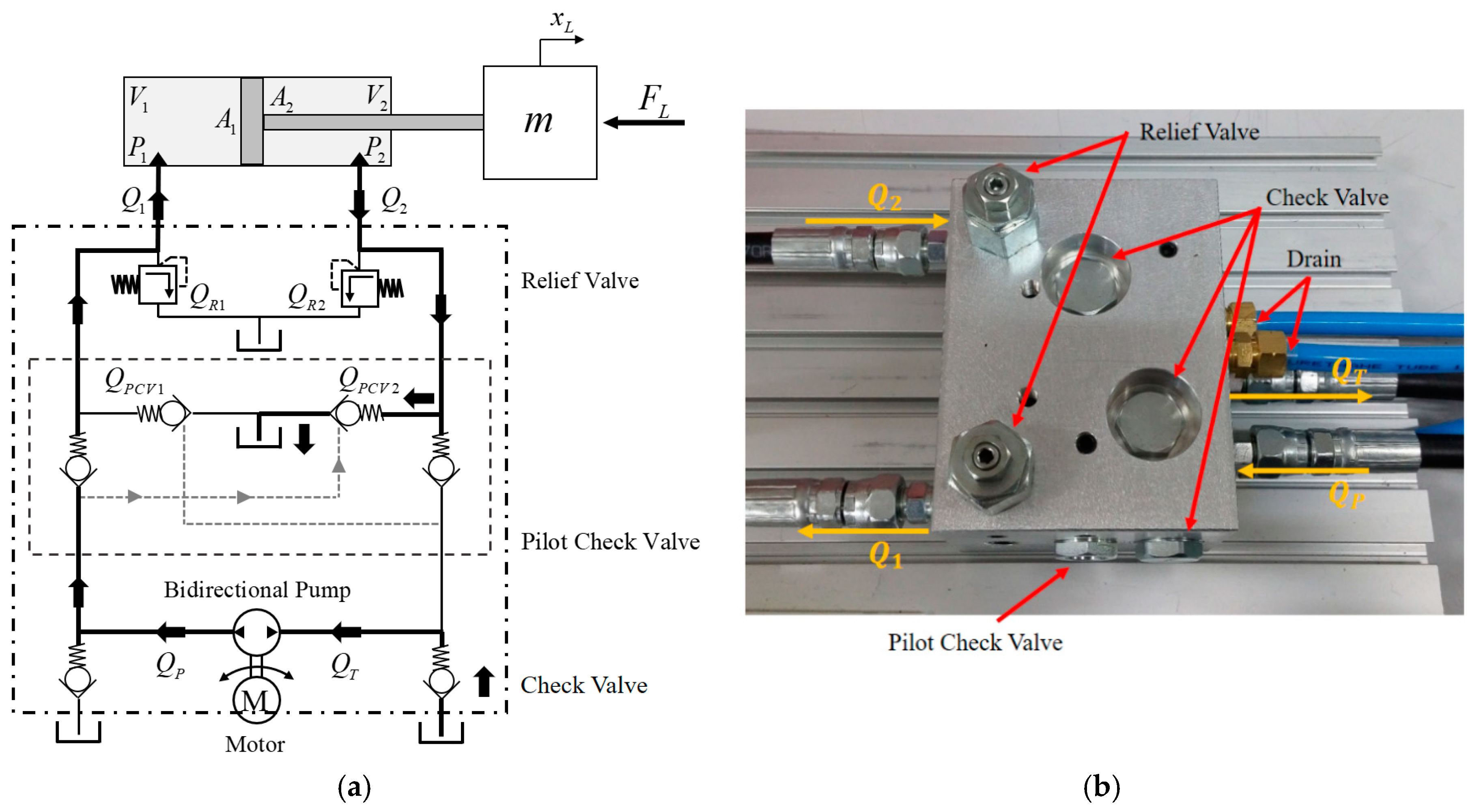
3. Design of the Hydraulic Circuit
A hydraulic system considering a hydraulic exoskeleton robot mostly uses a unidirectional pump. This system needs a relief valve, a check valve, a pilot check valve, and a hydraulic cylinder. Because the pump is unidirectional, it needs an additional servo valve for the cylinder to change direction. So, the operation of the exoskeleton robots using the hydraulic system is divided into the active mode and the passive mode. In other words, because it is a semi-active hydraulic system, the pump rotates unidirectionally and the cylinder advances to lift the weight. However, in order for the cylinder to move backward, the flow control valve is opened to move the cylinder backward by the force of the wearer [12]. In other words, when the robot performs the sit-to-stand operation, the robot increases the strength of the wearer via the actuator. Conversely, for the stand-to-sit operation in swing phase, the actuator moves manually. The cylinder moves backward through the directional control valve while the motor continues to operate [13]. In this case, the system becomes complicated, the efficiency becomes low, and it has problems with noise, vibration, and leakage. In order to overcome these drawbacks, we developed a bidirectional pump that is applicable to the hydraulic exoskeleton robot, and we also designed a hydraulic circuit.
Figure 7a shows the designed hydraulic circuit. The circuit consists of the bidirectional pump, two pilot-operated check valves, four check valves, two relief valves, and the oil tank. and are the actual flow rates flowing in and out of the cylinder. and are drained through the relief valve. For system safety, the relief valve is set so that the internal pressure does not exceed 25 bar. When a motor rotates, the pump produces pressure and the cylinder moves forward. and are sucked through the pump from the tank, and unlike the double-rod cylinder, the cross-sectional areas and in the single-rod cylinder are different. So, the flow rates and are different. The pilot-operated check valve compensates for this difference in flow, allowing the cylinder to move gently [26]. The pressure operates the pilot-operated check valve on the line, which results in being equal to and flowing into the tank. There are also check valves between the cylinder and the pump, so that the flow from the cylinder does not directly enter the pump. By designing the hydraulic circuit in this way, the hydraulic fluids circulate in the system but can be viewed as an open circuit. So, the mathematical modeling is simplified. Also, if the motor is not driven, the pilot-operated check valve is not opened, and the cylinder can maintain a constant force because of the check valve. Figure 7b shows the actual hydraulic circuit; the circuit was modularized with a compact size of . Because of this, the hydraulic hose between the valves was eliminated. So, the circuit has been simplified, and maintenance of leaks has become easier. The oil tank was made of acrylic, and its size is . The cylinder’s maximum pressure was 3.5 MPa, the inner diameter was 20 mm, and the stroke length was 120 mm.
Figure 7.
The hydraulic fluids circulate in the system: (a) is the proposed hydraulic circuit, and (b) is a manifold of the hydraulic circuit.
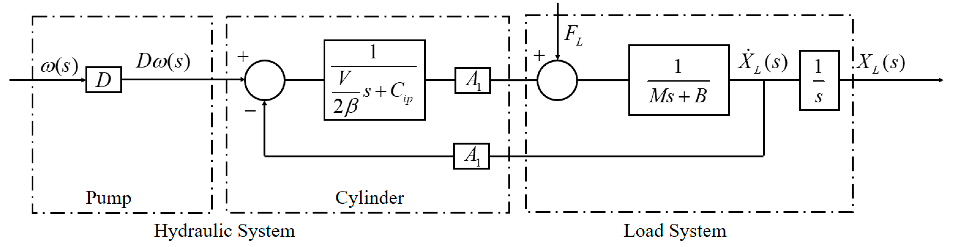
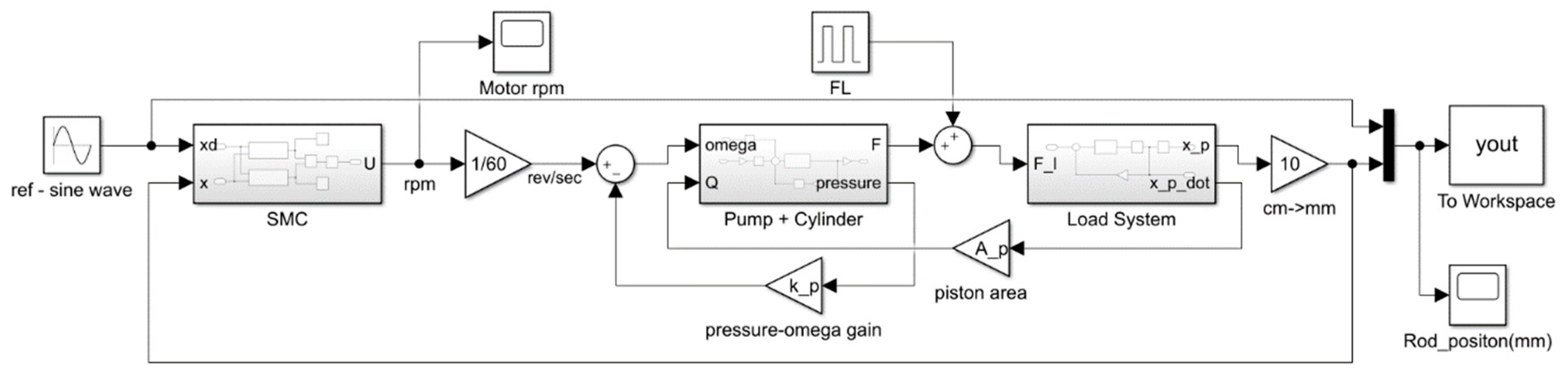
4. Modeling of the EHA System
By setting each chamber of the single rod hydraulic cylinder to the control volume and applying the continuity equation for the pressure change, it is derived as follows [27]:
and are the cylinder volumes, and are the cylinder pressures, is the internal leakage coefficient of the piston, and is the external leakage coefficient of the piston. is the effective bulk modulus of the hydraulic fluid. After rewriting Equation (10) with respect to the change in pressure and arranging it, it is the same as Equation (11):
The volumes and of both chambers of the cylinder can be expressed as Equation (12) with respect to the initial volume:
when the cylinder moves forward, that is, when the electric motor rotates forward, the total flow rate of the hydraulic circuit can be expressed as follows:
In practice, the relief valves were not considered in this model, because they are safety devices and stay below the valve set during operation of the EHA system. So, . Additionally, can be expressed as . is the displacement of the pump, is the motor speed, and is the leakage coefficient of the pump.
The flow rate through the pilot-operated check valve is expressed as shown in Equation (15), and the flow rate varies depending on the area . As a result, the pressure–flow rate equation for the hydraulic circuit becomes a nonlinear function. The flow rate is determined according to the following equation [28]:
where
is the flow discharge coefficient, is the instantaneous orifice passage area, is the closed valve leakage area, is the fully open valve passage area, is the minimum pressure for turbulent flow, is the equivalent pressure differential across the control member, is the valve cracking pressure, and is the pressure needed to fully open the valve.
Using the above Equations (12) and (13) and the Laplace transform, we can obtain Equation (16):
when the left chamber in the single rod is equal to the right chamber, is the total volume and the volume is .
By referencing the hydraulic circuit of the EHA system shown in Figure 7, the equation of motion of the load system can be described as
when the cylinder moves forward, the pilot-operated check valve on the opposite side is opened by the pressure . Because the flow rate is drained into the tank, we do not need to consider pressure . Assuming that there is no disturbance, Equation (17) is rearranged by the Laplace transform and Equation (18) is obtained as:
After arranging Equation (16) to determine the pressure and substituting it in Equation (18), the transfer function for the entire system can be determined, as shown in Equation (19). The block diagram is shown in Figure 8:
Figure 8.
The block diagram of the entire system.
The hydraulic system has nonlinearity, as shown in Equations (10) and (15). Also, the temperature of the hydraulic fluid changes because of the friction and pressure acting on the hydraulic cylinder and the hydraulic pump. Nonlinearity occurs because of the uncertainty of the modeling, the viscosity change, and the leakage. So, the EHA system must be robustly controlled against these nonlinearities and uncertainties [26,29].
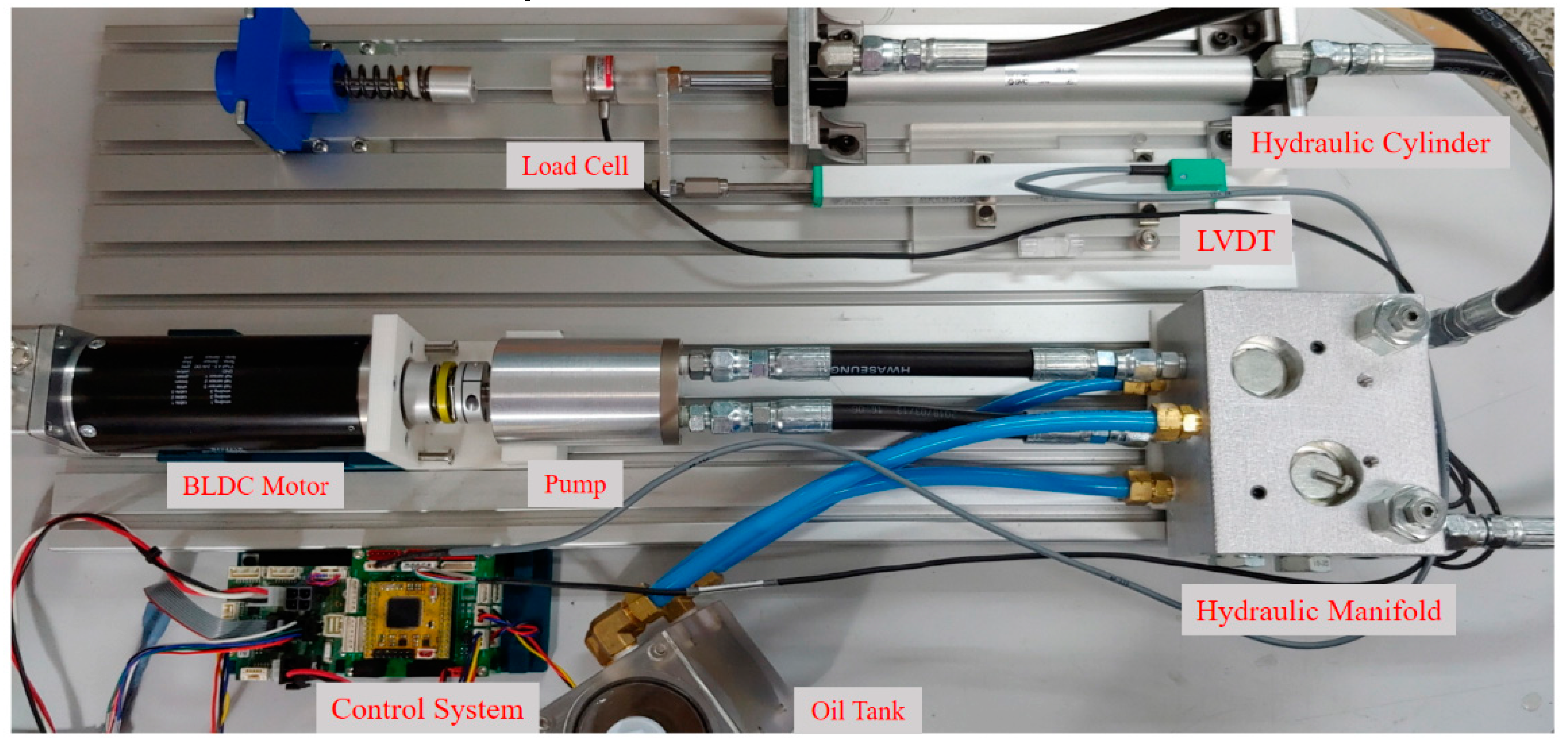
5. The Position and Force Control Experiments
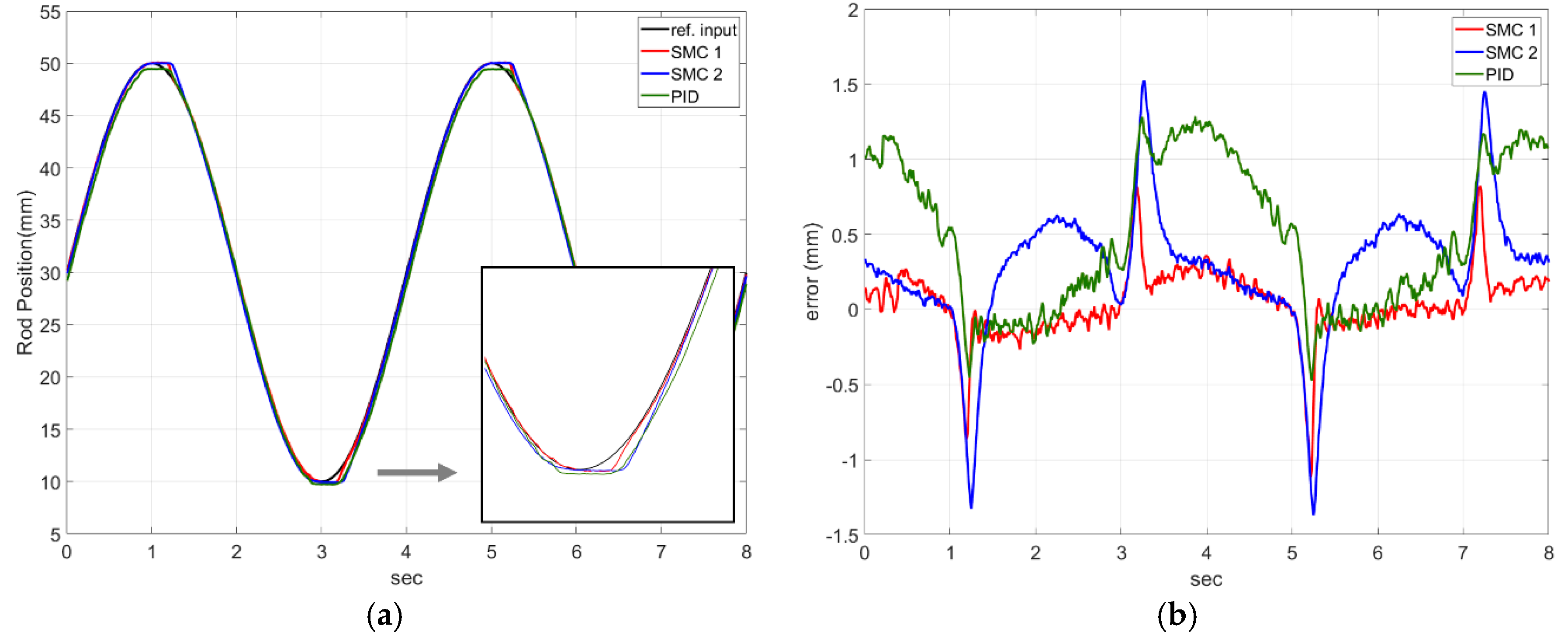
5.1. Design of the Sliding Mode Control
In order to apply a sliding mode control to the EHA system, the nonlinear dynamic system is defined as follows:
where the scalar is the output of interest, the scalar u is the control input, and is the state vector. One of the typical methods for a nonlinear system is sliding mode control. First, a sliding surface is defined, and the state () slides along the surface of the desired state (). Once on the sliding surface, s (t) = 0 is satisfied and the desired state is maintained.
For the nonlinear control of the EHA system, the sliding surface can be defined as [30]:
where, is the tracking error, and and are the positive constants. In this study, because the position, velocity, and acceleration of the single rod of the EHA system should be tracked, is set to 3, and the sliding surface is defined as follows:
For to occur, the Lyapunov function is set to , and when , the current state does not deviate from the sliding surface. The control input consists of the equivalent control input for entering the sliding surface and the switching control input for not going out of the surface at the sliding surface (). However, the function , which is the nonlinear function, generates chattering because of the discontinuous response. To avoid this, we replaced it with a saturation function. So, the control input is
Assuming that the cylinder rod moves forward, the equation differentiating Equation (16) can be rearranged with respect to time for x as follows:
By substituting Equation (13) in Equation (24), we can obtain Equation (25):
If in this equation is replaced by , and summarized as , then the equation is as follows:
where, includes the disturbance , volumetric elastic modulus, area, volume, and so on.
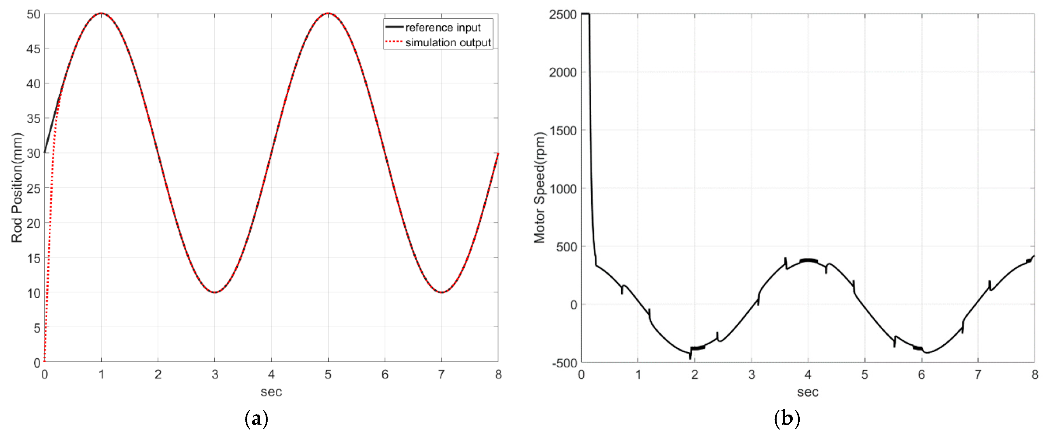
5.2. Experiment Configuration and Control Experiments
This chapter explains the experiment configuration and control experiments. The experiment configuration consisted of the hydraulic pump, the manifold of the hydraulic circuit, a double acting single rod cylinder, a linear variable differential transformer (LVDT), a load cell, a motor driver, and an embedded system for control and data acquisition. The experimental setup is shown in Figure 9. The embedded system consisted of the control board and the data acquisition board. Each board was equipped with controller area network (CAN) communication, the serial peripheral interface (SPI) communication, amplifier, analog filter, and the 200 MHz microcontroller unit (MCU). The single rod cylinder for the experiment had a 120 mm stroke length. The inner diameter was 20 mm, and the rod diameter was 10 mm. The LVDT, which measures the position of the cylinder rod, had a stroke length of 150 mm. The load cell that measures the reaction force of the cylinder could measure up to 100 kg and was installed at the end of the cylinder.
Figure 9.
All experiments used a load cell, hydraulic cylinder, motor, pump, manifold, and control system.
Meanwhile, when the exoskeleton robot operates in the stance phase, the robot performs position control, and when operating in the swing phase, the robot grasps the wearer’s intention and performs force control. And speed control loop is generally contained within the position control loop. So, the verification of the hydraulic pump and the hydraulic circuit were performed through position and force tracking. Also, the designed sliding mode controller was verified in comparison with a proportional integral derivative (PID) controller.
The reference input for tracking of the position was a sine wave, and the PID control and sliding mode control were compared through experiments. First, we simulated them with Matlab Simulink, as shown in Figure 10, and the results are shown in Figure 11. Table 3 shows the parameters of the cylinder and pump, and Table 4 shows the PID control and sliding mode control parameter values for each experiment.
Figure 10.
Control simulation with Matlab Simulink.
Figure 11.
Simulation result of the sliding mode control scheme: (a) is the result of position performance, and (b) is the speed of the motor.
Table 3.
The parameters of the cylinder and pump.
Table 4.
The parameters of the control for each experiment.
As shown in Figure 11a, we can see that the cylinder followed the sine wave well. Figure 11b shows the speed of the motor. Because the initial position of the cylinder was 0 mm, the initial rpm of the motor was too large to follow the reference input. After the current state reached the sliding surface, we can see that control value switched in succession for continuous tracking.
Figure 12 gives a comparison of the SMC (sliding mode control) and the PID control for the experimental equipment. In the simulation, the position reference input value was the sine wave. At this time, the control period was set to 10 ms. As in the simulation, and were set to be the same, and in Figure 12a, SMC 1 was set to and , SMC 2 was set to and , and PID was set to , , and . This shows that the error increased at 1 s and 5 s for all three controls. This is because the moving distance of the cylinder per time was short and the resolution () of the LVDT with the stroke length of 120 mm was low. In other words, the LVDT error occurred because of the characteristics of the analog system (system noise and the measurement noise), which increased the rate of change in a very short time. Thus, the control response was a little slow, and the position tracking was not good at 1, 3, and 5 s. To improve the control performance, it would be better to use high-resolution LVDT or to increase the control period of the system.
Figure 12.
Comparisons of the experimental results: (a) is the position control performance of the SMC (sliding motor control) and the PID control, (b) is a comparison of errors.
On the other hand, when the moving speed of the cylinder was high, this problem did not occur in the sliding mode control and PID control. However, PID had a larger error than sliding mode control when tracking the position (Figure 12b). The PID controls showed good follow-up, but it is unstable and slower than the designed SMC 1. In case of PID control, the error value has some positive offset in 0–1 s, 3–5 s, and 7–8 s intervals. This is because the applied cylinder is a single rod, not a double rod. In other words, because the volumes of both chambers are different, when the same amount of flow rate flows into the cylinder, a speed difference of the forward and backward movement of the rod occurs. In order to follow the sine wave, the motor must rotate at high speed in a section of 0–1, 3–5, 7–8 s. At this time, the limit of the PID controller was shown in this section. In terms of the performance of the controllers, SMC 1 was more accurate than SMC 2 in terms of following the desired input into the sliding surface. When the state variables enter the sliding surface, the control input is switched to the magnitude of . If the larger disturbance enters the system, it is temporarily outside of the surface boundary. Theoretically, a larger value can be given to prevent this, but when applied to the actual system, a large vibration is generated. In the experiment, the average error of SMC 1 was 0.16 mm, which is a satisfactory value for a practical system.
Figure 13 shows the results of the cylinder tracking the desired force through the sliding mode control and the PID control. The cylinder followed forces of 60, 90, and 120 N at 2 s intervals. As shown in Figure 13a, SMC 1 was set to and , SMC 2 was set to and , and SMC 3 was set to and . Overshoot occurred in the system at , and the system became unstable. Also, chattering occurred when even with the same value. Therefore, the cylinder was most stable when and (SMC 2). Figure 13b shows a comparison between SMC 2 and the PID1,2 control. The PID control showed good follow-up but was unstable and less accurate than the designed SMC 2.
Figure 13.
Comparisons of the experimental results: (a) is the force control performance of SMC, and (b) is a comparison of SMC and PID control.
6. Discussion
In this study, we developed the EHA system which combines the advantages of hydraulic actuators and electric actuators. The pump design of the EHA system was determined through human gait analysis and design of an exoskeleton robot. In addition, the number of pistons was set to nine, in consideration of the pulsation rate and pump size. At this time, the pump was designed and manufactured by a bidirectional swash piston pump. In addition, several valves were made into one manifold, and the circuit was simplified to make it smaller and lighter. The controller was designed based on the mathematical modeling of the EHA system. Because hydraulic systems have nonlinearity and system uncertainty characteristics, the sliding mode controller was designed. We verified the performance of the developed EHA system through position and force control. So, in this study, the control parameters were set to and in order to enter the sliding surface when tracking the position with respect to the sine wave. To track the desired force, the control parameters were set to and . It can be seen that the overshoot occurs as the control parameter increases in each control experiment. As is larger, state variable does not deviate the sliding surface, but the system becomes unstable. Rather than enlarging the control parameters for the fast response of the system, it should be determined considering the stability of the system. Furthermore, compared with the PID control, we found that the sliding mode control performed better in a nonlinear system. The EHA was operated by controlling the speed and force of the cylinder. When the actual cylinder is not moving, the motor is not driven and the forward and backward movement of the cylinder is controlled by the rotation of the motor. This exoskeleton robot with a conventional unidirectional pump can increase the efficiency by overcoming the disadvantage that the motor must continue to operate regardless of the operation of the cylinder. In addition, when the knee joint of the robot is bent in the swing phase, it is possible to reduce the burden on the wearer by driving the motor instead of the wearer’s force. The hydraulic circuit was designed with consideration of the walking operation of the robot and compacted by integrating them. Therefore, the proposed EHA system applied to the exoskeleton robot can solve the disadvantages of the existing robot which is used by a conventional unidirectional pump. The design and control of the exoskeleton robot to which this system is applied should be continuously researched.
Author Contributions
D.L. designed the pump, EHA system, and controller, and wrote the paper; D.L. and B.S. contributed to conceptualization, and performed the experiments; B.S. and S.Y.P. analyzed the data and reviewed and edited the paper; Y.S.B. contributed funding acquisition and project administration.
Funding
This research was supported by the Basic Science Research Program grant funded by the National Research Foundation of Korea (NRF) (No. 2017R1A2B4009265).
Conflicts of Interest
The authors declare no conflict of interest.
References
- Farris, R.J.; Quintero, H.A.; Goldfarb, M. Preliminary Evaluation of a Powered Lower Limb Orthosis to Aid Walking in Paraplegic Individuals. IEEE Trans. Neural Syst. Rehabil. Eng. 2011, 19, 652–659. [Google Scholar] [CrossRef] [PubMed]
- Zeilig, G.; Weingarden, H.; Zwecker, M.; Dudkiewicz, I.; Bloch, A.; Esquenazi, A. Safety and tolerance of the ReWalk™ exoskeleton suit for ambulation by people with complete spinal cord injury: A pilot study. J. Spinal Cord Med. 2012, 35, 96–101. [Google Scholar] [CrossRef] [PubMed]
- Ikeuchi, Y.; Ashihara, J.; Hiki, Y.; Kudoh, H.; Noda, T. Walking assist device with bodyweight support system. In Proceedings of the 2009 IEEE/RSJ International Conference on Intelligent Robots and Systems, St. Louis, MO, USA, 10–15 October 2009; pp. 4073–4079. [Google Scholar]
- Hassan, M.; Kadone, H.; Suzuki, K.; Sankai, Y. Exoskeleton robot control based on cane and body joint synergies. In Proceedings of the 2012 IEEE/RSJ International Conference on Intelligent Robots and Systems (IROS), Vilamoura, Algarve, Portugal, 7–12 October 2012; pp. 1609–1614. [Google Scholar]
- Young, A.J.; Ferris, D.P. State of the Art and Future Directions for Lower Limb Robotic Exoskeletons. IEEE Trans. Neural Syst. Rehabil. Eng. 2017, 25, 171–182. [Google Scholar] [CrossRef] [PubMed]
- Kawamoto, H.; Sankai, Y. Power assist method based on Phase Sequence and muscle force condition for HAL. Adv. Robot. 2005, 19, 717–734. [Google Scholar] [CrossRef]
- Yu, S.N.; Lee, H.D.; Lee, S.H.; Kim, W.S.; Han, J.S.; Han, C.S. Design of an under-actuated exoskeleton system for walking assist while load carrying. Adv. Robot. 2012, 26, 561–580. [Google Scholar] [CrossRef]
- Huo, W.; Mohammed, S.; Moreno, J.C.; Amirat, Y. Lower Limb Wearable Robots for Assistance and Rehabilitation: A State of the Art. IEEE Syst. J. 2014, 10, 1068–1081. [Google Scholar] [CrossRef]
- Lee, S.J.; Oh, J.W.; Lee, Y.K.; Choi, J.H. Development of Micro Hydraulic Actuator for force assistive wearable robot. In Proceedings of the IEEE ISR 2013, Seoul, South Korea, 24–26 October 2013. [Google Scholar]
- Bechet, F.; Ohnishi, K. Electro-hydraulic force transmission for rehabilitation exoskeleton robot. In Proceedings of the AMC2014-Yokohama, Yokohama, Japan, 14–16 March 2014; pp. 260–265. [Google Scholar]
- Amundson, K.; Raade, J.; Harding, N.; Kazerooni, H. Development of Hybrid Hydraulic-Electric Power Units for Field and Service Robots. Adv. Robot. 2006, 20, 1015–1034. [Google Scholar] [CrossRef][Green Version]
- Kim, H.-G.; Lee, J.-W.; Jang, J.; Park, S.; Han, C. Design of an exoskeleton with minimized energy consumption based on using elastic and dissipative elements. Int. J. Control Autom. Syst. 2015, 13, 463–474. [Google Scholar] [CrossRef]
- Kim, H.; Shin, Y.J.; Kim, J. Design and locomotion control of a hydraulic lower extremity exoskeleton for mobility augmentation. Mechatronics 2017, 46, 32–45. [Google Scholar] [CrossRef]
- Zhu, J.; Wang, Y.; Jiang, J.; Sun, B.; Cao, H. Unidirectional variable stiffness hydraulic actuator for load-carrying knee exoskeleton. Int. J. Adv. Robot. Syst. 2017, 14, 1–12. [Google Scholar] [CrossRef]
- Lee, W.Y.; Kim, M.J.; Chung, W.K. An approach to development of electro hydrostatic actuator (EHA)-based robot joints. In Proceedings of the 2015 IEEE International Conference on Industrial Technology (ICIT), Seville, Spain, 17–19 March 2015; pp. 99–106. [Google Scholar]
- Kazerooni, H. Exoskeletons for human power augmentation. In Proceedings of the 2005 IEEE/RSJ International Conference on Intelligent Robots and Systems, Edmonton, AB, Canada, 2–6 August 2005; pp. 3459–3464. [Google Scholar]
- Zoss, A.B.; Kazerooni, H.; Chu, A. Biomechanical design of the Berkeley lower extremity exoskeleton (BLEEX). IEEE/ASME Trans. Mechatron. 2006, 11, 128–138. [Google Scholar] [CrossRef]
- Habibi, S.; Goldenberg, A. Design of a New High Performance ElectroHydraulic Actuator. In Proceedings of the International Conference on Advanced Intelligent Mechatronics Proceedings, Atlanta, GA, USA, 19–23 September 1999; Volume 9, pp. 227–232. [Google Scholar]
- Kou, F.; Wang, Z.; Du, J.; Li, D.; Fan, E. Study on force tracking control of electro-hydraulic active suspension. In Proceedings of the 2017 IEEE 3rd Information Technology and Mechatronics Engineering Conference (ITOEC), Chongqing, China, 3–5 October 2017; pp. 1078–1082. [Google Scholar]
- Gaile, A.; Lue, Y. Electro Hydraulic Actuation (EHA) systems for primary flight control, landing gear and other type of actuation. In Proceedings of the International 2016 IEEE International Conference on Aircraft Utility Systems (AUS), Beijing, China, 10–12 October 2016; pp. 723–728. [Google Scholar]
- Rose, J.; Gamble, J.G. HumanWalking, 2nd ed.; Williams & Wilkins: Baltimore, MD, USA, 1994. [Google Scholar]
- Cho, S.H.; Park, J.M.; Kwon, O.Y. Gender differences in three dimensional gait analysis data from 98 healthy Korean adults. Clin. Biomech. 2004, 19, 145–152. [Google Scholar] [CrossRef] [PubMed]
- Kim, D.J. Hydraulic Engineering; Bookshill: Seoul, Korea, 2002. [Google Scholar]
- Guo, K.; Xu, Y.; Li, J. A Switched Controller Design for Supply Pressure Tracking of Variable Displacement Axial Piston Pumps. IEEE Access 2018, 6, 3932–3942. [Google Scholar] [CrossRef]
- Zhang, J.; Qun, C.H.A.O.; Bing, X.U. Analysis of the cylinder block tilting inertia moment and its effect on the performance of high-speed electro-hydrostatic actuator pumps of aircraft. Chin. J. Eronaut. 2018, 31, 169–177. [Google Scholar] [CrossRef]
- Ahn, K.K.; Nam, D.N.C.; Jin, M. Adaptive Backstepping Control of an Electrohydraulic Actuator. IEEE/ASME Trans. Mechatron. 2014, 19, 987–995. [Google Scholar] [CrossRef]
- Merritt, H.E. Hydraulic Control Systems; Wiley: New York, NY, USA, 1967. [Google Scholar]
- Mathworks. Available online: https://kr.mathworks.com/help/physmod/hydro/ref/pilotoperatedcheckvalve.html?s_tid=srchtitle (accessed on 18 June 2019).
- Yao, B.; Bu, F.; Reedy, J.; Chiu, G.T.C. Adaptive Robust Motion Control of Single-Rod Hydraulic Actuators: Theory and Experiments. In Proceedings of the American Control Conference, San Diego, CA, USA, 2–4 June 1999; pp. 759–763. [Google Scholar]
- Slotine, J.-J.E.; Li, W. Applied Nonliear Control; Prentice-Hall Publisher: Upper Saddle River, NJ, USA, 1991; pp. 277–294. [Google Scholar]
© 2019 by the authors. Licensee MDPI, Basel, Switzerland. This article is an open access article distributed under the terms and conditions of the Creative Commons Attribution (CC BY) license (http://creativecommons.org/licenses/by/4.0/).