Abstract
In order to reduce the driving voltage and gain better output characteristics of piezoelectric actuators, an eight-zonal piezoelectric tube-type threaded ultrasonic motor based on two second-order bending modes was analyzed using the method of finite element analysis (FEA), and a prototype was fabricated and experimentally studied in this research. This piezoelectric motor was designed to be excited by four electrical sources applied simultaneously to four groups of electrodes on the customized lead zirconate titanate (PZT) tubular stator (inside diameter 5.35 mm, outside diameter 6.35 mm, length 30 mm), with ±90° phase shifts between adjacent electrodes. Experimental results show that the threaded motor could output a stall force (stall force means the output pull or thrust force when the linear speed is set to be zero) of about 5.0 N and a linear velocity of 4.9 mm/s with no load at the driving voltage of 40 Vpp (Vpp means the peak-to-peak value of the voltage volts). This piezoelectric motor with a compact structure and screw drive mechanism shows relatively fine velocity controllability and has huge superiority in micro-positioning systems.
1. Introduction
Ultrasonic motors are novel energy-conversing devices based on the principles of an inverse piezoelectric effect, resonant displacement amplification, and friction drive effect [1,2,3]. Since the prototype of the first ultrasonic motor was reported in the 1970s, it has attracted extensive attention worldwide for the merits of high power density, fine positioning accuracy, power-off self-locking, quick response, free electromagnetic interference, light weight, compact structure, and so on [3,4,5]. Based on the research so far, ultrasonic motors have been successfully applied in some commercial products in the fields of precise positioning, biomedical instruments, aeronautics and astronautics, and so forth [3,6,7,8].
In view of the different vibration waveform combinations for generating periodic rotary or linear movement, ultrasonic motors can be classified into three categories: traveling-wave type, standing-wave type, and composite type [9]. However, for the purpose of high torque output, a cylindrical traveling-wave type motor might be superior to flat ones in millimeter- and sub-millimeter-order diameters [10]. In 2000, Morita et al. [11] proposed a cylindrical miniature ultrasonic motor (Ø1.4 mm × 5 mm) based on a lead zirconate titanate (PZT) thin film (0.25 mm). However, the maximum rotary speed and torque were only 680 rpm and 0.67 μNm at 20 Vpp driving voltage due to the thin-film deposition structure. In 2002, Koc et al. [12] fabricated a cylindrical-type ultrasonic motor (Ø2.4 mm × 10 mm), which consisted of a metal tube and two piezoelectric plates bonded on its surface, based on two first-order bending modes. The maximum output torque was up to 1.8 mNm at 120 Vpp driving voltage. In addition, in 2006, Kanda et al. [13] proposed a cylindrical rotary motor based on a PZT tube stator that was divided into four exciting electrode parts. Then, in 2014, Wang et al. [14] fabricated a screw-thread-type ultrasonic actuator based on a Langevin piezoelectric vibrator. At 300 Vpp, the maximum thrust force, velocity, and efficiency were approximately 4.2 N, 9.5 mm/s, and 5.6%, respectively. Later, in 2016, Chang et al. [15] reported a single-phase driven screw-thread-type cylindrical ultrasonic motor based on an asymmetric stator design and piezoelectric plate bonding structure. When the driving voltage was 200 Vpp, the maximum no-load velocity was 4.1 mm/s and the stall force was 1.6 N. The cylindrical traveling-wave-type motor has been studied for decades, and various tube-shaped piezoelectric motors based on the first-order bending modes [16,17] have been proposed and experimentally researched. However, few researchers have dealt with the coupling of high-order bending modes.
In this study, we proposed an eight-zonal piezoelectric tube-type threaded ultrasonic motor based on two second-order bending modes. Experimental results show that the threaded motor could output a stall force of about 5.0 N and a linear velocity of 4.9 mm/s with no load at the driving voltage of 40 Vpp, thus, realizing the purpose of reducing the driving voltage and improving the output performance.
2. Structure, Design Principle, and Working Mechanism
2.1. Structure of the Threaded Actuator
The structure of the piezoelectric tube-type threaded ultrasonic motor we proposed is illustrated in Figure 1a. A fabricated prototype is shown in Figure 1b. The motor is combined with a customized piezoelectric ceramic tube (from PI Co., Ltd, Germany) acting as a stator, two nuts (outer diameter 6.35 mm, inner diameter 3 mm, length 1.5 mm), and a precise screw rod (diameter 3 mm, length 50 mm) acting as a rotor. The nut is screwed with the precise screw rod through the internal thread. The stator is composed of a piezoelectric ceramic tube and two nuts bonded with both ends. The dimension of the customized piezoelectric ceramic tube is Ф6.35 × Ф5.35 × 30 mm. The inner and outer surfaces of the tube are both plated with silver electrodes, but the electrode on the outer surface is divided into eight parts as shown in Figure 1a to excite two second-order bending (B2) modes, which could then be used to produce a “hula hoop” wobbling motion [10]. Finally, through the thread drive mechanism, the motor directly transforms the wobbling motion of the stator into linear movement along the screw rod without additional mechanical conversion.
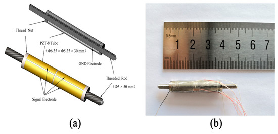
Figure 1.
(a) Structure of the threaded motor. (b) Photo of the fabricated motor.
2.2. Design Principle of the Threaded Actuator
Figure 2 shows the schematic diagram of the vibration mode for first-order and second-order free-free bending modes. We can see from the curves that if the stator works in first-order bending vibration mode, there would be two nodal points (nodal point means its displacement during the entire vibration period remains to be zero) in the axial direction: 0.22 and 0.78. These two nodal points were designed to be in the clamp position. However, the clamp device would definitely affect the pattern of the surface electrodes and, thus, decrease the performance of the piezoelectric motor. As for the second-order bending mode, there were three nodal points in the axial direction: 0.13, 0.50, and 0.87. The middle nodal point 0.5 is appropriate for clamping because it is easy to locate and the middle part is just the truncating boundary to divide the surface electrode for second-order bending mode excitation, which is illustrated in detail in the following part.
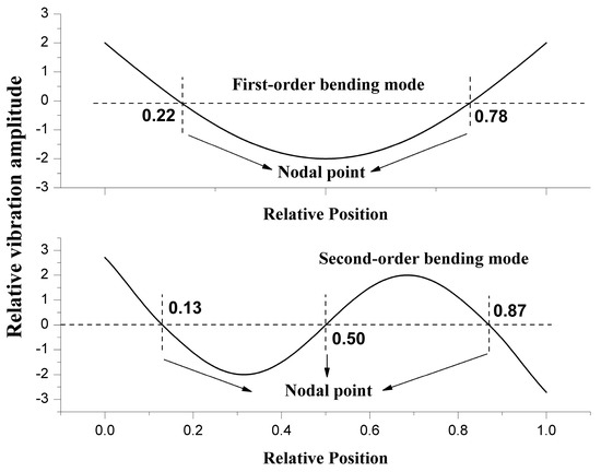
Figure 2.
Schematic diagram of vibration mode for first-order and second-order free-free bending modes.
As shown in Figure 3, within the entire length range of the stator, the mid-point l/2 is considered as the cut-off point, where it is one of the second-order bending vibration nodal points. The left and right sides of the strain curve have negative and positive values, respectively. Thus, the deformation states on both sides of the mid-point are opposite during the vibration period. If the traditional four-zone mode is continued to be used for electric excitation, the electric exciting state of any electrode area along the axial direction is completely the same, which leads to the inconsistency between the theoretical bending vibration deformation and the deformation caused by the actual electric exciting mode, and the expected second-order bending vibration cannot be realized. Therefore, the electrodes on the outer surface of the piezoelectric tube must be truncated along the circumference of the midpoint to form eight uniform zones.
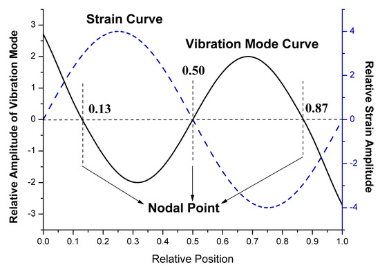
Figure 3.
Schematic diagram of vibration mode and strain curve for second-order bending mode.
Figure 4a demonstrates how the outer electrode surface of the piezoelectric ceramic tube is divided into eight parts, as well as the polarization direction of each part. This piezoelectric motor was designed to be excited by four electrical sources applied to four groups of electrodes on the customized piezoelectric tubular stator simultaneously, with ±90° phase shifts between adjacent electrodes for the left and right circumference parts, as shown in Figure 4b.
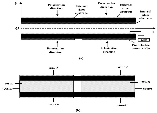
Figure 4.
(a) Partition pattern of the piezoelectric ceramic tube for second-order bending vibration; (b) Electrical signal supply mode for the piezoelectric ceramic tube.
2.3. Working Mechanism
The eight-zonal stator was designed and then optimized with the finite element analysis (FEA) method by using ANSYS Mechanical APDL 15.0. To observe the movement, a time-dependent analysis was performed with an input voltage of 50 V at its resonant frequency as shown in Figure 4b. A random point at the helical portion of the nut, whose three-dimensional trajectory is shown in Figure 5, was selected. The displacement of the Z component (axial direction) was much larger than the other two components, as demonstrated by the projection on each plane. Thus, the simulation result shows that the designed stator can achieve fine elliptic curve motion to produce a “hula hoop” wobbling movement.
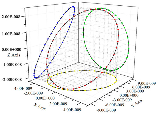
Figure 5.
Three-dimensional trajectory of a random point at the helical portion of the nut.
In 1998, Wallaschek [18] theoretically analyzed the mechanical properties of the friction contact surfaces of the ultrasonic motor. According to his theory, we established a friction model for thread contact surface, and the threaded driving mechanism is discussed in Figure 6. Compared to the thread angle α of a triangular thread in Figure 6a, the helix angle of the threads is very small and can be ignored. If there is no deformation at the contact surface, then the contact point is the peak of the elliptical motion curve. The considerable displacement of the Z component results in an included angle (β in the figure) between the plane where the elliptical motion lies and the XOY plane. When traveling waves are excited in the stator, the rotor would be driven at the peak of the elliptical motion curve by the frictional force. When the rotor is applied with an axial preload Fa, the maximum load force output T can be calculated by Equation (1):
where Fs is the maximum static friction, and μ is the coefficient of static friction at the contact surface.
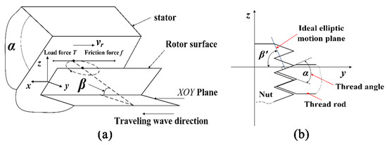
Figure 6.
Driving mechanism at the contact surface between the rotor and stator. (a) Front view. (b) Vertical section view.
Moreover, as shown in Figure 6b, the ideal elliptic motion plane should be perpendicular to the contact surface. Thus, the contact area at the helical portion would produce a speed of vr along the tangential direction of the contact surface. The relationship between the ideal included angle (β’ in the figure, between the ideal elliptical motion plane and the XOY plane) and the thread angle α can be illustrated as Equation (2):
α = π − 2β’
However, if the real included angle β is not equal to the ideal included angle β’ when the traveling wave is generated, there would be a radial component in the perpendicular direction of the moving speed vr in the contact plane. This radial component would bring about a slip phenomenon in the contact plane, causing problems like movement instability and energy loss, and, thus, decreasing the output performance of the motor.
In addition, from Equation (1), we can see that a smaller thread angle α would contribute to a larger output load force; from Equation (2), a smaller thread angle α demands a larger ideal included angle β’, which means larger displacement of the Z component in the elliptical trajectory. Finally, combining the theoretical and FEA analysis above and the machining difficulty, we chose 30° for the thread angle α for relatively fine performance.
By means of thread drive, the wobbling motion of the stator can be converted into linear motion along the axis without any additional mechanical conversion. Besides, the threads improve the position resolution and reduce the linear speed, as well as provide a long stroke corresponding to the length direction of the screw rod. In addition, as with the other cylindrical-type piezoelectric motors [10,12,14], the movement direction of the motor we proposed can be easily reversed by changing the phase shifts of the electric signals on the four groups of electrodes from 90° to −90°.
3. Experiments and Results
3.1. Identification of the Ceramic Tube
Before fabricating the prototype, the cross-section morphology and the elemental composition of the customized piezoelectric tube were identified by a field emission scanning electron microscope (FESEM) (Gemini 2, Zeiss, Germany). As shown in Figure 7a, there were few defects such as pores, and the grains almost had a uniform diameter of about 2 μm. In Figure 7b and Table 1, the material of the ceramic tube was identified to be lead zirconate titanate (PZT). We made use of PZT-8, one type of PZT series material, because of its superior performance, such as high mechanical quality factor and relatively low dielectric loss. By conducting these two tests, the chemical and physical properties of the PZT-8 tube was proved to be almost isotropic, which is essential for the coupling of two B2 modes excited by the PZT-8 ceramic tube.
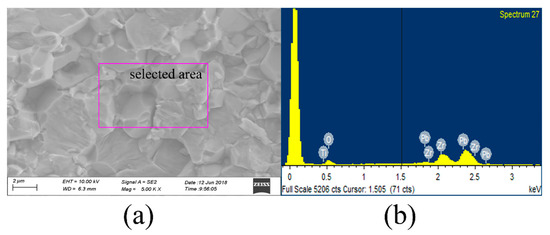
Figure 7.
(a) SEM photo (5000×) of the cross-section of the piezoelectric tube; (b) EDS result of the selected area.

Table 1.
The elemental composition of the piezoelectric tube measured by the EDS test.
3.2. Fabrication Process of the Threaded Motor
The structure of the threaded piezoelectric motor is simple and compact. The prototype consisted of only three parts: a customized PZT tube, two nuts, and a precise screw rod. The detailed fabrication process is represented in the following steps:
- (1)
- clean the electrode surface of the PZT tube with alcohol and dry in air;
- (2)
- connect the ground wire with the inner electrodes;
- (3)
- glue the two nuts with both ends of the PZT tube with epoxy glue to form the stator;
- (4)
- connect the fine wire with the four groups of the outside electrodes;
- (5)
- screw the rod into the stator to finish the fabrication of the prototype.
3.3. Harmonic Response Characteristics
A prototype of the proposed motor was assembled and electrically connected with fine wires as Figure 1b shows. A through-hole (diameter 0.5 mm) in one nut was used to attach the common ground fine wire to the inner electrode.
The harmonic response characteristic of the stator in the prototype was obtained by using a 2D scanning laser Doppler vibrometer (PSV-400-M2, Polytec, Germany) and a 3D scanning laser Doppler vibrometer (MSA-100-3D, Polytec, Germany). The result is demonstrated in Figure 8, and it shows that the required B2 resonant frequency was 31.9 KHz.
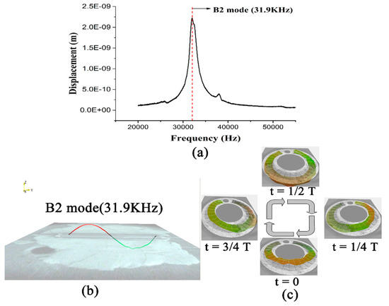
Figure 8.
(a) Maximum vibration displacement over the frequency of the prototype (Vpp= 20 V); (b) The B2 mode shape measured by a 2D laser Doppler vibrometer; (c) The wobbling motion of the stator within a single period measured by a 3D laser Doppler vibrometer (frequency = 31.9 KHz).
Figure 8a shows the vibration displacement curve over the frequency of the proposed motor at a voltage of 20 Vpp (Vpp means the peak-to-peak value of the voltage volts). We can see from the curve that there is nearly no other resonant peak except the B2 peak. Then, we gained the visualized B2 mode shape by carrying out a 2D laser Doppler measurement as shown in Figure 8b. Thus, the eight-zonal pattern of the electrode partition and the corresponding electric exciting mode proved to be effective. Finally, the wobbling motion of the stator within a single period was confirmed in Figure 8c by using a 3D laser Doppler vibrometer, as this laboratory apparatus can measure not only the out-of-plane vibration like the traditional 2D vibrometer but also the in-plane vibration of the prepared sample.
3.4. Mechanical Characteristics
The threaded actuatorwas designed for precise positioning applications with requirement of low driving voltage and high thrust. The performance was evaluated based on measurements including the linear speed (moving velocity), output force with respect to frequency, and driving voltage. The four groups of electric signals with ±90° phase shifts were generated by a dual channel DDS signal generator (Model: MHS-2300A, China) and then amplified by a power amplifier (ML3860B, Yangdianguoxun, China). As shown in Figure 9, the actuator was clamped horizontally at the middle nodal line (as shown in Figure 2) for minimal mechanical interference, and the continuous displacement of the threaded shaft with no load was measured using a laser displacement sensor (optoNCDT 2300, Micro-Epsilon, Germany). Moreover, a digital force gauge (ZP-5N, Imada, Japan) with a resolution of 0.1 N was employed to measure the stall force of the threaded shaft when the velocity was set to zero.
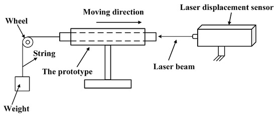
Figure 9.
Mechanical characteristics of the testing system.
The relationship between the no-load linear velocity of the actuator and the driving frequency at 40 Vpp driving voltage is illustrated in Figure 10. The maximum velocity was 4.9 mm/s when the driving frequency was set to 31.2 KHz. When the frequency was lower than 23.7 KHz or higher than 40.1 KHz, the motor could hardly work normally.
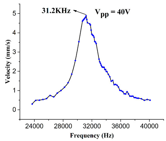
Figure 10.
Linear velocity versus the driving frequency at 40 Vpp.
By comparison with the result of the laser Doppler experiment, these two resonant frequencies measured had a slight difference of 0.7 KHz, which could be ignored. The error might have come from the coupling of nuts and threaded rod when rotating as the motor remained still when it was measured by the laser Doppler vibrometer for only half signals was applied to it.
It can be concluded that the proposed motor can work smoothly at a fairly low driving voltage in a frequency band with a bandwidth of over 5 KHz, which is wide enough for the design of control circuits and practical applications.
Figure 11 shows the relationship between the output performance of the motor and the voltage amplitude at frequency 31.2 KHz. As the effective traveling range of the motor was about 20 mm, the examined voltage amplitude ranged from 0 Vpp to 60 Vpp for fine movement. Both the linear velocity and the stall force increased with elevation of the voltage amplitude, and the maximum stall force at a voltage of 40 Vpp was about 5.0 N. Good linearity can be observed from the curves of linear speed and stall force over the voltage amplitude, showing fine output performance controllability.
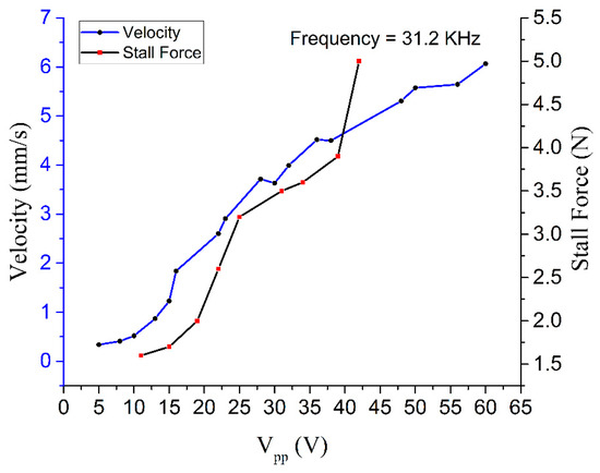
Figure 11.
Linear velocity and stall force vs. driving voltage of the motor.
The velocity vs. pulling force characteristics are shown in Figure 12, and we applied the pulling force by hanging a weight to the screw rod. Five different amplitudes of the sinusoidal voltage—20, 30, 40, 50, and 60 Vpp—were adopted and the frequency was set to 31.2 KHz in this experiment. The result shows firstly that the bigger the applied pulling force is, the smaller is the velocity of this motor; secondly, the velocity is bigger when the applied voltage is higher under the same pulling force condition. Through Figure 12, the mechanical power of the motor can be calculated (the mechanical power equals the product of the velocity and the pulling force). From the curve of mechanical power vs. pulling force it can be concluded that the maximum mechanical power at 40 Vpp was 1.24 mW. The inertia of the rod was ignored in the calculation process of the pulling force. Thus, the mechanical power when there was no pulling force applied to it was zero.
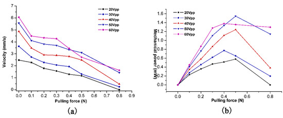
Figure 12.
(a) Velocity vs. pulling force at various voltages; (b) Mechanical power vs. pulling force at various voltages.
4. Conclusions
In this paper, we proposed an eight-zonal piezoelectric tube-type threaded ultrasonic motor based on a second-order bending vibration mode. The actuator consisted of just a PZT tube (inside diameter 5.35 mm, outside diameter 6.35 mm, length 30 mm), two nuts, and a screw rod (diameter 3 mm, length 50 mm), and its weight was about 5.67 g. The working mechanism was discussed, and relative experiments were conducted.
The eight-zonal piezoelectric tube-type threaded ultrasonic motor has some design merits compared to other cylindrical types. Firstly, the ceramic tube stator design avoids glue layers between the PZT pieces and the metal substrate compared to the surface-bonded type [12], which prevents the vibration energy loss in glue layers and extends the life-span of motors. Secondly, compared to the Langevin stator design [14], the ceramic tube stator design is easier for miniaturization and can work normally under a lower voltage. Thirdly, compared to thin-film deposition design [11], the ceramic is thicker for applying a higher voltage and gains better output performance. Finally, the second-bending mode design is more suitable for clamping without any influence on motor performance.
The experiment results show that the threaded motor can output a stall force of about 5.0 N and a linear velocity of 4.9 mm/s with no load at the driving voltage of 40 Vpp. It was verified that the structure design based on the coupling of second-order bending modes is appropriate for linear or rotary cylindrical piezoelectric actuators. The advantages of fine output performance at low driving voltage, fairly suitable bandwidth, compact structure, and simple fabrication of this threaded ultrasonic motor make it competitive in some precise micro-positioning applications. Further research will focus on improving the speed controllability and miniaturizing the whole system.
Author Contributions
All authors conceived and designed the experiments and analyzed the data; M.Z. accomplished the finite element analysis; X.C. and S.Y. contributed to the theoretical analysis and modified this paper. X.Z. and M.Z. performed the experiments; all authors contributed to the writing of the paper.
Acknowledgments
This work was financially supported by the National Natural Science Foundation of China (Grant No. 51775304). The authors are indebted to the financial supports to accomplish this research.
Conflicts of Interest
The authors declare no conflict of interest.
References
- Morita, T. Miniature piezoelectric motors. Sens. Actuators A 2003, 103, 291–300. [Google Scholar] [CrossRef]
- Peng, Y.X.; Peng, Y.L.; Gu, X.Y.; Wang, J.; Yu, H.Y. A review of long range piezoelectric motors using frequency leveraged method. Sens. Actuators A 2015, 235, 240–255. [Google Scholar] [CrossRef]
- Watson, B.; Friend, J.; Yeo, L. Piezoelectric ultrasonic micro/milli-scale actuators. Sens. Actuators A 2009, 152, 219–233. [Google Scholar] [CrossRef]
- Zhao, Y.Q.; Yuan, S.M.; Chu, X.C.; Gao, S.N.; Zhong, Z.J.; Zhu, C. Ultrasonic micro-motor with multilayer piezoelectric ceramic and chamfered driving tips. Rev. Sci. Instrum. 2016, 87, 095108. [Google Scholar] [CrossRef] [PubMed]
- Spanner, K.; Koc, B. Piezoelectric motors, an overview. Actuators 2016, 5, 6. [Google Scholar] [CrossRef]
- Qin, X. Reduced-Voltage, Linear Motor Systems and Methods Thereof. U.S. Patent 8,217,553-B2, 10 July 2012. [Google Scholar]
- Hunstig, M. Piezoelectric inertia motorsa critical review of history, concepts, design, applications, and perspectives. Actuators 2017, 6, 7. [Google Scholar] [CrossRef]
- Henderson, D.A. Ultrasonic Lead Screw Motor. U.S. Patent 6,940,209-B2, 6 September 2005. [Google Scholar]
- Bekiroglu, E. Ultrasonic motors: Their models, drives, controls and applications. J. Electroceramics 2008, 20, 277–286. [Google Scholar] [CrossRef]
- Morita, T.; Kurosawa, M.; Higuchi, T. An ultrasonic micromotor using a bending cylindrical transducer based on pzt thin film. Sens. Actuators A 1995, 50, 75–80. [Google Scholar] [CrossRef]
- Morita, T.; Kurosawa, M.K.; Higuchi, T. A cylindrical shaped micro ultrasonic motor utilizing pzt thin film (1.4 mm in diameter and 5.0 mm long stator transducer). Sens. Actuators A 2000, 83, 225–230. [Google Scholar] [CrossRef]
- Koc, B.; Cagatay, S.; Uchino, K. A piezoelectric motor using two orthogonal bending modes of a hollow cylinder. IEEE Trans. Ultrason. Ferroelectr. Freq. Control 2002, 49, 495–500. [Google Scholar] [CrossRef] [PubMed]
- Kanda, T.; Makino, A.; Ono, T.; Suzumori, K.; Morita, T.; Kurosawa, M.K. A micro ultrasonic motor using a micro-machined cylindrical bulk pzt transducer. Sens. Actuators A 2006, 127, 131–138. [Google Scholar] [CrossRef]
- Chu, X.C.; Wang, J.W.; Yuan, S.M.; Li, L.T.; Cui, H.C. A screw-thread-type ultrasonic actuator based on a langevin piezoelectric vibrator. Rev. Sci. Instrum. 2014, 85, 065002. [Google Scholar] [CrossRef] [PubMed]
- Chang, L.K.; Tsai, M.C. Design of single-phase driven screw-thread-type ultrasonic motor. Rev. Sci. Instrum. 2016, 87, 055002. [Google Scholar] [CrossRef] [PubMed]
- Park, S.; He, S. Standing wave brass-pzt square tubular ultrasonic motor. Ultrasonics 2012, 52, 880–889. [Google Scholar] [CrossRef] [PubMed]
- Dong, S.X.; Lim, S.P.; Lee, K.H.; Zhang, J.D.; Lim, L.C.; Uchino, K. Piezoelectric ultrasonic micromotor with 1.5 mm diameter. IEEE Trans. Ultrason. Ferroelectr. Freq. Control 2003, 50, 361–367. [Google Scholar] [CrossRef] [PubMed]
- Wallaschek, J. Contact mechanics of piezoelectric ultrasonic motors. Smart Mater. Struct. 1998, 7, 369–381. [Google Scholar] [CrossRef]
© 2019 by the authors. Licensee MDPI, Basel, Switzerland. This article is an open access article distributed under the terms and conditions of the Creative Commons Attribution (CC BY) license (http://creativecommons.org/licenses/by/4.0/).