Abstract
The Nuss procedure is one of the most widely used operation techniques for pectus excavatum (PE) patients. It attains the normal shape of the chest wall by lifting the patient’s chest wall with the Nuss bar. However, the Nuss bar is for the most part bent by a hand bender according to the patient’s chest wall, and this procedure causes various problems such as the failure of the operation and a decreased satisfaction of the surgeon and patient about the operation. To solve this problem, we proposed a method for deriving the optimal operation result by designing patient-specific Nuss bars through computer-aided design (CAD) and computer-aided manufacturing (CAM), and by performing auto bending based on the design. In other words, a three-dimensional chest wall model was generated using the computed tomography (CT) image of a pectus excavatum patient, and an operation scenario was selected considering the Nuss bar insertion point and the post-operative chest wall shape. Then, a design drawing of the Nuss bar that could produce the optimal operation result was derived from the operation scenario. Furthermore, after a computerized numerical control (CNC) bending machine for the Nuss bar bending was constructed, the Nuss bar prototype was manufactured based on the derived design drawing of the Nuss bar. The Nuss bar designed and manufactured with the proposed method has been found to improve the Haller index (HI) of the pectus excavatum patient by approximately 37% (3.14 before to 1.98 after operation). Moreover, the machining error in the manufacturing was within ±5% compared to the design drawing. The method proposed and verified in this study is expected to reduce the failure rate of the Nuss procedure and significantly improve the satisfaction of the surgeon and patient about the operation.
1. Introduction
Pectus excavatum is one of the most well-known chest wall deformities, in which the entire chest including the costal cartilage and sternum is depressed due to the overgrowth of the costal cartilage. The exact cause of PE has not been accurately identified, and it affects about one in every 300 children worldwide. For these patients, the PE operation is strongly recommended since the major organs in the chest such as the heart and lungs can be subjected to pressure, and problems such as the degradation of cardiopulmonary function, growth, and physical activities are likely to be caused by PE [1,2]. Furthermore, the PE operation is also required to solve potential problems related to cosmetic and mental aspects, such as the avoidance of interpersonal relationships.
The PE operations include the Ravitch procedure, sternal turnover operation, Silastic molding method, and Nuss procedure. The Ravitch procedure and the sternal turnover operation, which are called open surgery, require a resection of all deformed costal cartilage. They can correct the chest wall effectively, but it has disadvantages such as a large operation range, a long operating time, and a less cosmetic effect. The Silastic molding method is a minimally invasive surgery that is used for cosmetic effect, but this method cannot solve the problems of physical function. [3,4].
On the other hand, the Nuss procedure, one of the minimally invasive surgeries, was introduced in 1998 by Donald Nuss, a thoracic surgeon. In this method, a metal bar called a Nuss bar is inserted through the ribs and placed below the sternum to lift the depressed chest. It is widely popular worldwide owing to a small surgical wound, a low risk of infection, and a better cosmetic advantage [5,6]. Hence, the Nuss procedure was selected in the present study.
There are several types of PE, for example, symmetrical, asymmetrical, eccentric, and unbalanced types. Accordingly, the proper type of the Nuss bar should be fabricated prior to operation in order to correct the PE accurately and effectively [7]. However, most Nuss bars are manufactured in a straight shape and provided as such to surgeons. For this reason, the surgeons must manually bend the Nuss bar based on their intuition. However, it is extremely difficult to make a patient-specific shape of the Nuss bar during operation. In addition, the Nuss bar can be damaged due to the repeated bending process, and the adjacent tissues can be damaged if the Nuss bar has a sharp angle.
In order to overcome the above obstacle, Lin et al. [8] adopted the three-dimensional (3D) printing method to fabricate a patient-specific Nuss bar. In their research, the polylactic acid-based 3D printed Nuss bar was developed and implemented into 10 PE patients. They called this novel operation the 3DPMAN (3D Printed Model-Assisted Nuss) procedure, and the initial results of the 3DPMAN procedure was feasible, easy, convenient, and satisfactory.
There are many advantages in fabricating the Nuss bar using polymer 3D printing such as the low fabrication cost, the short fabrication time, and others. However, the polymer Nuss bar has severe shortcomings. The Nuss bars are usually made of titanium alloys or stainless steel since they can maintain high stiffness and strength until they are removed from the body. Accordingly, the chest wall, including the Nuss bar, may be free from sudden failure or fracture due to unexpected excessive external forces. On the other hand, the polymer Nuss bars, such as polylactic acids, have low strength and stiffness compared to titanium alloys or stainless steel. Therefore, the mechanical evaluation of material/structural safety should be sufficiently carried out prior to clinical applications.
If the Nuss bar is made using metal 3D printing, the procedure is costly and time-consuming. In other words, the metal powder (titanium alloy powder) is quite expensive, and the 3D printing takes a great amount of time. In addition, the metal 3D printed Nuss bar must be properly surface treated, and thus requires much time and cost. If the surface is poorly treated, the metal powder can be absorbed into the human body and is extremely dangerous.
Due to the various problems described above, we adopted a method for bending a titanium alloy Nuss bar to the expected normal chest wall shape after the patient’s operation. For this, we proposed a method for deriving the optimal operation result of PE patients based on (1) technology to design the patient-specific Nuss bar using a three-dimensional (3D) chest wall model (CAD method) and (2) technology to fabricate the patient-specific Nuss bar using an auto bending machine (CAM method).
2. Materials and Methods
2.1. Fabrication Procedure for the Patient-Specific Nuss Bar via CAD and CAM
The fabrication procedure for the patient-specific Nuss bar can be divided into a design process for the patient-specific Nuss bar (CAD) and a machining process for fabricating the designed Nuss bar (CAM). The overall flow for the fabrication procedure is shown in Figure 1. The detailed procedures are described sequentially in the following chapters.
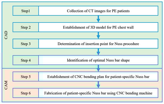
Figure 1.
Fabrication procedure for the patient-specific Nuss bar.
2.2. Modeling of the Three-Dimensional (3D) Chest Wall for a Pectus Excavatum Patient
2.2.1. Collection of CT Images for PE Patients
The first step for deriving the 3D chest wall of a PE patient is to collect the medical imaging data of the PE patients. We collected computed tomography (CT) images of 15 PE patients from the Pusan National University Hospital, and classified them based on the chest wall shape into symmetrical and asymmetrical types. Ten patients with a symmetrical depression based on the center of the sternum were included in the symmetric group, and five patients with a depression deviated from the center of the sternum or an asymmetrical depression were included in the asymmetric group.
In general, CT, magnetic resonance imaging (MRI), ultrasound, and other methods can be adopted to fabricate the 3D surface and finite element (FE) model for several organs of the human body. For example, Bonacina et al. [9] have developed a novel algorithm that automatically extracts the facial surface from ultrasound images. Using this method, they fabricated a 3D foetal face model without any human intervention or training procedure.
However, in this study, the CT image was adopted from among various medical images. The reason is that in the case of MRI, the image can be distorted due to the patient’s breathing, and in the case of ultrasound, it is not easy to generate a 3D surface and FE model using general-purpose medical image processing software such as Materialise MIMICS due to the noise.
2.2.2. Establishment of 3D Model for PE Chest Wall
For our study, 3D chest wall models were fabricated based on the obtained patient CT images. The models were then used to design patient-specific Nuss bars. The image processing software MIMICS version 17 from Materialise (Leuven, Belgium) was used to produce the 3D chest wall model. From the original CT images, 12 ribs, sternums, and costal cartilages were extracted in the following four steps (see Figure 2).
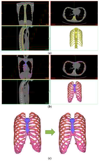
Figure 2.
Fabrication procedure for the 3D chest wall model for a PE patient: (a) Step 1; (b) Steps 2 and 3; (c) Step 4.
- Step 1: The CT file of a patient is loaded into the program (MIMICS). The loaded CT image is displayed in black and white depending on the density of each tissue. Thus, the density differences between tissues are used to select the desired body organ on the screen. The density range is specified using the “Thresholding” feature. The 3D surface can be obtained by selecting the rib and sternum tissues easily using the default value (bone region) of each tissue provided by the “Region growing” function of the program.
- Step 2: A 3D model is created from the obtained 3D surface using the “3D calculation” feature. The spine or any other unnecessary tissues are removed using “Edit mask” or similar features because the Nuss bar is not applied to them.
- Step 3: A separate selection task must be performed to obtain the 3D surface of costal cartilage because the costal cartilage region cannot be taken with the Bone default value due to its low density compared to the rib and sternum. A 3D model is created from the 3D surface of the costal cartilage obtained through this separate process.
- Step 4: A smooth-shaped chest wall model is produced finally by modifying the 3D chest wall models of the rib, sternum, and costal cartilage using the “Wrap” and “Smoothing” features.
2.3. Virtual Surgery Scenario for Nuss Procedure
2.3.1. Definition of Haller Index
Two conditions must be considered when performing the Nuss procedure. The first condition is that the Haller index (HI) must be an HI value of a normal chest wall. The second condition is that the damage of the Nuss bar and its adjacent tissues must be minimized. In order to satisfy these two conditions, the insertion point and shape of the Nuss bar must be determined before performing the Nuss procedure. In this study, the optimal operation position and shape were found by quantitatively deriving the Haller index values before and after operation for each Nuss bar insertion point based on the actual CT images of the patients.
Figure 3 shows the pectus indices. The Haller index is a simple mathematical method for measuring and representing PE with a known pectus index. It is calculated by the ratio of the maximum transverse diameter (the maximum length inside the thoracic cage, A) measured on the axial CT section of the chest with the largest deformation and the minimum anterior-posterior (AP) distance (minimum distance between the spine and the sternum, B) [10,11,12].
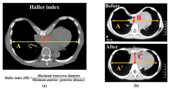
Figure 3.
Illustration of pectus indices calculated from the computed tomography (CT) axial image with greatest sternum depression: (a) description of the Haller index; (b) measurement of the Haller index before and after the Nuss operation.
Equation (1) is the Haller index equation before the Nuss operation:
Pre-operation: HI = A/B.
The Haller index expected after the PE operation is called the ideal chest index (ICI), which is determined by dividing the corrected maximum transverse diameter (A’) by the corrected minimum AP distance (C) [13].
Equation (2) is the ideal chest index (ICI) equation, which is used instead of the Haller index after the Nuss operation:
Post-operation: ICI = A′/C.
The severity degree of PE is classified by the HI value. Dr. Mark Thurston classified the degree of PE by HI value as is shown in Table 1 [14].

Table 1.
Classification of the Haller index.
According to the results of many studies that investigated the correlations between HI and PE, the PE operation is required if the HI is equal to or greater than 3.2 [11,15].
2.3.2. Virtual Surgery Scenario for Insertion Point and Shape Design of Nuss Bar
The virtual surgery scenario for selecting the optimal insertion point and shape was set as follows [16]. Three points were selected based on the ribs around the sternum with the largest depression using the CT image and 3D model of Patient 1. As is shown in Figure 4, insertion point A is the sternum between the second and third ribs, insertion point B is between the third and fourth ribs, and insertion point C is between the fourth and fifth ribs.
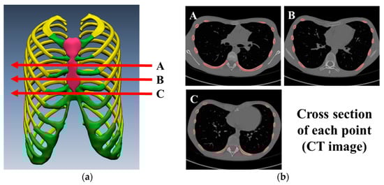
Figure 4.
Virtual surgery scenario for insertion point and shape design of Nuss bar: (a) Nuss bar is inserted at A, B, and C points from 3D chest wall model; (b) CT axial images with insertion points A, B, and C.
Figure 5 shows the chest wall shape expected after the Nuss procedure for each insertion point. The blue line on the CT image is the optimal Nuss bar shape, which was designed by referring to the PE shape type and the shape of a similar chest wall.
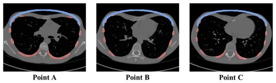
Figure 5.
Illustrations of corrected sternum after Nuss bar insertion. The same shape of the Nuss bar was located on the CT axial image with insertion points.
To fabricate a patient-specific Nuss bar based on the patient’s CT image, a computerized numerical control (CNC) bending machine that can machine every curved surface within the range of the Nuss bar curves must be first constructed. In this study, a CNC bending machine was constructed with the machining purpose.
2.4. Establishment of Computerized Numerical Control (CNC) Bending Machine for Patient-Specific Nuss Bar
2.4.1. Components and Modification of CNC Bending Machine
Figure 6 shows the components of the equipped CNC bending machine which consists of a main body, control cabinet, and air pump. Of these, the main body where the material shaping occurs is largely divided into feeding and rotation units and a bending unit.
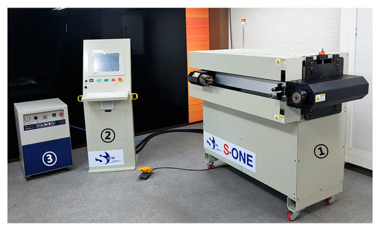
Figure 6.
Establishment of CNC bending machine. In the figure, components of the CNC bending machine are (1) main body, (2) control cabinet, and (3) air pump.
Figure 7 shows the feeding and rotation units in the main body. The feeding and rotation unit assembly (Figure 7a) consists of a feeder module which pushes the material to the bending head, a set of clamps which holds the material, and a rotation module that rotates the material. The existing set of clamps is designed for round materials such as wire and rod, and cannot hold the Nuss bar material with the bar shape. Therefore, a customized jig for the Nuss bar was designed, fabricated, and mounted onto the clamps (Figure 7b).
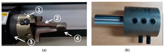
Figure 7.
Images of feeding and rotation parts of the CNC bending machine: (a) image of the feeding and rotation assembly, composed of the (1) rotation module, (2) set of clamps, (3) feeding module, and (4) Nuss bar jig; (b) image of the customized jig tool for Nuss bar processing.
The design drawing of the jig for the Nuss bar is shown in Figure 8, which was designed considering the specifications of the machined material (width of metal bar: 13 mm, thickness of metal bar: 3 mm).
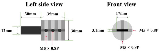
Figure 8.
Left and front view of Nuss bar jig design. Designed jig is holding metal bar during the production process of patient-specific Nuss bar by CNC bending machine.
Figure 9 shows the bending unit for bending of the material. The bending unit is composed of multiple tools and is designed to be able to machine 180° rotations at the maximum with 90° in two directions (clockwise and counterclockwise) considering the characteristics of the material (for metal bar, rotation by the rotation unit is impossible). The Nuss bar machining limits of existing tools were overcome by manufacturing a tool that could perform bidirectional bending.
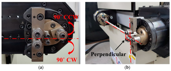
Figure 9.
Bending unit for Nuss bar manufacturing by CNC bending machine. (a) This picture shows the maximum range of movement of the bending tool. (b) This picture shows the Nuss bar (straight) being inserted into the machine; the Nuss bar makes a 90-degree angle with the bending unit.
The control cabinet, which is another component of the CNC bending machine, is used to input the machining data and manage the device-operating options, and the CAM software, which is the machining program, is embedded in it. In addition, a separate air pump must be installed for material feeding.
2.4.2. Installation and Specification of CNC Bending Machine
The metal body frame of the CNC bending machine must be installed on a concrete floor and maintain horizontal balance. The control cabinet must be fixed by wheel brake pedals and all cables connected to the main body must be protected. The specifications of the machine including power consumption, electrical requirement, and air requirement are shown in Table 2.
Table 2.
Specification of the CNC bending machine.
2.4.3. Operation Parameters of CNC Bending Machine
The parameters for machine operation such as home position and initial position can be set using the parameters function of the CAM program. Table 3 shows the parameter list and values of the CNC bending machine set for the fabrication of the patient-specific Nuss bar.
Table 3.
Operating parameter values to operate the CNC bending machine for the Nuss bar.
The accurate bending of materials requires the setting of the tool geometry. After selecting the material and tool in the material selection choice, the Bender Geometry window (click on tool definitions icon) is activated and the appropriate tool geometry is set for the Nuss bar machining.
In this study, the mandrel type tool was selected as the default tool. Table 4 shows the main setting values of the tool geometry for accurate machining of a linear Nuss bar.
Table 4.
Tool geometry setting values for increasing accuracy of bending result.
3. Results
3.1. Validation of CAD-Based Patient-Specific Nuss Bar Design Technology
To fabricate the patient-specific Nuss bar, we reviewed the CT images of 15 patients and chose one symmetric case called Patient No. 1 from the symmetric group. Then, we proposed three surgery scenarios (Nuss bar insertion points) to derive the patient-specific Nuss bar shape and select the insertion point for Patient No. 1.
The HI value before and after inserting the Nuss bar was calculated for each scenario. The pre- and post-operative maximum transverse diameters (A, A’) and the minimum AP distances (B, C), and HI values are summarized in Table 5.
Table 5.
Haller index values before and after the Nuss procedure in Patient No. 1.
According to a previous study, the post-operative maximum transverse diameter is 95% of the pre-operative value [17]. The post-operative maximum transverse diameter (A’) was derived by applying the results of the corresponding study.
Figure 10 shows the pre- and post-operative minimum AP distances according to the Nuss bar insertion point.
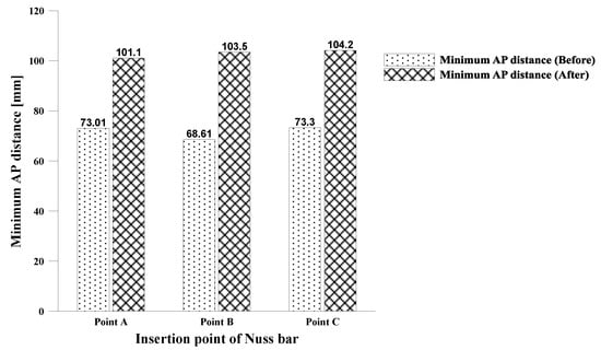
Figure 10.
Minimum AP distance before and after the Nuss procedure. Values of minimum AP distance with Nuss bar insertion points are shown by histogram.
The B (Pre-operative) values for each insertion point (points A, B, and C) were measured at 73.01 mm, 68.61 mm, and 73.30 mm, respectively. The smallest value was obtained at position B. The C values for each insertion point were 101.11 mm, 103.49 mm, and 104.15 mm, respectively. The largest value was obtained at position C. The minimum AP distance increased by 38.49%, 50.84%, and 42.09% at the insertion points, respectively. Thus, position B showed the largest increase.
Figure 11 shows the changes in HI values before and after the Nuss procedure.
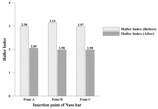
Figure 11.
Haller index before and after the Nuss procedure. The values of the Haller index with insertion points of the Nuss bar are shown in the histogram.
The post-operative HI value decreased by 31.31% from 2.98 to 2.01 at insertion point A, by 36.94% from 3.14 to 1.98 at insertion point B, and by 33.33% from 2.97 to 1.98 at insertion point C. At every insertion point, the HI value improved by more than 30%. Furthermore, the improved HI values were near the target HI value of a normal chest wall (HI < 2.5).
The data analysis results revealed that the minimum AP distance and HI improved the most at point B that had the largest HI value before operation. Therefore, the optimal insertion point was confirmed to be B which had a corrected HI value lower than 2.0 and showed the greatest change.
Using the Nuss bar design technology which is described in Section 2.3, we derived the Nuss bar design for asymmetric PE patients (Figure 12). Patients Nos. 2 and3 represent the eccentric and unbalanced PE patients, respectively.
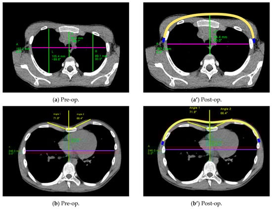
Figure 12.
CT images of asymmetric patients. (a) and (b) are CT images taken before the Nuss operation; (a’) and (b’) are images taken after the Nuss operation. Yellow lines in (a’) and (b’) show the patient-specific Nuss bar.
The insertion position and shape of the patient-specific Nuss bar are derived using corrected HI values. Additionally, the angle and height on the left and right side of chest have similar values after the Nuss procedure, which is for the cosmetic aspect. Table 6 shows the corrected HI values after Nuss bar insertion.
Table 6.
Haller index before and after the Nuss procedure in Patients Nos. 2 and 3.
After Nuss bar insertion, the HI values of the eccentric case decreased by 31.9% from 3.26 to 2.22 in the insertion position A. In the unbalanced case, the HI values after Nuss bar insertion decreased by 30% from 3.39 to 2.37 in the insertion position C. The corrected HI value of both patients (eccentric and unbalanced) are below 2.5 (normal range of HI).
3.2. Validation of CAM-Based Patient-Specific Nuss Bar Fabrication Technology
3.2.1. Bending Test for Patient-Specific Nuss Bar Fabrication
Before fabricating the patient-specific Nuss bar, a bending test was performed to verify the bending range and machining accuracy of the equipped CNC bending machine.
• Drawing of Test Design: Central Arc and Transition Value of Nuss Bar
A product drawing for machining test considering the maximum/minimum values of the arc and transition parts of the Nuss bar components was created. Figure 13 shows the components of the Nuss bar [18].
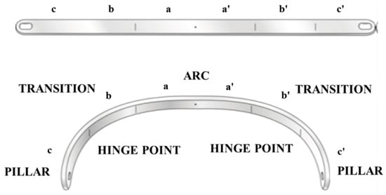
Figure 13.
Three components of the Nuss bar. Arc and transition were used to draw the test sample for the bending test.
(1) Central arc design: This part lifts the depressed sternum and is divided into five steps by selecting 200–400 mm for the maximum/minimum lengths of the transverse diameter (50 mm intervals). The maximum/minimum AP distances are determined by using the HI [19]. Five drawings were created by using the circumference within 160° from the center of the ellipse shape. (2) Transition part design: The machining occurs predominantly in this part and the applied value varies by the degree of the chest wall deformation [18]. The maximum/minimum radius range of curvature of the transition part was set to 20–100 mm, and was divided into five steps (20 mm intervals). Five drawings were created with the representative angles of 30°, 60°, and 90° for each curvature.
• Computer-Aided Manufacturing (CAM) Data and Fabrication of Test Designs
The test products were fabricated using the biocompatible metal Titanium-6Al-4V ELI (Ti-Gr5) and SUS 316 LVM (SUS) with a thickness of 3 mm and a width of 13 m. The bending method varied according to the product shape. The feeding method was applied when the curvature of an ellipse shape was low and machining over a wide range was required such as for the central arch. The multi-bending method was applied if different bending methods had to be performed for each narrow point such as for the transition type.
The desired machining result could not be obtained from the initial CNC bending test where the design specifications were applied. In particular, Ti-Gr5 generated greater machining errors due to a strong springback phenomenon compared to SUS.
The springback, which is a property that makes the material return to its original shape, is affected by the material properties (yield strength, modulus of elasticity) and thickness, machining angle, and bending radius [20,21,22].
Therefore, the CAM data were established considering the springback phenomenon of materials to perform accurate bending. First, the initial springback factor, Ks, of each material was calculated as is shown in Figure 14. To calculate the initial Ks value, the data for each factor in Table 7 were input into the Bending Springback Calculator (Figure 14) of CUSTOMPART.NET.
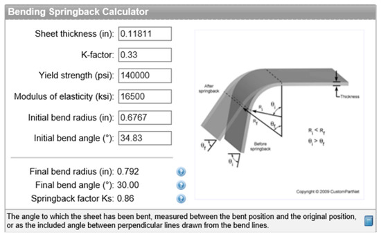
Figure 14.
Bending Springback Calculator from CUSTOMPART.NET [23]; springback factor (Ks), final bend radius (FR), and final bend angle are changed by input values which are sheet thickness (Mt), K-factor, yield strength, elasticity, initial bend angle, and initial bend radius (IR).
Table 7.
Data of springback factors.
The CAM data (machining angle and radius value) for the final angle and radius values were calculated reversely by applying the initial Ks value to the springback factor (Ks) equation, Equation (3) [24], as follows:
where IR and FR are the initial and final bend radii, respectively, and Mt is the sheet thickness.
The CAM data according to the material, angle, and bending radius were determined through multiple bending trials and errors. Different CAM values were required depending on the material even if a Nuss bar of the same shape was fabricated. The Ti-Gr5 product required additional bending between 2% to 20% as compared to the SUS product.
The prototypes of the central arc and transition values were fabricated using the appropriate machining method and the derived CAM values.
• Results of Bending Test
The machining accuracies of 60 prototypes in total were evaluated through measurement of dimensions. For the dimension measurement test, the maximum width and height were specified as the major measurement indices. Figure 15 shows the dimension measuring points for machining accuracy.
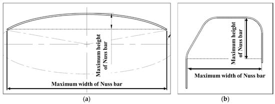
Figure 15.
Designs of test sample: (a) central arc design with measuring point of maximum width and height; (b) transition Nuss bar design with measuring points.
The dimension accuracy results of the five design prototypes considering the central arc were plotted as a graph. Figure 16 shows a graph for the measured width values of central arc designs 1–5 which were fabricated with SUS and Ti-Gr5. The SUS and Ti-Gr5 products have the dimension (width) errors of ±0.41% and ±0.53%, respectively.
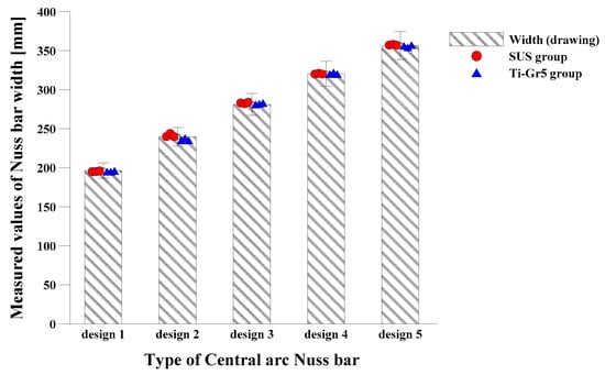
Figure 16.
This histogram shows the dimensions of the Nuss bar. The maximum width of SUS and Ti-Gr5 central arc Nuss bars was measured and compared with original width.
Figure 17 shows the height measurements of the central arc design products. SUS and Ti-Gr5 products have the dimension (height) errors of ±2.61% and ±1.48%, respectively. The major dimension measuring results of Ti-Gr5 and SUS products considering the central arc confirmed that the dimension accuracies of all the prototypes were within ±5%.
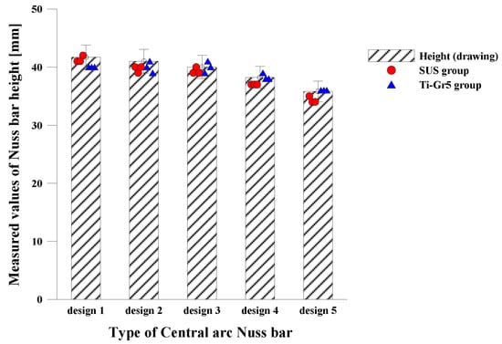
Figure 17.
Results for the dimension accuracy of the central arc Nuss bar. This histogram shows the maximum height of the central arc Nuss bars (SUS and Ti-Gr5). Heights were measured and compared with original height.
The dimension accuracy values of the five designs considering the transition values were plotted as a graph. Figure 18 shows the width of the transition Nuss bars 1–5 fabricated with SUS and Ti-Gr5. The width error is ±1.19% for the SUS product and ±0.57% for the Ti-Gr5 product.
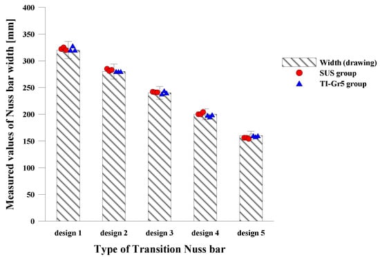
Figure 18.
Results for the dimension accuracy of the SUS and Ti-Gr5 transition Nuss bar. This histogram shows the maximum width of the SUS and Ti-Gr5 transition Nuss bars. Widths were measured and compared with original width.
Figure 19 shows the measured height, and the height errors of the SUS and Ti-Gr5 products are ±1.73% and ±0.9%, respectively. This result confirms that the dimension accuracies of Ti-Gr5 and SUS products considering the transition value are within ±5%.
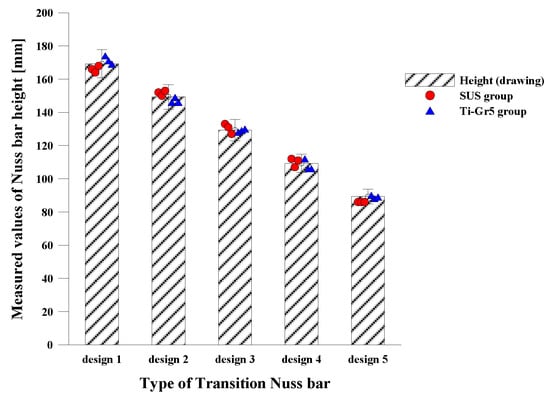
Figure 19.
Results for the dimension accuracy of the SUS and Ti-Gr5 transition Nuss bar. This histogram shows the maximum height of the SUS and Ti-Gr5 transition Nuss bars. Heights were measured and compared with original height.
All values within the central arc and transition values of the Nuss bar can be machined using the auto CNC bending machine, and the bending error range of the bending machine was found to be within ±5%. In particular, it is expected that more accurate machining will be possible for products fabricated with the Ti-Gr5 material.
3.2.2. Manufacture of Patient-Specific Nuss Bar
The patient-specific Nuss bars were fabricated with SUS and Ti-Gr5. The design of the patient-specific Nuss bar was derived using CAD-based design technology, and the product design drawings were created for symmetrical, eccentric, and unbalanced Nuss bar shapes in accordance with the morphological classification of PE [2,7,18,25]. Each type of Nuss bar was designed by collecting CT data and using virtual surgery scenarios, and they represent a different patient group (symmetric, eccentric, and unbalanced group).
Figure 20a–c shows the product design drawings of the three types.
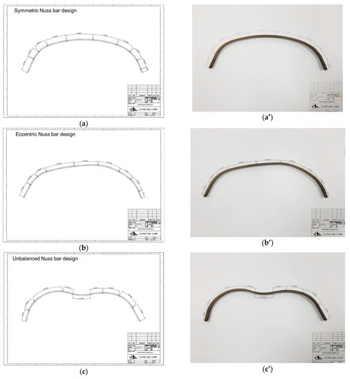
Figure 20.
Three types of patient-specific Nuss bar drawings and products with Ti-Gr5: (a) symmetric Nuss bar design and (a’) symmetric Nuss bar product for Patient No. 1; (b) eccentric Nuss bar design, which was fitted for an asymmetric chest wall patient (Patient No. 2), and (b’) eccentric Nuss bar product; (c) unbalanced Nuss bar design, which was fitted for an asymmetric chest wall patient (Patient No. 3), And (c’) unbalanced Nuss bar product.
A total of 18 patient-specific Nuss bar prototypes were created with three prototypes for each design using the CAM data obtained using the same method. Figure 20a’–c’ shows the fabrication outputs of the patient-specific Nuss bars. Major dimensions were measured to verify the accuracy of the fabricated patient-specific Nuss bar prototypes, and the measurement data and distribution are shown in Table 8 and Figure 21.
Table 8.
Data table for patient-specific Nuss bar dimension accuracy.
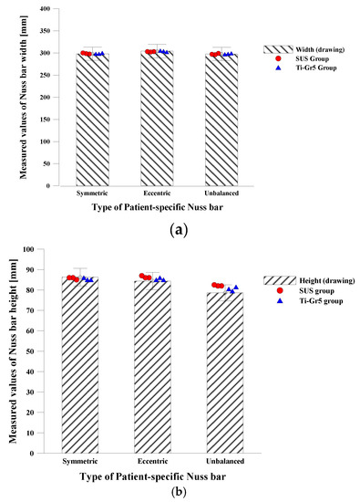
Figure 21.
Dimension accuracy histogram of patient-specific Nuss bar: (a) maximum width of patient-specific Nuss bars was measured after Nuss bar processing and compared with original value; (b) maximum height of patient-specific Nuss bars was measured and compared with original data.
The average dimension accuracies of the titanium and SUS prototypes were ±0.85 % and ±1.47%, respectively. These results show that the patient-specific Nuss bar fabricated with Ti-Gr5 has a higher machining accuracy.
4. Discussion
Since the Nuss procedure was announced by Dr. Nuss in 1997, many Nuss procedures have been carried out and various related studies have been conducted. However, the Nuss bars have been formed by naked eye and experience in the operation room. This study verified the effectiveness of the CAD-based patient-specific Nuss bar design technology for the optimal Nuss procedure.
The CAD-based patient-specific Nuss bar design technology was verified by measuring the Haller index before and after the Nuss procedure. In particular, an increase of the minimum AP distance after the procedure shows that the depressed sternum that pressured the organs inside the chest has been successfully corrected by the patient-specific Nuss bar designed with CAD technology and sufficient internal space has been attained. This method is expected to improve the accuracy and reliability of surgery because the optimal insertion point and correction result of the Nuss bar can be predicted before the actual Nuss procedure.
Furthermore, this study demonstrates the possibility and utility of fabricating the patient-specific Nuss bar through a CNC bending machine using the CAM-based manufacturing technology, and it shows that patient-specific Nuss bars with a dimension error range within ±5% can be fabricated. Using the CAM data for correcting the springback phenomenon for each material and shape will improve productivity because the same products with a certain performance can be manufactured accurately within a short time. However, new CAM data must be constructed if the product shape is changed, or if the material thickness, bending degree, and components are changed even if the product has the same shape. This characteristic will act as a disadvantage when manufacturing diverse products.
5. Conclusions
The CAD/CAM-based patient-specific Nuss bar design and fabrication technology verified in this study will provide a good solution to solve the problems and inconveniences of the current Nuss procedure.
However, the commercialization of the patient-specific Nuss bars fabricated with CAD/CAM-based design and manufacturing technology is still problematic because the CAD-based patient-specific Nuss bar design using the Haller index has limitations with respect to reliability verification and the CAM-based manufacturing method has limitations related to the precise machining of various shapes without establishing the CAM data.
Nevertheless, the proposed method has a positive value in that it can dramatically solve the problem of Nuss bar formation during surgery. In the future, we should obtain clinical data to build the reliability of patient-specific Nuss bars, carry out research based on computer-aided engineering (CAE) to predict the prognosis of the Nuss procedure (e.g., the fixing point of the Nuss bar and the load distribution according to shape)(, and build the CAM database to expand the manufacturing scope of the Nuss bars. Then, we could not only enter the market through the patient-specific Nuss bars, but also secure the possibility of manufacturing various patient-specific orthopedic implants for knees, joints, and spines.
Author Contributions
B.-Y.L. made the 3D model. H.I. developed the general idea of the study, C.-S.L. reviewed and edited paper and supervised the project, J.-Y.H. conceived and designed the study, K.-H.H. performed experiments and collected data, Y.-J.K. wrote the paper and analyzed the data. All authors have read and revised the manuscript.
Funding
This research was supported by a grant from the University Research Park Project of Busan National University funded by the Busan Institute of S & T Evaluation and Planning.
Conflicts of Interest
The authors declare no conflict of interest. The funders had no role in the study design, data collection and analyses, writing of the manuscript, or in the decision to publish the results.
References
- Kilda, A.; Basevicius, A.; Barauskas, V.; Lukosevicius, S.; Ragaisis, D. Radiological assessment of children with pectus excavatum. Indian J. Pediatr. 2007, 74, 143–147. [Google Scholar] [CrossRef] [PubMed]
- Park, H. Minimally Invasive Surgery for Pectus Excavatum&58; Park Technique. J. Clin. Anal. Med. 2011, 2, 84–90. [Google Scholar]
- Lee, J.H.; Kim, S.J.; Kang, J.H.; Chung, W.S.; Kim, H.; Chon, S.H. Silastic molding method for pectus excavatum correction using a polyvinyl alcohol (Ivalon) sponge. Korean J. Thorac. Cardiovasc. Surg. 2012, 45, 418–420. [Google Scholar] [CrossRef] [PubMed]
- Uemura, S.; Nakagawa, Y.; Yoshida, A.; Choda, Y. Experience in 100 cases with the Nuss procedure using a technique for stabilization of the pectus bar. Pediatr. Surg. Int. 2003, 19, 186–189. [Google Scholar] [PubMed]
- Yoon, Y.S.; Kim, H.K.; Choi, Y.S.; Kim, K.; Shim, Y.M.; Kim, J. A modified Nuss procedure for late adolescent and adult pectus excavatum. World J. Surg. 2010, 34, 1475–1480. [Google Scholar] [CrossRef] [PubMed]
- Nagasao, T.; Miyamoto, J.; Tamaki, T.; Ichihara, K.; Jiang, H.; Taguchi, T.; Yozu, R.; Nakajima, T. Stress distribution on the thorax after the Nuss procedure for pectus excavatum results in different patterns between adult and child patients. J. Thorac. Cardiovasc. Surg. 2007, 134, 1502–1507. [Google Scholar] [CrossRef] [PubMed]
- Park, H.J.; Song, C.M.; Her, K.; Jeon, C.W.; Chang, W.; Park, H.-G.; Lee, S.Y.; Lee, C.S.; Youm, W.; Lee, K.R. Minimally Invasive Repair of Pectus Excavatum Based on the Nuss Principle:An Evolution of Techniques and Early Results on 322 Patients. Korean J. Thorac. Cardiovasc. Surg. 2003, 36, 164–174. [Google Scholar]
- Lin, K.-H.; Huang, Y.-J.; Hsu, H.-H.; Lee, S.-C.; Huang, H.-K.; Chen, Y.-Y.; Chang, H.; Chen, J.-E.; Huang, T.-W. The Role of Three-Dimensional Printing in the Nuss Procedure: Three-Dimensional Printed Model-Assisted Nuss Procedure. Ann. Thorac. Surg. 2018, 105, 413–417. [Google Scholar] [CrossRef] [PubMed]
- Bonacina, L.; Froio, A.; Conti, D.; Marcolin, F.; Vezzetti, E. Automatic 3D foetal face model extraction from ultrasonography through histogram processing. J. Med. Ultrasound 2016, 24, 142–149. [Google Scholar] [CrossRef]
- Archer, J.E.; Gardner, A.; Berryman, F.; Pynsent, P. The measurement of the normal thorax using the Haller index methodology at multiple vertebral levels. J. Anat. 2016, 229, 577–581. [Google Scholar] [CrossRef] [PubMed]
- Robbins, L.P. Pectus excavatum. Radiol. Case Rep. 2011, 6, 460. [Google Scholar] [CrossRef] [PubMed]
- Khanna, G.; Jaju, A.; Don, S.; Keys, T.; Hildebolt, C.F. Comparison of Haller index values calculated with chest radiographs versus CT for pectus excavatum evaluation. Pediatr. Radiol. 2010, 40, 1763–1767. [Google Scholar] [CrossRef] [PubMed]
- Poston, P.M.; Patel, S.S.; Rajput, M.; Rossi, N.O.; Ghanamah, M.S.; Davis, J.E.; Turek, J.W. The correction index: setting the standard for recommending operative repair of pectus excavatum. Ann. Thorac. Surg. 2014, 97, 1176–1180. [Google Scholar] [CrossRef] [PubMed]
- Radiopaedia: Haller Index. Available online: https://radiopaedia.org/articles/haller-index (accessed on 5 March 2018).
- Daunt, S.W.; Cohen, J.H.; Miller, S.F. Age-related normal ranges for the Haller index in children. Pediatr. Radiol. 2004, 34, 326–330. [Google Scholar] [CrossRef] [PubMed]
- Ewert, F.; Syed, J.; Wagner, S.; Besendoerfer, M.; Carbon, R.T.; Schulz-Drost, S. Does an external chest wall measurement correlate with a CT-based measurement in patients with chest wall deformities? J. Pediatr. Surg. 2017, 52, 1583–1590. [Google Scholar] [CrossRef] [PubMed]
- Rha, E.Y.; Kim, J.H.; Yoo, G.; Ahn, S.; Lee, J.; Jeong, J.Y. Changes in thoracic cavity dimensions of pectus excavatum patients following Nuss procedure. J. Thorac. Dis. 2018, 10, 4255–4261. [Google Scholar] [CrossRef] [PubMed]
- Wall, C.; Group, I.; Chest, O.N.; Diseases, W. Effect of radiotherapy after mastectomy and axillary surgery on 10-year recurrence and 20-year breast cancer mortality: meta-analysis of individual patient data for 8135 women in 22 randomised trials. Lancet 2014, 383, 2127–2135. [Google Scholar]
- Rebeis, E.B.; de Campos, J.R.M.; Fernandez, Â.; Moreira, L.F.P.; Jatene, F.B. Anthropometric index for pectus excavatum. Clinics 2007, 62, 599–606. [Google Scholar] [CrossRef] [PubMed]
- Damián-Noriega, Z.; Pérez-Moreno, R.; Villanueva-Pruneda, S.A.; Domínguez-Hernández, V.M.; Puerta-Huerta, J.P.A.; Huerta-Muñoz, C. A new equation to determine the springback in the bending process of metallic sheet. In Proceedings of the ICCES: International Conference on Computational & Experimental Engineering and Sciences, Crete, Greece, 25–30 September 2008; Volume 8, pp. 25–30. [Google Scholar]
- Narita, K.; Niinomi, M.; Nakai, M.; Akahori, T.; Tsutsumi, H.; Oribe, K. Bending fatigue and spring back properties of implant rods made of β-type titanium alloy for spinal fixture. In Advanced Materials Research; Trans Tech Publications: Stafa-Zurich, Switzerland, 2010; Volume 89, pp. 400–404. [Google Scholar]
- Adamus, J.; Lacki, P.; Motyka, M.; Nitkiewicz, Z. Analysis of titanium sheet bending process. Inż. Mater. 2010, 31, 716–719. [Google Scholar]
- CUSTOMPART.NET: Spring Back Calculator. Available online: https://www.custompartnet.com/calculator/bending-springback (accessed on 12 April 2018).
- SM: Spring Back. Available online: http://sheetmetal.me/tooling-terminology/spring-back/ (accessed on 2 April 2018).
- Brown, A.L.; Cook, O. Cardio-respiratory studies in pre and post operative funnel chest (Pectus excavatum). Dis. Chest 1951, 20, 378–391. [Google Scholar] [CrossRef] [PubMed]
© 2018 by the authors. Licensee MDPI, Basel, Switzerland. This article is an open access article distributed under the terms and conditions of the Creative Commons Attribution (CC BY) license (http://creativecommons.org/licenses/by/4.0/).