Abstract
In this paper, we show that light-diffusing fibers (LDF) can be efficiently used as host material for surface plasmon resonance (SPR)-based refractive index sensing. This novel platform does not require a chemical procedure to remove the cladding or enhance the evanescent field, which is expected to give better reproducibility of the sensing interface. The SPR sensor has been realized by first removing the cladding with a simple mechanical stripper, and then covering the unclad fiber surface with a thin gold film. The tests have been carried out using water–glycerin mixtures with refractive indices ranging from 1.332 to 1.394. The experimental results reveal a high sensitivity of the SPR wavelength to the outer medium’s refractive index, with values ranging from ~1500 to ~4000 nm/RIU in the analyzed range. The results suggest that the proposed optical fiber sensor platform could be used in biochemical applications.
1. Introduction
Refractive index (RI) sensing is important for biological and chemical applications since a number of substances can be detected through measurements of the refractive index. Among RI sensors, those based on surface plasmon resonance (SPR) are especially useful as they permit label-free and real-time detection of biological/biochemical binding reactions [1,2,3]. In particular, fiber-optic SPR probes have the advantages of remote sensing, continuous analysis, and in situ monitoring. Fiber-optic SPR sensors meet the demands of time- and space-saving, low sample volume, low cost, high sensitivity, portability, and miniaturization. Therefore, these biosensors have recently been extensively investigated [4,5,6]. Numerous versions have been introduced, exploiting several kinds of optical fibers and/or different manufacture procedures, in an attempt to optimize the sensitivity of the plasmonic sensor platforms [7,8,9,10,11,12,13,14].
In general, the excitation of a surface plasma wave at the boundary between a thin metal film and the surrounding medium requires access to the evanescent part of propagating light [13]. In single-mode fibers, this requires a chemical etching of the cladding, which increases the cost of manufacturing and impacts on the robustness of the sensor. In multimode fibers with polymeric cladding (the so-called hard-clad fibers), the cladding may be more simply removed by mechanical tools. However, the multimode SPR sensor exhibits a strong dependence of its response on the angle of incidence of the input light [7,12].
Herein we demonstrate a novel fiber-optic SPR sensor using a light diffusing fiber (LDF) as the host element. LDFs are designed with light-scattering centers in the core, providing very efficient scattering of light through the sides of the optical fiber and along their entire length. Therefore, the SPR response of an LDF is virtually independent of the angle of incidence of excitation light. Note that an SPR platform based on a plastic LDF has been recently demonstrated [14]. However, as seen in Reference [14], a polishing procedure was still adopted in order to remove the cladding and produce a side-polished surface.
In the following, we first characterize, numerically and experimentally, the LDF in terms of transmission loss as a function of the surrounding refractive index (SRI). Through this analysis, we estimate that the optical energy within the fiber core is completely scrambled over all the possible angles. Successively, we present the results of an SPR sensor, realized by depositing a thin gold film around the unclad region. The experimental results are finally compared to those found in the literature for a hard-clad silica (HCS) fiber.
2. SPR Sensor Based on an LDF
The LDF chosen as the host platform (Fibrance® by Corning®, New York, NY, USA) is composed of a silica core with a diameter of , and a low-index polymeric cladding with a diameter of [15] (see Figure 1a). In the chosen LDF, the guided light is scattered radially outward through a plurality of helical voids randomly distributed in the core, and wrapped around the long axis of the optical fiber (see Figure 1b). The pitch of the helical voids controls the amount of the side-emitted light, with smaller pitches scattering more light than larger pitches, while their diameter ranges in size from 50–500 nm; consequently, they scatter the propagating light almost independently of the wavelength of light used [15].
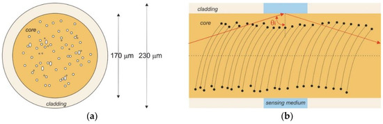
Figure 1.
(a) Schematic cross-section of the light-diffusing fiber (LDF) used for surface plasmon resonance (SPR) sensing; (b) Schematic lateral view of the LDF used for SPR sensing, showing the portion of unclad fiber.
For our tests, a 2 cm length of the fiber was unclad by means of a Miller stripping tool. In the first experimental configuration, one end of the fiber was coupled to the white light emitted by a tungsten halogen light source (HL2000, Ocean Optics), while the transmitted light was collected through a spectrophotometer with a detection range from 350 to 1023 nm (FLAME-S-VIS-NIR-ES, Ocean Optics). The outline of this sensor system (intensity-based LDF sensor) is shown in Figure 2a.
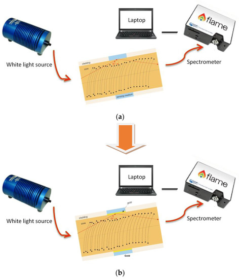
Figure 2.
Outline of the LDF sensor systems: (a) Intensity-based LDF sensor; (b) SPR-LDF sensor.
The SPR sensor was then obtained by depositing, through sputter coating (Bal-Tec SCD 500), a thin gold film over the same unclad portion of the LDF. Gold was chosen due to its high stability and ease of functionalization for biosensing applications. The sputtering process was repeated twice, upon rotating the fiber by 180°, in order to metalize the whole fiber circumference. The so-obtained gold film had a nominal thickness of 60 nm, and presented a good adhesion to the substrate, tested by its resistance to rinsing in de-ionized water. As shown in Figure 2b, the changes in the transmission spectrum induced by changes of the SRI have been recorded by using the same equipment previously described (halogen lamp and spectrometer).
3. Results and Discussion
As a first test, we have recorded the changes in the transmission spectrum of the fiber, with the uncoated fiber region immersed in water–glycerol mixtures with RI ranging from 1.332 to 1.443. From the measurements, it resulted that the external medium’s RI only influenced the total power transmitted through the LDF, while its spectral distribution kept constant. Therefore, we report in Figure 3a only the changes in the transmitted power, as a function of the SRI. We see that, for RI ranging from 1.332 to ~ 1.38 the transmitted power remained constant, while for RI larger than 1.38 the transmitted power dropped sensibly (ΔP~−4 dB when varying the RI from 1.332 to 1.443).
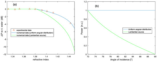
Figure 3.
(a) Variation of the transmitted power through the LDF as a function of the external medium’s RI. The continuous lines are the simulation results. (b) Angular distribution of optical power.
This behavior is consistent with a ray-optic description of light transmission through a multimode fiber [16]: as long as the external medium’s RI is lower than the cladding index (about 1.38 in our case), the power guided in the fiber is only affected by evanescent wave absorption (EWA), which is negligible in our case due to the short sensing region. Vice versa, when the RI of the external medium is situated between the cladding RI and the core RI, the variation in the transmitted power is mostly due to the reduction of the number of propagation modes satisfying the total internal reflection (TIR) condition at the boundary between the fiber core and the external medium (see Figure 1b). These arguments are confirmed by a numerical analysis carried out using the model described in Reference [17]: in brief, the normalized power transmitted over a sensing length is calculated by summing the power contributions over all the acceptance angles , where ) is the critical angle outside the sensing region. Assuming an unpolarized collimated light source, we can express the normalized transmitted power as [17]:
where is the initial power propagated by TIR, is the number of reflections, is the core diameter, and are the Fresnel reflectance coefficients at the boundary between the core and the sensing medium for p-polarization and s-polarization, respectively. As regards to the distribution of power among the various modes, the typical assumption about multimode fibers is a Lambertian source, which is actually the most accurate when the fiber is illuminated through a lens with a numerical aperture (NA) larger than that of the fiber. Under this assumption, the power distribution can be expressed as [17,18,19]:
From Figure 3, however, we see that the loss computed under the Lambertian source assumption does not match the experimentally observed behavior. Instead, an excellent agreement is found if assuming a perfectly scrambled angular distribution ( in Equation (1)). This finding is reasonable considering the scrambling of optical energy operated by the helical voids running along the core. To best illustrate this point, we compare in Figure 3b the angular distribution of power as expressed by Equation (2) (Lambertian source) with the one speculated for our LDF. It can be seen that, in the case of the Lambertian source, the power density of rays is higher near the critical angle ( in our case), therefore the loss of TIR for these rays, consequent to the increase of the SRI, has a greater impact on the transmitted power. Instead, for the scrambled, non-Lambertian case, power is equally distributed among the various angles; therefore, the relative weight of rays escaping away due to loss of TIR is lower.
After this preliminary study, we have used the SPR-based LDF sensor configuration. Figure 4a shows the experimental spectral transmission of our sensor, normalized to the spectrum recorded with air as the surrounding medium, for different water–glycerol solutions. A clear red-shift of the resonance wavelength (SPR dip) is observed when increasing the RI of the sensing medium. For comparison purposes, in Figure 4b we show the corresponding spectra obtained by using the same model previously described (Equation (1) with ), with the only difference that reflectance coefficients are now calculated taking into account the metal film.
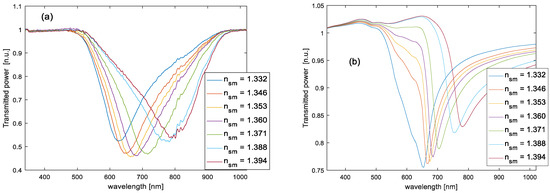
Figure 4.
Experimental (a) and numerical (b) SPR spectra obtained after normalization to the transmission spectrum in air.
In order to examine the obtained results, we recall some parameters, such as sensitivity and signal-to-noise ratio (SNR). The sensitivity (S) can be defined as the shift in resonance wavelength per unit change in refractive index [12,19,20,21,22]. It is usually reported in nanometers of peak shift per RI Unit (nm/RIU):
where is the SPR wavelength shift, and is the variation of refractive index of the sensing medium. Analogously, the SNR of an SPR sensor with spectral interrogation is a dimensionless parameter defined as [19]:
where is the SPR wavelength shift induced by a prescribed RI change, and is the spectral width of the SPR response curve corresponding to some reference level of the transmitted power [19]. From Figure 4 we see that, differently from the previous results, the agreement between experimental and numerical data is not excellent: in particular, the experimental spectra exhibit a deeper and wider resonance. Furthermore, the RI-induced SPR dip shift is larger in the experiments (173 nm in the analyzed range against a shift of 128 nm derived from simulations). In other words, the experimental sensitivity (S) is better than numerical sensitivity; vice versa, the SNR is worse. This discrepancy may be attributed to several reasons: first, some nonuniformity of the gold film thickness may exist along the length and/or circumference of the fiber; second, our model only takes into account meridional rays, while some skew rays may exist, especially if considering the influence of the scattering centers; third, the scattering of light due to the helicoid voids has been taken into account only partly in our model, in particular setting a uniform angular power distribution. However, the presence of the scattering centers could also affect the distribution of energy among p-polarization and s-polarization. Unfortunately, an accurate description of light scattering within the fiber core may be performed only if a statistical distribution of the helical voids were available, which was not our case. It is worth noting that, for , the experimental response indicates a resonance wavelength of ≈630 nm and a minimum transmittivity of ≈52%, while the corresponding numerical values are ≈650 nm and ≈75%, respectively. As discussed in Reference [23], the propagation of skew rays leads to a downward, as well as a backward, shift in the SPR curve, which is consistent with our observations and suggests a major influence of skew rays, compared to a conventional multimode fiber.
Finally, Figure 5 shows the experimentally obtained resonance wavelength versus the SRI, together with the results of a quadratic fitting. From Figure 5, we see that the sensitivity is not constant, increasing from ≈1500 to ≈4000 nm/RIU in the analyzed range.
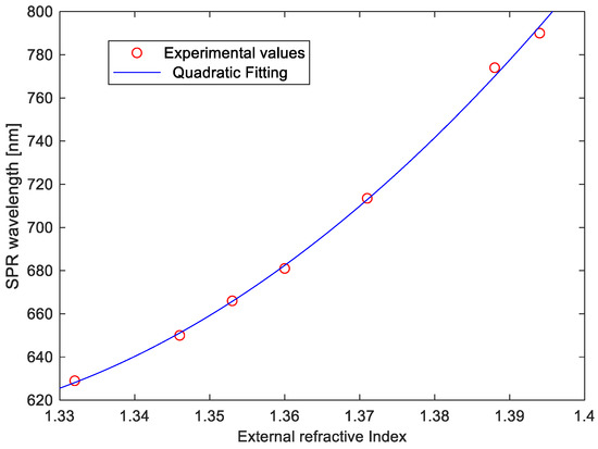
Figure 5.
SPR wavelength as a function of the SRI. The circles are extracted from experimental data, while the continuous line is the quadratic fitting curve.
Several comparative analyses between different fiber-optic-based SPR sensor configurations (D-shaped fibers, tapered fibers, single-mode fibers, U-shaped fibers, TFBGs fibers, heterocore fibers, etc.) can be found in excellent review papers [4,5,24]. Here, we just compare the performance of our sensor with those of a similar SPR sensor configuration based on an HCS optical fiber (FT300EMT from Thorlabs) [19]. In that paper, a very similar setup based on a tungsten halogen light source and a spectrophotometer was used to characterize the sensor. The HCS sensor presented in Reference [19] had a length of 2 cm, a core and cladding diameter of 300 and 330 µm, respectively, and was coated with a thin gold film. We compare in Table 1 the performance of our LDF-based SPR sensor with those of the HCS sensor as extracted from Reference [19] for two refractive indices of interest (1.367 and 1.384). These values have been chosen as they are typical of biosensors based on bioreceptors with analytes in water solution (≈1.36), and of chemical sensors based on thin films of polymer receptors with compounds in water solution (≈1.38). Furthermore, the parameter appearing in Equation (4) has been chosen in relation to , while the was taken at the middle level between the maximum and minimum power.

Table 1.
Comparison of performance of two different SPR multimode optical fiber sensors for two refractive indices (1.367 and 1.384).
Table 1 shows that the sensitivity of the LDF sensor is better than the HCS sensor; vice versa, the SNR is worse. We emphasize that the HCS sensor chosen for comparison had a core diameter (300 µm) larger than our LDF (170 µm), and that, in general, the performance of SPR sensors based on multimode fibers improve with the diameter of the fiber [20]. We argue that the LDF sensor has a higher sensitivity compared to the HCS due to a higher number of modes internally excited by the nanovoids. Similarly, the increased modal content may also explain the higher FWHM of the SPR response. However, a more extensive analysis of the modal distribution inside the LDF must be carried out in order to fully explain the obtained results.
4. Conclusions
An LDF has been proposed as host material for SPR-based refractive index sensing. The realized SPR sensor shows a high sensitivity to the external refractive index (about 4000 nm/RIU for an SRI of 1.394). A tentative model has been developed in terms of power distribution within the fiber, which has been shown to accurately describe the changes of transmitted power along an unclad LDF. The proposed sensor does not require any specific processing of the fiber, apart from a metallization of the probe region, and exhibits a better sensitivity than similar SPR sensors based on a multimode optical fiber. In contrast, the SNR is lower than the HCS fiber, and much lower than single-mode fiber SPR sensors. However, we believe that the observed SNR is still sufficient to allow biochemical applications as demonstrated in the literature with other multimode SPR configurations. The sensor is easily repeatable, disposable, free of labeling, and has a potential for real-time detection, so it is ideally suited for biochemical sensing and environmental monitoring.
Author Contributions
N.C., L.Z. and A.M. conceived, designed and realized the SPR sensor device. All the authors realized the experimental measurements, analyzed the results and contributed to the writing of paper.
Funding
This research received no external funding.
Conflicts of Interest
The authors declare no conflicts of interest.
References
- Homola, J. Present and future of surface plasmon resonance biosensors. Anal. Bioanal. Chem. 2003, 377, 528–539. [Google Scholar] [CrossRef] [PubMed]
- Homola, J.; Yee, S.S.; Gauglitz, G. Surface plasmon resonance sensors: Review. Sens. Actuators B Chem. 1999, 54, 3–15. [Google Scholar] [CrossRef]
- Liu, Y.; Liu, Q.; Chen, S.; Cheng, F.; Wang, H.; Peng, W. Surface Plasmon Resonance Biosensor Based on Smart Phone Platforms. Sci. Rep. 2015, 5, 12864. [Google Scholar] [CrossRef] [PubMed]
- Caucheteur, C.; Guo, T.; Albert, J. Review of plasmonic fiber optic biochemical sensors: Improving the limit of detection. Anal. Bioanal. Chem. 2015, 407, 3883–3897. [Google Scholar] [CrossRef] [PubMed]
- Klantsataya, E.; Jia, P.; Ebendorff-Heidepriem, H.; Monro, T.M.; François, A. Plasmonic fiber optic refractometric sensors: From conventional architectures to recent design trends. Sensors 2017, 17, 12. [Google Scholar] [CrossRef] [PubMed]
- Anuj, K.; Sharma, R.J.; Gupta, B.D. Fiber-optic sensors based on surface Plasmon resonance: A comprehensive review. IEEE Sens. J. 2007, 7, 1118–1129. [Google Scholar]
- Trouillet, A.; Ronot-Trioli, C.; Veillas, C.; Gagnaire, H. Chemical sensing by surface plasmon resonance in a multimode optical fiber. Pure Appl. Opt. 1996, 5, 227–237. [Google Scholar] [CrossRef]
- Pollet, J.; Delport, F.; Janssena, K.P.F.; Jans, K.; Maes, G.; Pfeiffer, H.; Wevers, M.; Lammertyn, J. Fiber optic SPR biosensing of DNA hybridization and DNA–protein interactions. Biosens. Bioelectron. 2009, 25, 864–869. [Google Scholar] [CrossRef] [PubMed]
- Masson, J.F.; Kim, Y.C.; Obando, L.A.; Peng, W.; Booksh, K.S. Fiber-optic surface plasmon resonance sensors in the near-infrared spectral region. Appl. Spectrosc. 2006, 60, 1241–1246. [Google Scholar] [CrossRef] [PubMed]
- Slavik, R.; Homola, J.; Ctyroky, J. Single-mode optical fiber surface plasmon resonance sensor. Sens Actuators B Chem. 1999, 54, 74–79. [Google Scholar] [CrossRef]
- Jorgenson, R.C.; Yee, S.S. A fiber-optic chemical sensor based on surface plasmon resonance. Sens. Actuators B Chem. 1993, 12, 213–220. [Google Scholar] [CrossRef]
- Cennamo, N.; Massarotti, D.; Conte, L.; Zeni, L. Low Cost Sensors Based on SPR in a Plastic Optical Fiber for Biosensor Implementation. Sensors 2011, 11, 11752–11760. [Google Scholar] [CrossRef] [PubMed]
- Liang, G.; Luo, Z.; Liu, K.; Wang, Y.; Dai, J.; Duan, Y. Fiber Optic Surface Plasmon Resonance–Based Biosensor Technique: Fabrication, Advancement, and Application. Crit. Rev. Anal. Chem. 2016, 46, 213–223. [Google Scholar] [CrossRef] [PubMed]
- Galatus, R.; Farago, P.; Cennamo, N.; Cristea, C.; Feier, B. SPR based hybrid electro-optic biosensor platform: SPR-cell with side emitting plastic optical fiber. In Proceedings of the 2017 IEEE 23rd International Symposium for Design and Technology in Electronic Packaging (SIITME), Constanta, Romania, 26–29 October 2017; pp. 328–331. [Google Scholar]
- Logunov, S.; Fewkes, E.; Shustack, P.; Wagner, F. Light Diffusing Optical Fiber for Illumination. In Renewable Energy and the Environment; Paper DT3E.4; OSA Technical Digest (online), Optical Society of America: Washington, DC, USA, 2013. [Google Scholar]
- Apriyanto, H.; Ravet, G.; Bernal, O.D.; Cattoen, M.; Seat, H.C.; Chavagnac, V.; Surre, F.; Sharp, J.M. Comprehensive Modeling of Multimode Fiber Sensors for Refractive Index Measurement and Experimental Validation. Sci. Rep. 2018, 8, 5912. [Google Scholar] [CrossRef] [PubMed]
- Sharma, A.K.; Gupta, B.D. Absorption-based fiber optic surface plasmon resonance sensor: A theoretical evaluation. Sens. Actuators B Chem. 2004, 100, 423–431. [Google Scholar] [CrossRef]
- Sequeira, F.; Duarte, D.; Bilro, L.; Rudnitskaya, A.; Pesavento, M.; Zeni, L.; Cennamo, N. Refractive Index Sensing with D-Shaped Plastic Optical Fibers for Chemical and Biochemical Applications. Sensors 2016, 16, 2119. [Google Scholar] [CrossRef] [PubMed]
- Kanso, M.; Cuenot, S.; Louarn, G. Sensitivity of optical fiber sensor based on surface plasmon resonance: Modeling and experiments. Plasmonics 2008, 3, 49. [Google Scholar] [CrossRef]
- Dwivedi, Y.S.; Sharma, A.K.; Gupta, B.D. Influence of design parameters on the performance of a surface plasmon sensor based fiber optic sensor. Plasmonics 2008, 3, 79. [Google Scholar] [CrossRef]
- Iga, M.; Seki, A.; Watanabe, K. Gold thickness dependence of SPR-based hetero-core structured optical fiber sensor. Sens. Actuators B Chem. 2005, 106, 363. [Google Scholar] [CrossRef]
- Sharma, A.K.; Gupta, B.D. On the sensitivity and signal to noise ratio of a step-index fiber optic surface plasmon resonance sensor with bimetallic layers. Opt. Commun. 2005, 245, 159–169. [Google Scholar] [CrossRef]
- Yogendra, S.D.; Sharma, A.K.; Gupta, B.D. Influence of skew rays on the sensitivity and signal-to-noise ratio of a fiber-optic surface-plasmon-resonance sensor: A theoretical study. Appl. Opt. 2007, 46, 4563–4569. [Google Scholar]
- Gupta, B.D.; Kant, R. Recent advances in surface plasmon resonance based fiber optic chemical and biosensors utilizing bulk and nanostructures. Opt. Laser Technol. 2018, 101, 144–161. [Google Scholar] [CrossRef]
© 2018 by the authors. Licensee MDPI, Basel, Switzerland. This article is an open access article distributed under the terms and conditions of the Creative Commons Attribution (CC BY) license (http://creativecommons.org/licenses/by/4.0/).