Article

Ultrathin Microwave Devices for Polarization-Dependent Wavefront Shaping Based on an Anisotropic Metasurface

School of Computer and Information, Hefei University of Technology, Hefei 230009, China
*
Author to whom correspondence should be addressed.
Appl. Sci. 2018, 8(12), 2471; https://doi.org/10.3390/app8122471
Submission received: 7 November 2018 / Revised: 30 November 2018 / Accepted: 30 November 2018 / Published: 3 December 2018
(This article belongs to the Special Issue Metamaterials and Transformation Optics)

Abstract

:

Featured Application

The proposed approach may pave a way towards the practical applications of metasurfaces in the microwave band.

Abstract

Metasurfaces have recently become a promising material, offering new degrees of freedom in molding electromagnetic wave properties. In this work, we propose and numerically investigate ultrathin microwave devices for polarization-dependent wavefront shaping based on an anisotropic metasurface, which consists of a square metal ring with a cross, a dielectric substrate, and a metal ground plane. It is demonstrated the proposed metasurface can independently manipulate reflective x- and y-polarized wavefronts at frequency of 15 GHz via engineering of the metal cross. Furthermore, the reflective efficient is extremely high, reaching a near-unity value of 0.98. Based on this anisotropic metasurface, a polarization beam splitter is achieved by artificially arranging the spatial distribution of metasurfaces with prescribed geometries. In addition, we successfully design a focusing metasurface to separate the x- and y-polarized beams via focusing them at different positions. The proposed approach paves a way toward the applications of the metasurface in a microwave band.

1. Introduction

Metamaterials have attracted a growing amount of attention for their fascinating physical properties [1,2], which could be utilized in research and practical applications. Currently, wavefront manipulation based on metamaterials has become a hot research area, due to their artificial engineered properties and small sizes. However, wavefront engineering based on multilayered three dimensional metamaterials suffers from many drawbacks [1,2,3,4], such as low efficiency and costly fabrication, restricting its development and application. To overcome these drawbacks, metasurfaces [5,6,7], a kind of 2D metamaterial, have been introduced, by arranging an array of periodic and quasi-periodic subwavelength antennas on a planar substrate to generate abrupt phases or amplitudes of the incident wave.
Based on this concept, many metasurfaces have been proposed to obtain various kinds of wavefront shaping, including anomalous refraction [8], reflection [9], vortex wave generation [10,11,12], and focusing [13,14,15]. These metasurfaces can be classified into two categories, according to their working mechanisms. The first is transmissive metasurfaces [16,17,18], where the efficiency is a major concern, due to the intrinsic absorption loss in materials. The second is reflective metasurface [19,20], which could avoid absorption and usually exhibit a higher efficiency. In 2011, Yu et al. firstly utilized a V-shaped antenna to realize an anomalous reflection based on a phase gradient metasurface [21]. Following their pioneering work, researchers have devoted extensive efforts into developing reflective metasurfaces with tailored phase distributions for wavefront shaping [22,23,24,25,26,27,28,29]. However, most of the previous investigations focus on the isotropic reflective metasurface, hindering the application of metasurfaces in the manipulation of light with different polarizations. Therefore, several anisotropic metasurfaces have been demonstrated to tailor the reflective wavefront under illumination with different polarizations in visible, infrared, and THz regions [30,31,32]. More recently, researchers have brought the anisotropic reflective metasurface into the microwave regime to realize the polarization-dependent manipulation of microwaves for wireless communication [33].
In this work, an ultrathin anisotropic reflective metasurface is proposed to independently control the wavefront of x- and y-polarized waves at a frequency of 15 GHz, with high efficiency. The anisotropic metasurface is composed of three layers, including a square metal ring with a cross resonator, a dielectric substrate, and a metal ground. The anisotropic responses for reflective x- and y-polarized waves are realized by engineering the geometry of the metallic cross resonator. Based on this anisotropic metasurface, a pure polarization beam splitter can be achieved under a quasi-plane wave incidence. Moreover, the principle of the independent manipulation of x- and y-polarized microwaves is extended to focusing x- and y-polarized components to different positions. The simulation results are in good agreement with the theoretical design. The proposed anisotropic metasurface may have great prospects in the practical application of microwave antennas.

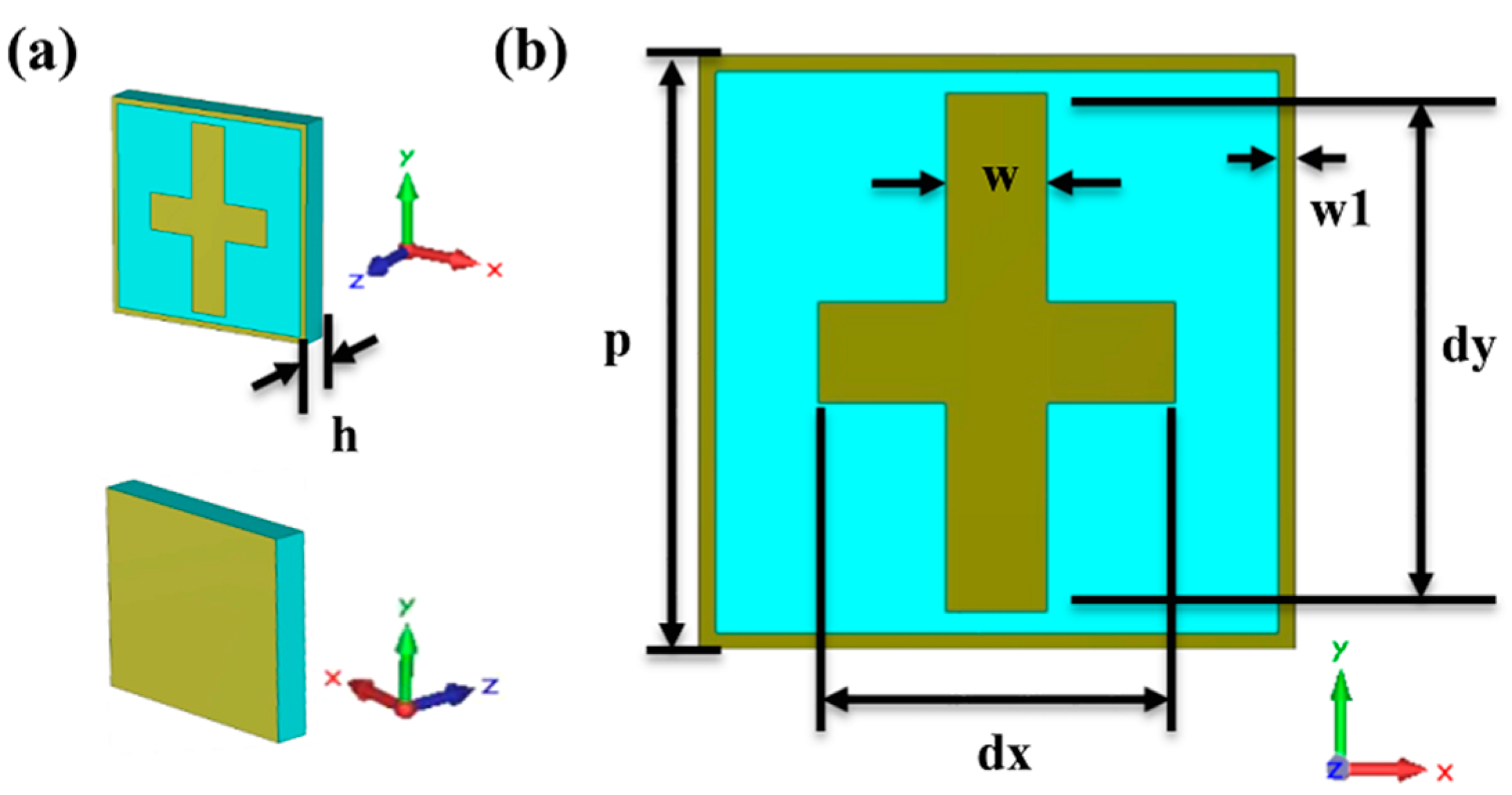
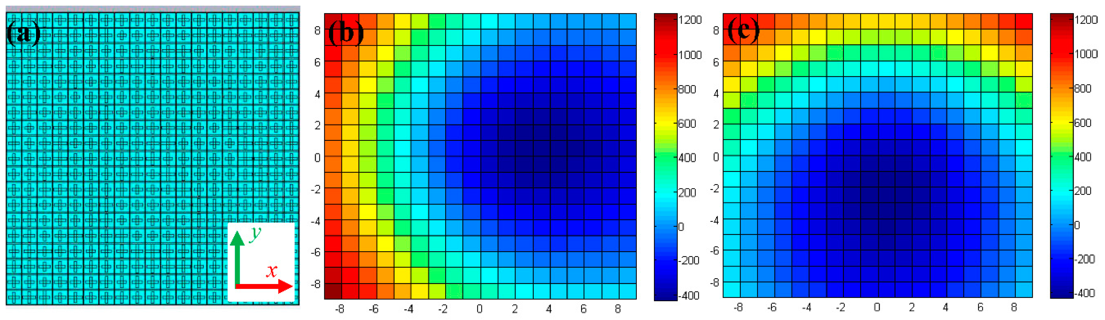
2. Design Principle and Simulation Method

To illustrate the design principle of our approach, Figure 1 schematically shows a unit cell of the proposed anisotropic metasurface, which is composed of a square metal ring with a cross resonator, a dielectric substrate, and a back metal-ground. The square metal ring is used to modulate the phase response of the unit cell to cover a wide range. The metal cross resonator is designed to control the phase of x- and y-polarized reflections independently by varying the geometric sizes of the transverse and vertical rods, respectively. The dielectric substrate sustains the metal ring and the cross resonator. The metal-ground is used to effectively reflect microwave back to free space. The top and bottom panels of Figure 1a are the perspective views of the unit cell from the front and back, respectively. Figure 1b shows the detailed front view of a unit cell with geometrical parameters.
A numerical simulation is performed by using CST Microwave Studio (2015, CST China Ltd., Shanghai, China). The period boundary condition and the absorbing boundary condition are set in the x/y and z directions to save memory, and to reduce simulation time, respectively. The unit cell is illuminated by a plane wave propagating along the backward direction (from +z to −z) with x- and y-polarization. To acquire a wide phase coverage (at least 280°), the geometrical parameters are optimized, and ultimately listed as follows: p = 7 mm, w = 1.2 mm, w1 = 0.2 mm. The thickness of the proposed unit cell h is 1 mm, and approximately equal to 1/20 of the wavelength, at a frequency of 15 GHz. The dielectric substrate is set as FR4, with a relative permittivity of 4.3 and a loss tangent of 0.001 [31]. The metal is approximately set as a perfect electric conductor (PEC) for simulation convenience. The incident microwave source is a plane wave propagating along the z-axis with x/y polarization.
To demonstrate the anisotropic response of the unit cell for different polarized incident microwaves, Figure 2 shows the reflective coefficient S11 of the proposed metasurface at a frequency of 15 GHz as a function of dx and dy. Figure 2a,b shows the amplitude and phase of S11 under x-polarized incidence, with dx and dy varying from 4 mm to 6.5 mm, respectively. The results indicate a large amplitude over 0.98, and a phase shift of about 320° with varying dx, while S11 is independent on dy. Figure 2c,d shows the amplitude and phase of S11 under y-polarized incidence, with dx and dy varying from 4 mm to 6.5 mm, respectively. It is shown that the dependence of S11 under y-polarized incidence on dx and dy is similar to that of under x-polarized on dy and dx, respectively, due to the symmetry of the proposed metasurface. Overall, the local phase for x- and y-polarized microwaves can be independently tailored by controlling the geometrical parameters, which is called the double-phase modulating mechanism.
As mentioned above, the square metal ring could increase the coverage of the phase response of the unit cell. To demonstrate, the amplitude and phase of reflective coefficient S11 for the unit cell with and without the square ring are compared in Figure 3. Here, dy is fixed 4.5 mm and dx is varying from 4 mm to 6.5 mm. Figure 3a,c shows that the reflective amplitude is always over 0.98 with and without the square ring, respectively, indicating the proposed structure is high efficiently. Figure 3b shows that the phase shift of S11 for the proposed structure under x-polarized incidence covers a broad angle range of 320° (from −45° to −365°). In contrast, Figure 3d shows that the phase shift of S11 for the structure without the square ring merely covers an angle range of 300° (from −63.9° to −365°) under x-polarized incidence. For the cases under y-polarized incidence (red lines), both the amplitude and phase are independent on dx. In addition, it is easy to understand that the dependence of phase shift on dy is opposite, due to the structural symmetry. Therefore, these results clearly demonstrate that the metal square ring can effectively extend the ability of the proposed structure to manipulate the reflective phase.
Note that, the reflective phase covers only 320°, and it cannot reach a perfect coverage of 360°. To minimize the deviation during the metasurface design, we can choose the cell with a relative phase of 320° and 360° (0°) to approximate that with a phase of 320°~340° and 340°~360°, respectively. According to the analysis above, it can be concluded that the anisotropic metasurface cell can be used to manipulate the wavefront of the x- and y-polarized waves independently, by changing the geometric parameters of dx and dy, respectively. In the following, we will manifest the proposed metasurface as a good candidate for polarization-dependent wavefront shaping by investigating two proof-of-concept examples, i.e., a reflective polarization beam splitter and a focusing lens.

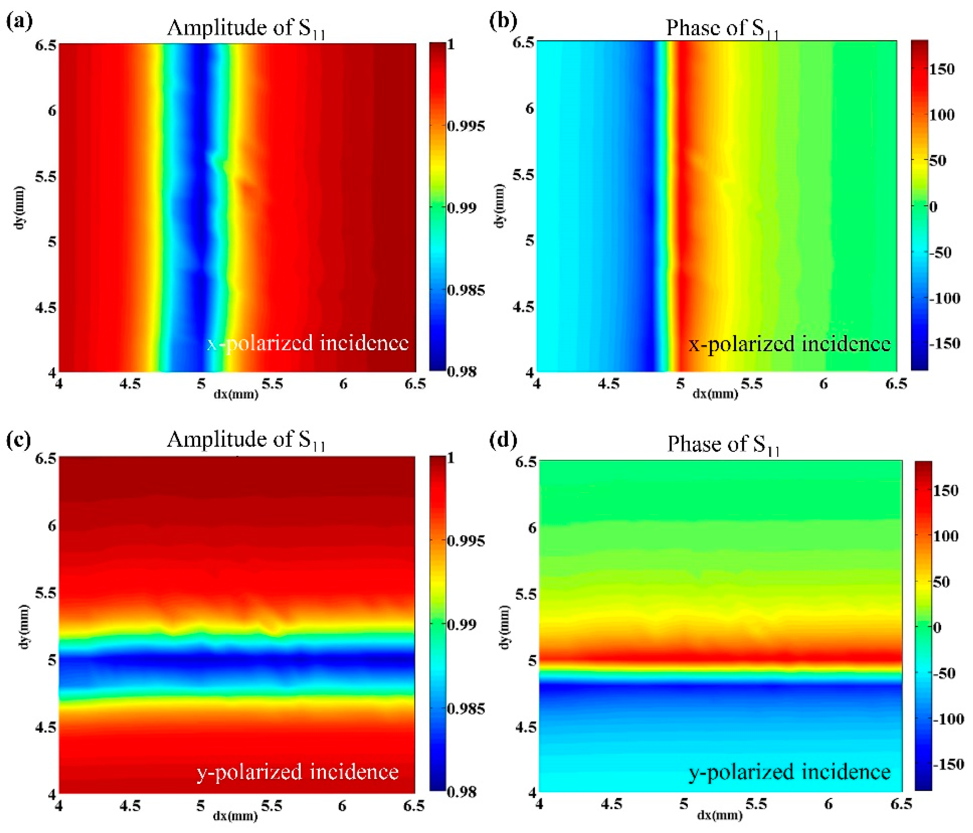
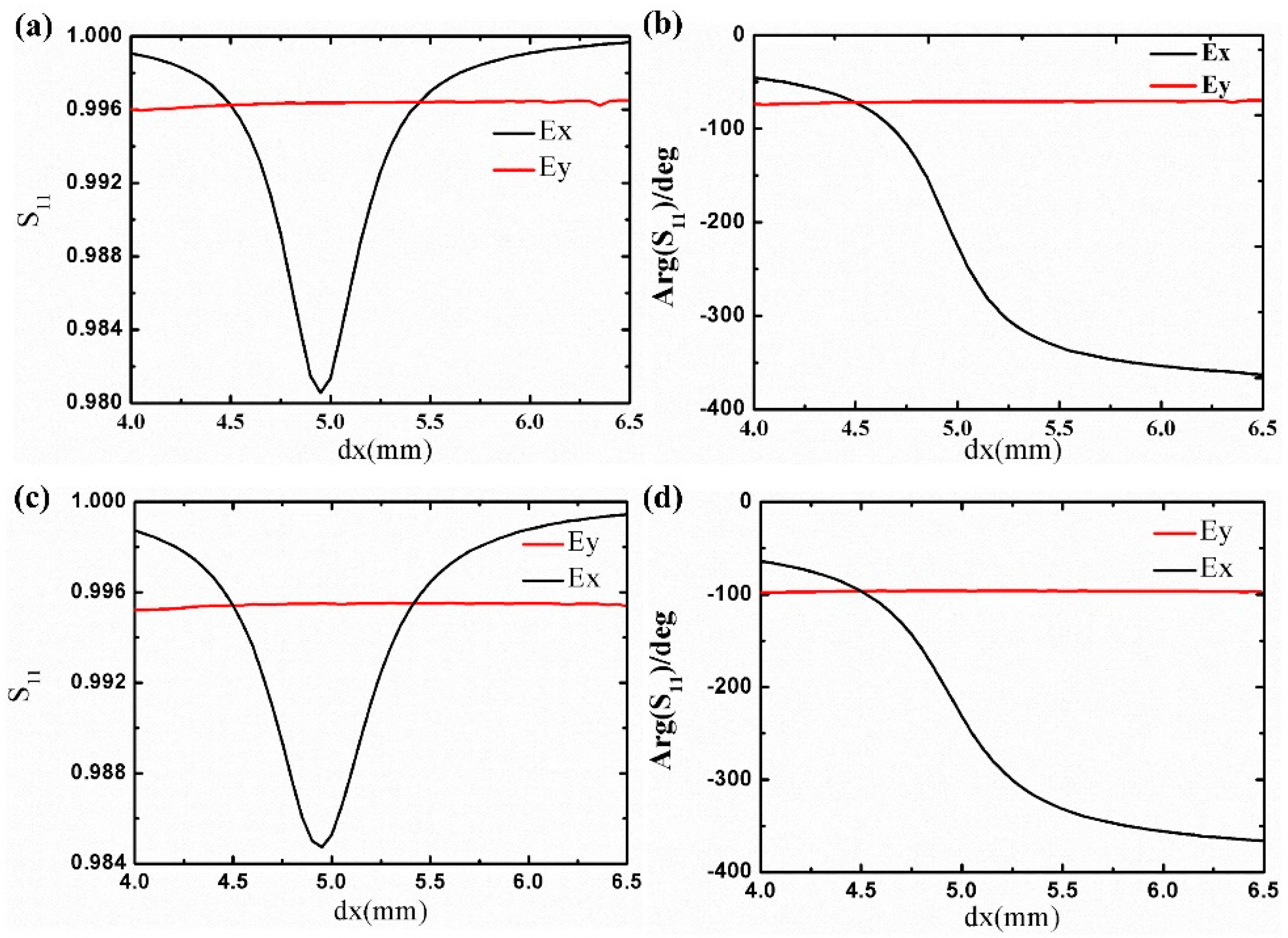
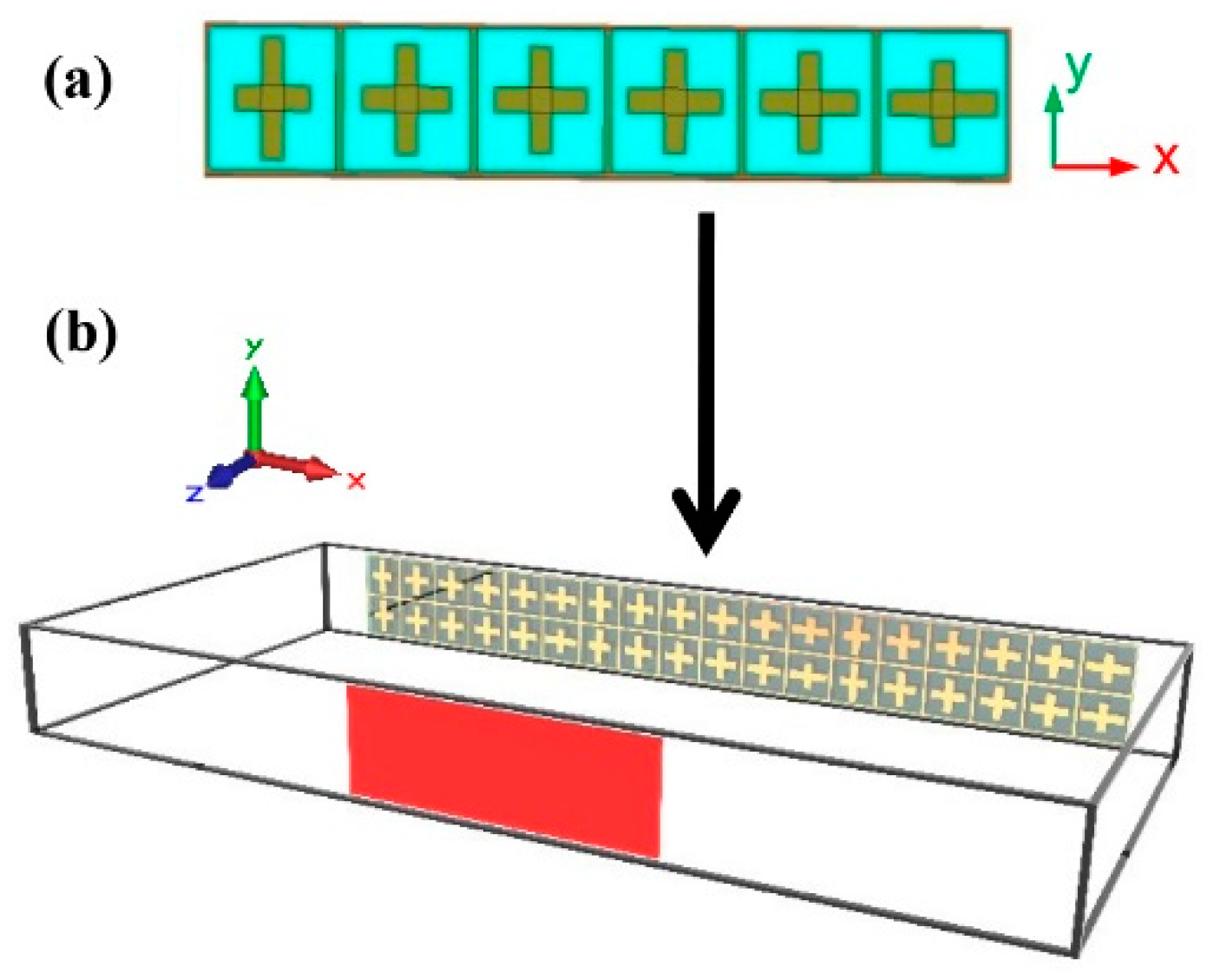
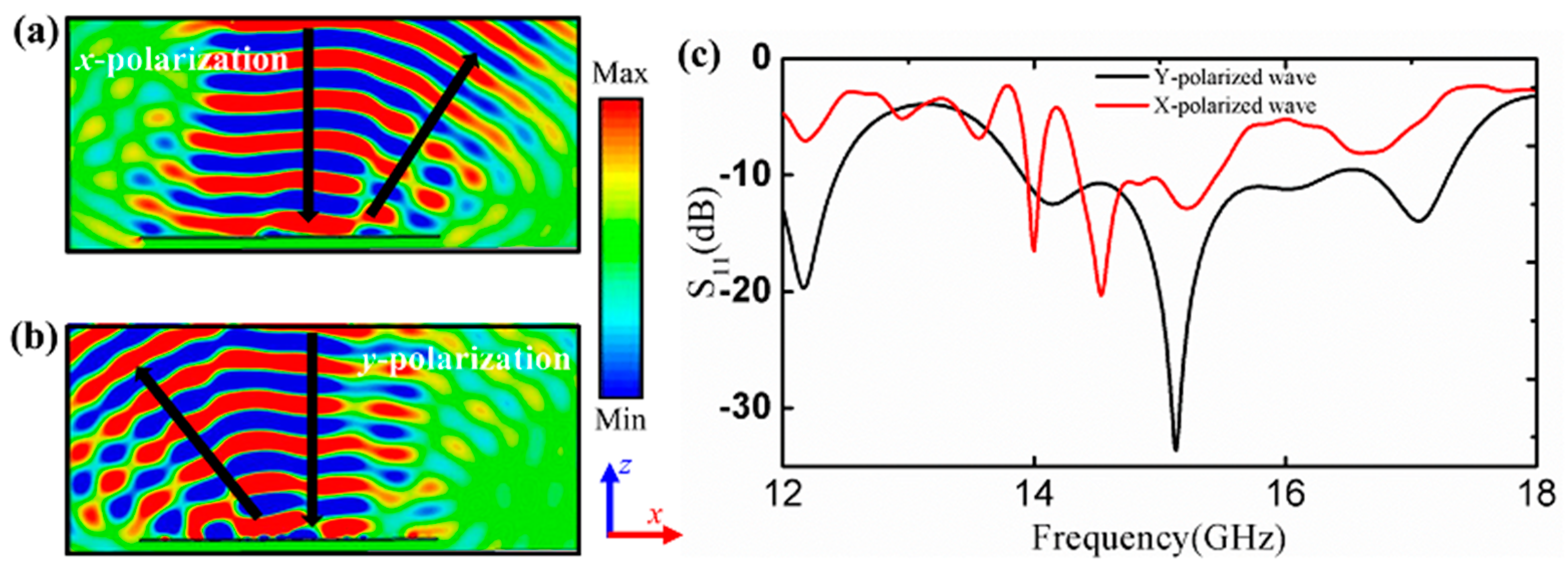
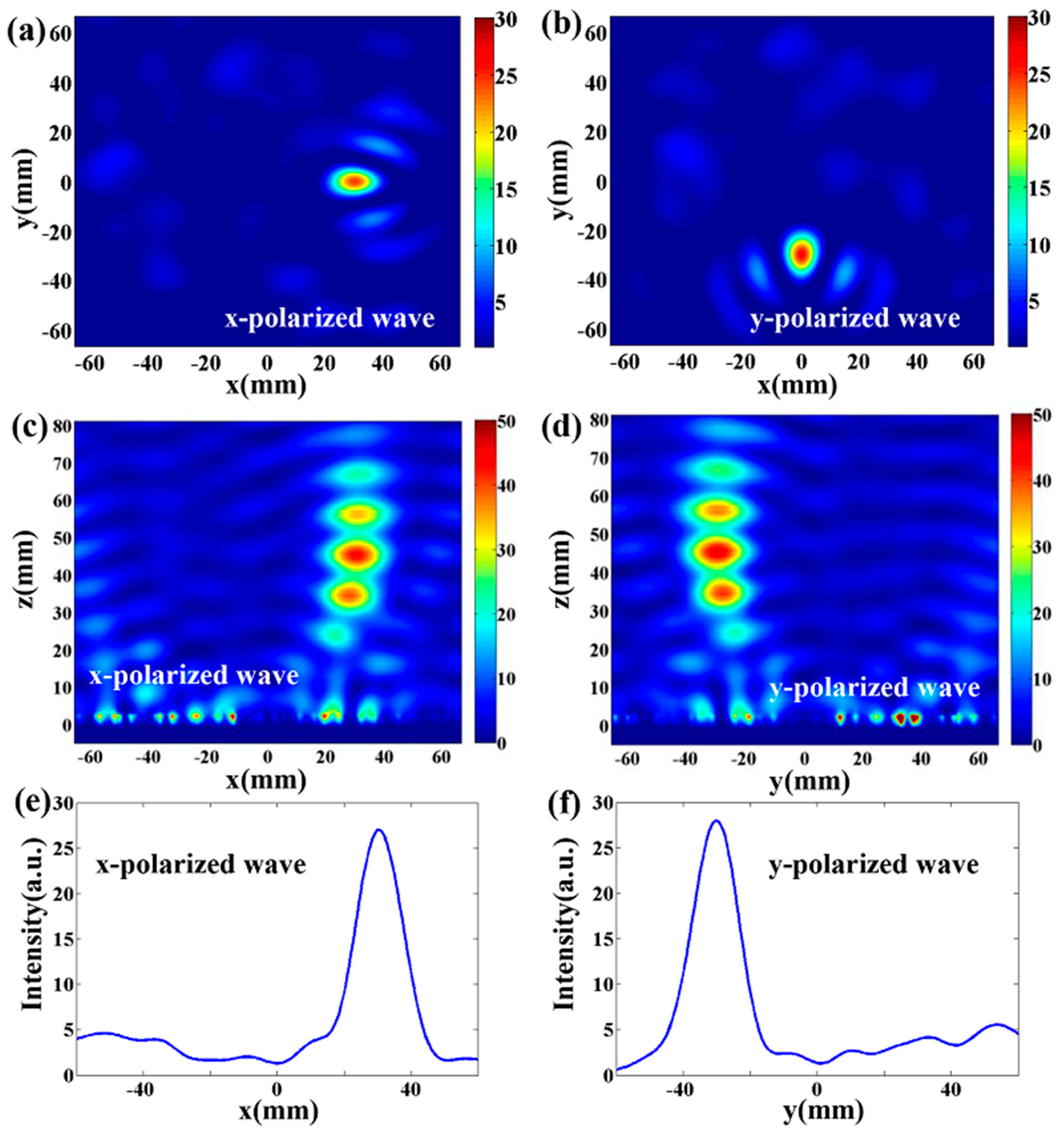
3. Results and Discussion

Based on the proposed anisotropic metasurface, a linear polarization beam splitter is firstly designed to independently deflect x- and y-polarized waves at opposite oblique angles of −28.4° and 28.4° in the xz plane, by engineering the phase gradient along the x-direction, respectively. As is well known, for a surface with phase gradient of Φ / x along the interface, the reflected beam can be described by generalized Snell’s law, as follows [2]:
sin θ r sin θ i = λ 0 2 π n i Φ x
where θ r and θ i are the angles of reflection and incidence, respectively. λ 0 is the incident wavelength in a vacuum. n i is the refractive index of the incidence space, which equals 1 in our case. Therefore, we select six cells with different geometric parameters to satisfy the phase gradient, achieving linear polarization beam splitting. Table 1 summarizes the sizes and phase distributions of the six unit cells along the x-axis, where n is the number of the unit cell, and Φ x and Φ y are the phase response of the cells for incident x- and y-polarized waves, respectively. The phase gradient for x- and y-polarization are −60° and 60°, therefore resulting in reflection angles of −28.4° and 28.4°, respectively. In addition, for the sake of a better result, we design a beam splitter consisting of 3 × 2 element arrays of the supercell. Figure 4a,b schematically shows the supercell and the prospect view of our designed beam splitter, respectively. To simulate, the periodic boundary condition is set only in the y direction, while the open boundary condition is used in both x and z directions [31]. The incidence is set as a waveguide port, irritating the quasi-plane wave.
To depict the phenomenon of the polarization beam splitting, the near-field distributions of the electric field for the x- and y-polarized waves are plotted in Figure 5a,b, respectively. Both polarization components are not reflected normally, but at an oblique angle of −28.4° and 28.4° for the x- and y-polarized waves, respectively. This is in a good agreement with the theoretical value of generalized Snell’s law. In addition, the return loss of the polarization beam splitter at the incident port is shown in Figure 5c, presenting the dips lying at around 15 GHz for both the x- and y-polarized waves. It indicates that the energy is deflected at oblique angles, and it does not return to the incident port. Thus, it is further demonstrated in that the anisotropic metasurface has a great potential in the application of microwave polarization manipulation. It should be noted that the deviation of the simulated x-polarized wave from the theoretical design results from the coupling along the x-axis between the neighboring unit cells.
Based on the results above, we additionally design a polarization-dependent focusing metasurface to focus on the x- and y-polarized waves at different positions. By employing the proposed structure, metasurfaces with a hyperboloidal phase distribution can tailor the reflective wavefront and convert the spherical wave to a plane wave, or focus the plane wave at a point. It is widely known that the hyperboloidal phase distribution based on Fermat’s principle can be described as follows [31]:
φ ( x , y ) = 2 π λ 0 ( x 2 + y 2 + L 2 L ) + φ 0
where λ 0 and L are the incident wavelength and focal length, respectively; φ ( x , y ) and φ 0 are the phase in the arbitrary position (x, y) and the original phase on the metasurface, respectively. To achieve polarization-dependent focusing, different hyperboloidal phase distributions need to be arranged for x- and y-polarized waves, as shown below [31].
φ x ( x , y ) = 2 π λ ( x 2 + y 2 + L 2 L ) + ξ 1 · x + φ 0
φ y ( x , y ) = 2 π λ ( x 2 + y 2 + L 2 L ) + ξ 2 · y + φ 0
where ξ 1 and ξ 2 are extra linear-phase gradient responses along the x- and y-directions, to enable anomalous focusing for incident x- and y-polarized waves, respectively. φ x ( x , y ) and φ y ( x , y ) are the rearranged phase distributions at the metasurface for the incident x- and y-polarized waves, respectively. From Equations (5) and (6), if the incidence is a plane wave with both the x/y-components, it can be converted to spherical waves and focused at the target spot for x/y-polarization. Based on the designing principle, we artificially engineer different hyperbolical phase profiles for x/y-polarized waves on the metasurface by 19 × 19 cells, as schematically presented in Figure 6a. In addition, the phase distributions for the x- and y-polarized waves is plotted in Figure 6b,c, respectively. In these designs, we set the focal length L = 40 mm, φ 0 = −345.6°, and the incident wavelength λ = 20 mm. The phase gradient ξ 1 and ξ 2 are set as − π / ( 3 p ) and π / ( 3 p ) , respectively. Thus, the position of the designed focusing metasurface is (22, 0) and (0, −22) mm for the x- and y-polarized waves, respectively.
To investigate the polarization-dependent focusing ability, we perform numerical simulations by using CST Microwave Studio, where the absorbing boundary condition was applied at all boundaries. Figure 7a,b shows the near-field distributions of electric intensity in the xy plane for the x- and y-polarized waves, respectively, demonstrating a perfect polarization-dependent focusing effect. In addition, Figure 7c,d are the near-field distributions of electric intensity in the xz and yz planes for the x- and y-polarized waves, respectively. The position of the deflective focusing spot in the xy plane (z = 40 mm) is approximately (29, 0) and (0, −29) mm for the x- and y-polarized waves, respectively. The difference in the focusing position between the theory and simulation is attributed to a phase convergence of merely 320° and the coupling effect between neighboring unit cells. To some extent, the simulation results agree well with the theoretical result. Figure 7e,f plots the extract field intensity at the focal plane along the x- and y-axis, respectively, further verifying the ability of the polarization-dependent wavefront shaping of the proposed metasurface.

4. Conclusions

In conclusion, we have numerically proposed an ultra-thin anisotropic metasurface for polarization-dependent wavefront shaping at a frequency of 15 GHz in the microwave range. All simulations have been performed by using CST Microwave Studio. We have first demonstrated that the response of the proposed metasurface for orthogonal polarized waves can be independently manipulated at a frequency of 15 GHz with high efficiency via engineering of the geometric parameters of the metal cross. In addition, two proof-of-concept examples have been designed and investigated. First, a polarization beam splitter has been achieved under the excitation of the waveguide port. Second, polarization-dependent focusing based on an anisotropic metasurface has been also investigated. The proposed design paves the way for the design of efficient metasurfaces in microwave applications and wireless communication.

Author Contributions

Conceptualization, methodology, software, writing—original draft preparation, contributed by K.G. and Z.G.; writing—review and editing, and supervision, contributed by Z.G.

Funding

This research was funded by the National Natural Science Foundation of China, grant numbers 61775050, 11804073, Natural Science Foundation of Anhui Province, China, grant number 1808085QA21, and Fundamental Research Funds for the Central Universities, grant numbers JD2017JGPY0005, JZ2018HGBZ0309 and JZ2018HGTB0240.

Conflicts of Interest

The authors declare no conflict of interest.

References

  1. Shelby, R.A.; Smith, D.R.; Schultz, S. Experimental verification of a negative index of refraction. Science 2001, 292, 77–79. [Google Scholar] [CrossRef] [PubMed]
  2. Sihvola, A. Metamaterials in electromagnetics. Metamaterials 2007, 1, 2–11. [Google Scholar] [CrossRef]
  3. Shamonian, E.; Solymar, L. Metamaterials: How the subject started. Metamaterials 2007, 1, 12–18. [Google Scholar] [CrossRef]
  4. Cai, W.; Chettiar, U.K.; Kildishev, A.V.; Shalaev, V.M. Optical cloaking with metamaterials. Nat. Mater. 2007, 1, 224–227. [Google Scholar] [CrossRef] [Green Version]
  5. Ni, X.; Emani, N.K.; Kildishev, A.V.; Boltasseva, A.; Shalaev, V.M. Broadband light bending with plasmonic nanoantennas. Science 2012, 335, 427. [Google Scholar] [CrossRef]
  6. Bohn, B.J.; Schness, M.; Kats, M.A.; Aieta, F.; Hillenbrand, R.; Capasso, F. Near-field imaging of phased array metasurfaces. Nano. Lett. 2015, 15, 3851–3858. [Google Scholar] [CrossRef]
  7. Zhang, X.; Tian, Z.; Yue, W.; Gu, J.; Zhang, S.; Han, J.; Zhang, W. Broadband terahertz wave deflection based on C-shape complex metamaterials with phase discontinuities. Adv. Mater. 2013, 25, 4567–4572. [Google Scholar] [CrossRef]
  8. Grady, N.K.; Heyes, J.E.; Chowdhury, D.R.; Zeng, Y.; Reiten, M.T.; Azad, A.K.; Taylor, A.J.; Dalvit, D.A.; Chen, H.T. Terahertz metamaterials for linear polarization conversion and anomalous refraction. Science 2013, 340, 1304–1307. [Google Scholar] [CrossRef]
  9. Ma, H.F.; Wang, G.Z.; Kong, G.S.; Cui, T.J. Independent controls of differently-polarized reflected waves by anisotropic metasurfaces. Sci. Rep. 2015, 5, 9605. [Google Scholar] [CrossRef]
  10. Wang, W.; Guo, Z.Y.; Sun, Y.X.; Shen, F.; Li, Y.; Liu, Y.; Wang, X.S.; Qu, S.L. Ultra-thin optical vortex phase plate based on the L-shaped nanoantenna for both linear and circular polarized incidences. Opt. Commun. 2015, 355, 321–325. [Google Scholar] [CrossRef]
  11. Mehmood, M.Q.; Mei, S.; Hussain, S.; Huang, K.; Siew, S.Y.; Zhang, L.; Zhang, T.; Ling, X.; Liu, H.; Teng, J.; et al. Visible-frequency metasurface for structuring and spatially multiplexing optical vortices. Adv. Mater. 2016, 28, 2533–2539. [Google Scholar] [CrossRef] [PubMed]
  12. Li, Z.; Palacios, E.; Butun, S.; Aydin, K. Visible-frequency metasurfaces for broadband anomalous reflection and high-efficiency spectrum splitting. Nano Lett. 2015, 15, 1615–1621. [Google Scholar] [CrossRef] [PubMed]
  13. Wang, W.; Guo, Z.; Zhou, K.; Sun, Y.; Shen, F.; Li, Y.; Qu, S.; Liu, S. Polarization-independent longitudinal multi-focusing metalens. Opt. Express 2015, 23, 29855–29866. [Google Scholar] [CrossRef] [PubMed]
  14. Wang, S.; Wang, X.; Kan, Q.; Ye, J.; Feng, S.; Sun, W.; Han, P.; Qu, S.; Zhang, Y. Spin-selected focusing and imaging based on metasurface lens. Opt. Express 2015, 23, 26434–26441. [Google Scholar] [CrossRef] [PubMed]
  15. Li, R.; Guo, Z.; Wang, W.; Zhang, J.; Zhang, K.; Liu, J.; Qu, S.; Liu, S.; Gao, J. Arbitrary focusing lens by holographic metasurface. Photonics Res. 2015, 3, 252–255. [Google Scholar] [CrossRef]
  16. Pfeiffer, C.; Grbic, A. Cascaded metasurfaces for complete phase and polarization control. Appl. Phys. Lett. 2013, 102, 231116. [Google Scholar] [CrossRef]
  17. Li, H.; Wang, G.; Liang, J.; Gao, X.; Hou, H.; Jia, X. Single-layer focusing gradient metasurface for ultrathin planar lens antenna application. IEEE Trans. Antennas Propag. 2016, 65, 1452–1457. [Google Scholar] [CrossRef]
  18. Lau, J.Y.; Hum, S.V. Reconfigurable transmitarray design approaches for beamforming applications. IEEE Trans. Antennas Propag. 2012, 60, 5679–5689. [Google Scholar] [CrossRef]
  19. Zhang, S.; Kim, M.H.; Aieta, F.; She, A.; Mansuripur, T.; Gabay, I.; Khorasaninejad, M.; Rousso, D.; Wang, X.; Troccoli, M.; et al. High efficiency near diffraction-limited mid-infrared flat lenses based on metasurface reflectarrays. Opt. Express 2016, 24, 18024–18034. [Google Scholar] [CrossRef] [PubMed] [Green Version]
  20. Xu, H.X.; Tang, S.; Ling, X.; Luo, W.; Zhou, L. Flexible control of highly-directive emissions based on bifunctional metasurfaces with low polarization cross-talking. Ann. Phys. 2017, 529, 1700045. [Google Scholar] [CrossRef]
  21. Yu, N.; Genevet, P.; Kats, M.A.; Aieta, F.; Tetienne, J.P.; Capasso, F.; Gaburro, Z. Light propagation with phase discontinuities: Generalized laws of reflection and refraction. Science 2011, 334, 333–337. [Google Scholar] [CrossRef] [PubMed]
  22. Park, J.; Kang, J.H.; Kim, S.J.; Liu, X.; Brongersma, M.L. Dynamic reflection phase and polarization control in metasurfaces. Nano Lett. 2016, 17, 407–413. [Google Scholar] [CrossRef]
  23. Ma, W.; Jia, D.; Yu, X.; Feng, Y.; Zhao, Y. Reflective gradient metasurfaces for polarization-independent light focusing at normal or oblique incidence. Appl. Phys. Lett. 2016, 108, 77. [Google Scholar] [CrossRef]
  24. Sun, S.; Yang, K.Y.; Wang, C.M.; Juan, T.K.; Chen, W.T.; Liao, C.Y.; He, Q.; Xiao, S.; Kung, W.T.; Guo, G.Y.; et al. High-efficiency broadband anomalous reflection by gradient meta-surfaces. Nano Lett. 2012, 12, 6223–6229. [Google Scholar] [CrossRef] [PubMed]
  25. Pu, M.; Chen, P.; Wang, C.; Wang, Y.; Zhao, Z.; Hu, C.; Huang, C.; Luo, X. Broadband anomalous reflection based on gradient low-Q meta-surface. AIP Adv. 2013, 3, 052136. [Google Scholar] [CrossRef] [Green Version]
  26. Li, X.; Xiao, S.; Cai, B.; He, Q.; Cui, T.J.; Zhou, L. Flat metasurfaces to focus electromagnetic waves in reflection geometry. Opt. Lett. 2012, 37, 4940–4942. [Google Scholar] [CrossRef] [PubMed]
  27. Pors, A.; Nielsen, M.G.; Eriksen, R.L.; Bozhevolnyi, S.I. Broadband focusing flat mirrors based on plasmonic gradient metasurfaces. Nano Lett. 2013, 13, 829–834. [Google Scholar] [CrossRef] [PubMed]
  28. Yi, H.; Qu, S.W.; Chen, B.J.; Bai, X.; Ng, K.B.; Chan, C.H. Flat Terahertz reflective focusing metasurface with scanning ability. Sci. Rep. 2017, 7, 3478. [Google Scholar] [CrossRef]
  29. Pfeiffer, A.; Emani, N.K.; Shaltout, A.M.; Boltasseva, A.; Shalaev, V.M.; Grbic, A. Efficient light bending with isotropic metamaterial Huygens’ surfaces. Nano lett. 2014, 14, 2491–2497. [Google Scholar] [CrossRef]
  30. Pors, A.; Bozhevolnyi, S.I. Plasmonic metasurfaces for efficient phase control in reflection. Opt. Express 2013, 21, 27438–27451. [Google Scholar] [CrossRef]
  31. Farmahini-Farahani, M.; Mosallaei, H. Birefringent reflectarray metasurface for beam engineering in infrared. Opt. Lett. 2013, 38, 462–464. [Google Scholar] [CrossRef] [PubMed]
  32. Liu, S.; Cui, T.J.; Xu, Q.; Bao, D.; Du, L.; Wan, X.; Tang, W.X.; Quyang, C.; Zhou, X.Y.; Yuan, H.; et al. Anisotropic coding metamaterials and their powerful manipulation of differently polarized terahertz waves. Light Sci. Appl. 2016, 5, el6076. [Google Scholar] [CrossRef] [PubMed]
  33. Guo, W.; Wang, G.; Li, H.; Zhuang, Y.; Shuai, C. Ultra-thin reflecting polarization beam splitter under spherical waves’ illumination by using single-layered anisotropic metasurface. Appl. Phys. A 2017, 123, 103. [Google Scholar] [CrossRef]
Figure 1. Schematic of the unit cell. (a) Perspective view from the front (top panel) and back (bottom panel), (b) detailed front view of the unit cell with geometrical parameters.
Applsci 08 02471 g001
Figure 2. Simulated reflective coefficient S11 of the unit cell. The (a) amplitude and (b) phase of S11 under x-polarized incidence as functions of dx and dy. The (c) amplitude and (d) phase of S11 under y-polarized incidence as functions of dx and dy.
Applsci 08 02471 g002
Figure 3. (a) The amplitude and (b) phase of S11 of the proposed unit cell as a function of dx. (c) The amplitude and (d) phase of S11 of a unit cell without square ring as a function of dx. Here, dy = 4.5 mm.
Applsci 08 02471 g003
Figure 4. The schematic of the designed metasurface. (a) A supercell consists of six cells, (b) the designed metasurface constituted of 3 × 2 supercells.
Applsci 08 02471 g004
Figure 5. The near-field distribution of electric field for (a) x- and (b) y-polarized waves. (c) Return loss of the x- and y-polarized waves.
Applsci 08 02471 g005
Figure 6. (a) The designed metasurface. The phase distributions for (b) the x- and (c) y-polarized components.
Applsci 08 02471 g006
Figure 7. Electric distribution in the xy plane at z = 40 mm for (a) x- (b) y-polarized incident waves. Electric distribution in the xz and yz planes for (c) x- (d) y-polarized incident waves, respectively. Intensity profile at a focus spot along the (e) x- (f) y-axis for incident x- and y-polarized waves.
Applsci 08 02471 g007
Table 1. Sizes and phase distributions of the six unit cells.
n123456
dx (mm)4.004.714.885.005.165.73
dy (mm)5.735.165.004.884.714.00
Φx (deg)−45.6−105.6−165.6−225.6−285.6−345.6
Φy (deg)−345.6−285.6−225.6−165.6−105.6−45.6

