Development of a Poppet-Type Pneumatic Servo Valve

 ,
,
Abstract
1. Introduction
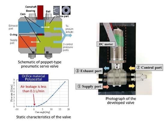
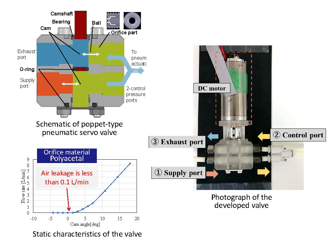
2. Developed Valve
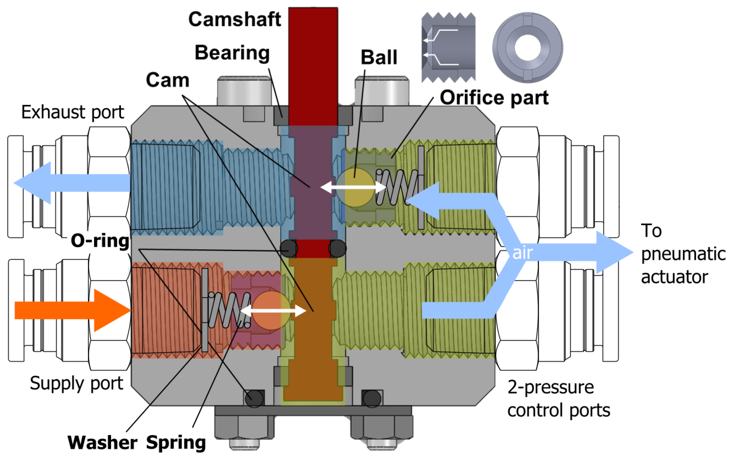
2.1. Valve Structure
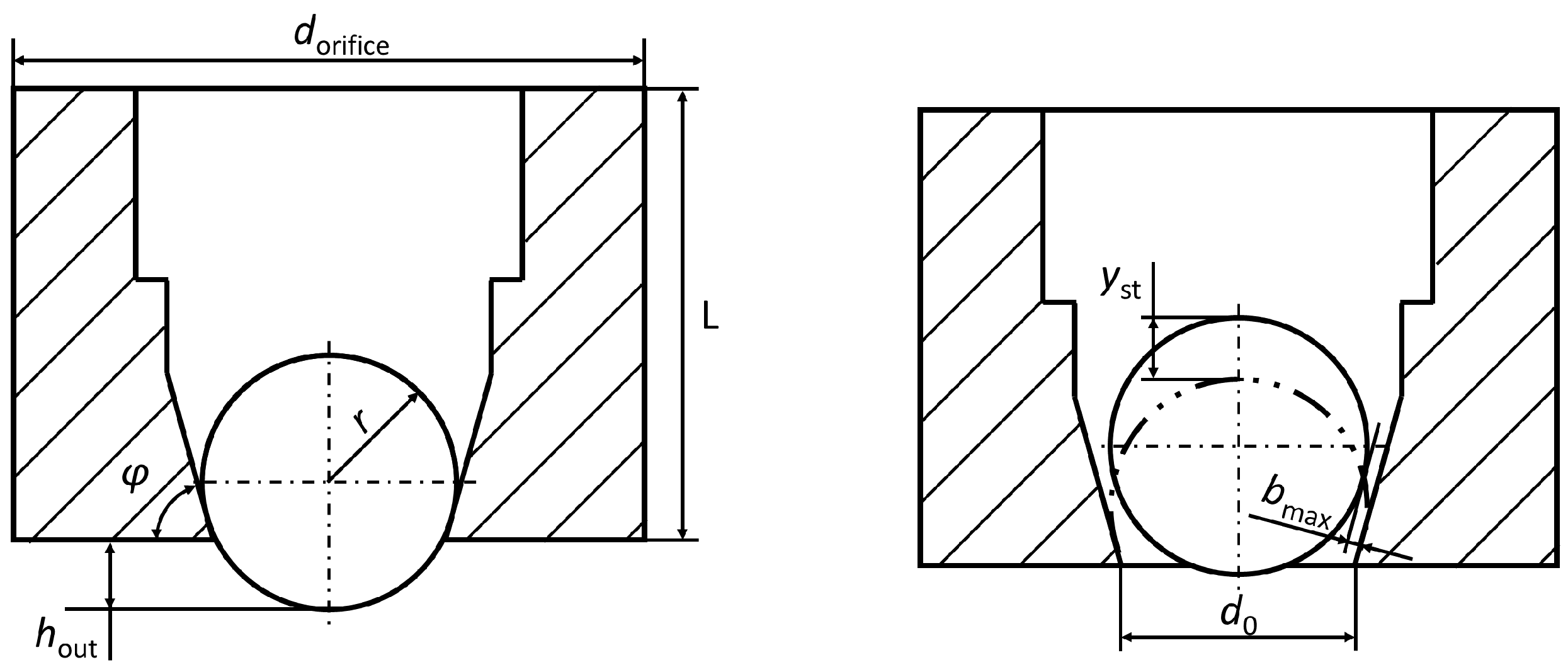
2.2. Orifice Design
2.3. Selection of Orifice Material
2.4. Cam Design
2.5. Motor Selection
3. Valve Characteristics
3.1. Static Characteristics
3.2. Dynamic Characteristics
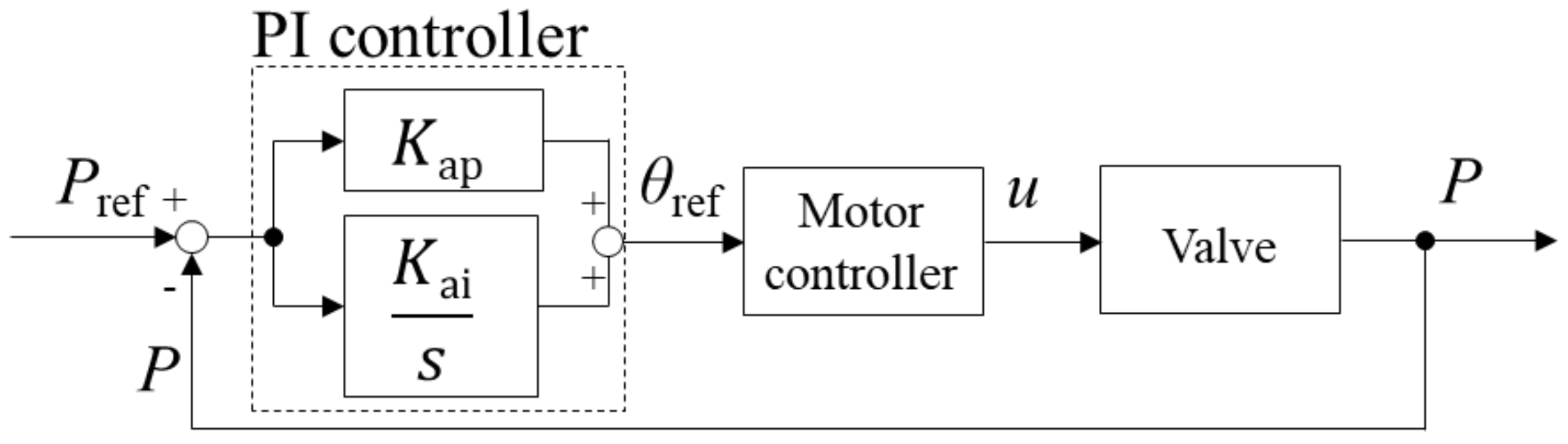
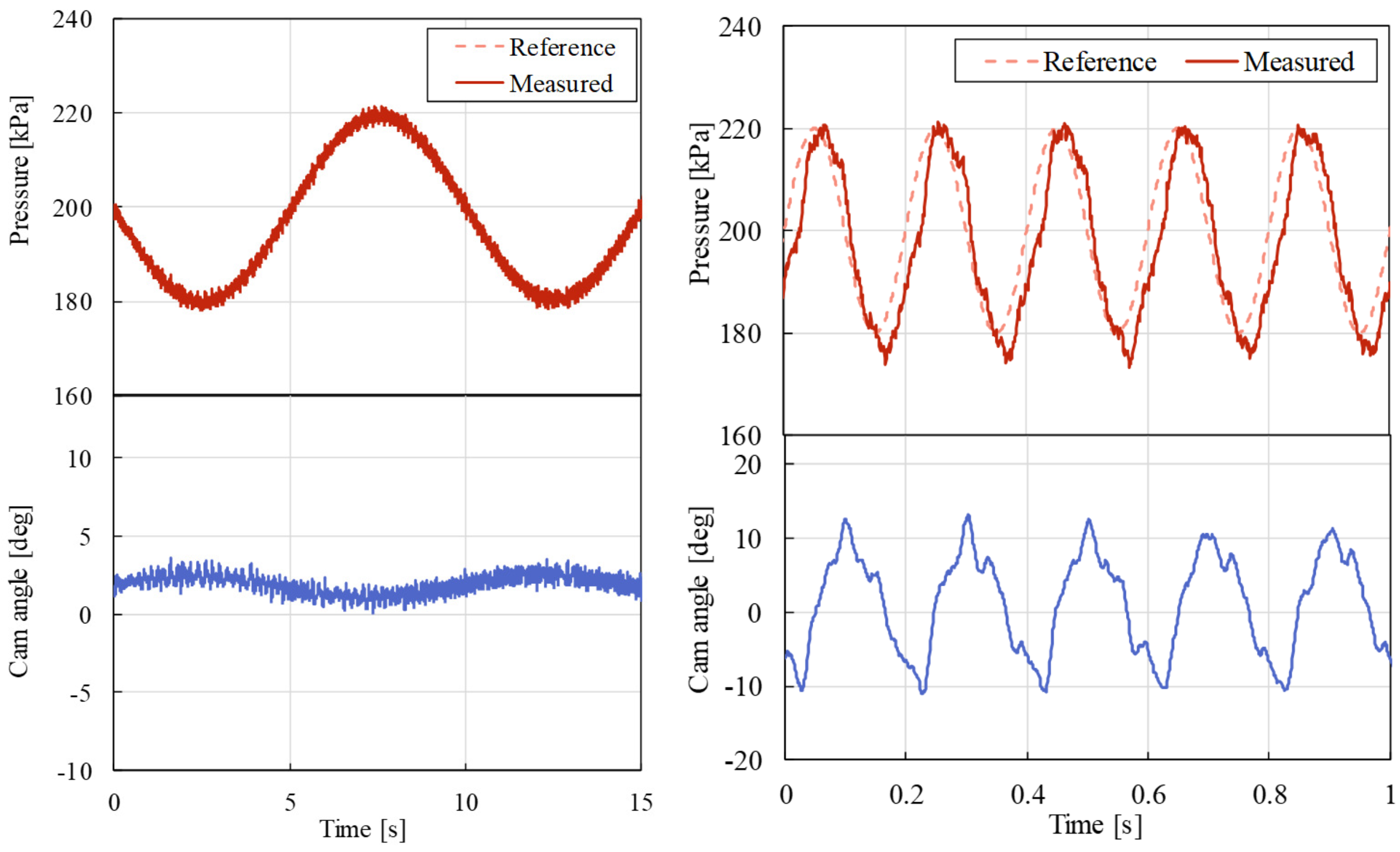
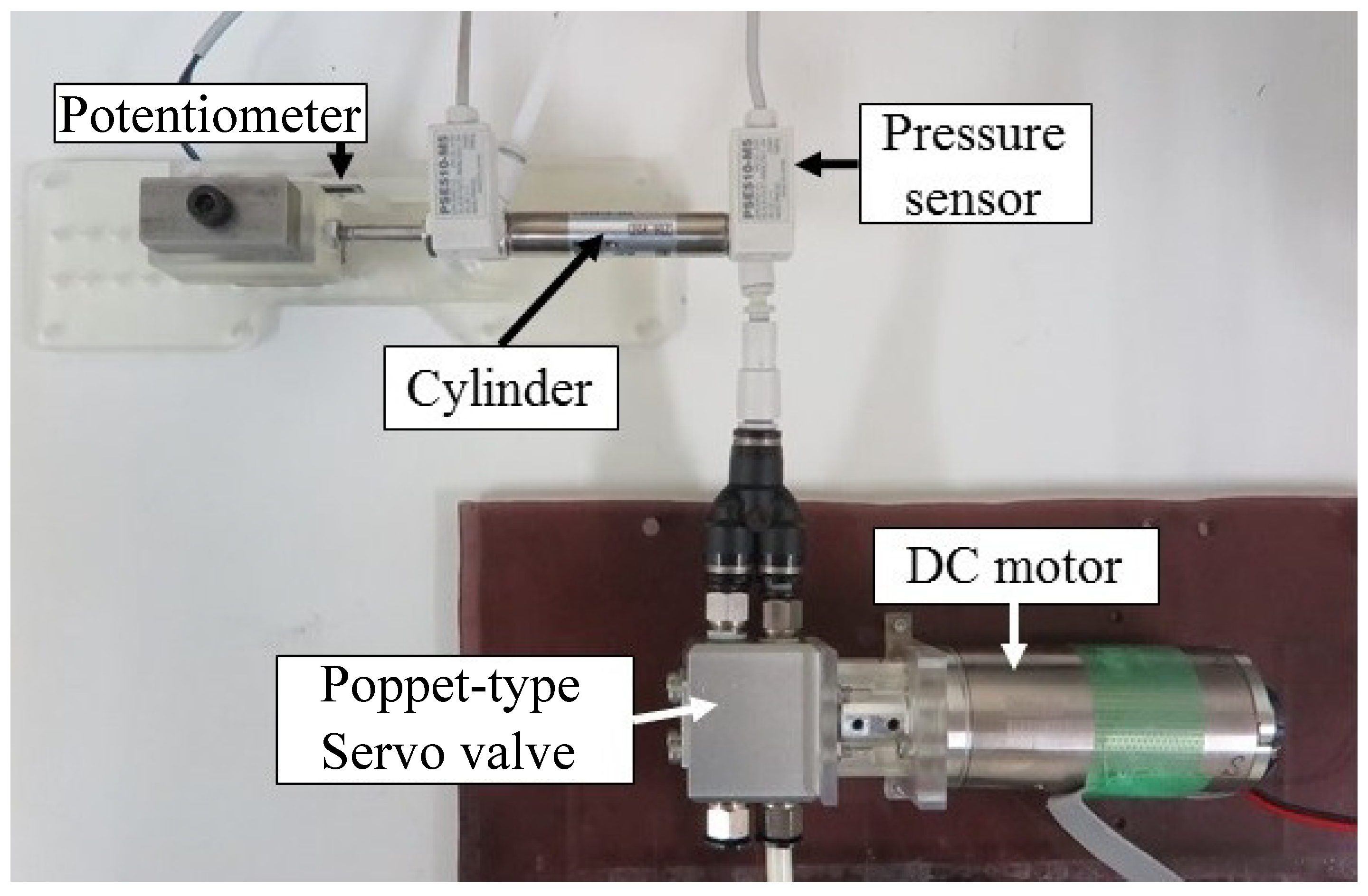
4. Position Control of Pneumatic Cylinder Using the Developed Valve
5. Conclusions
Author Contributions
Funding
Conflicts of Interest
References
- Krivts, I.L. Optimization of performance characteristics of electro pneumatic two-stage servo valve. J. Dyn. Syst. Meas. Control 2004, 126, 416–420. [Google Scholar] [CrossRef]
- Belforte, G.; Mauro, S.; Mattiazo, G. A method for increasing the dynamics performance of pneumatic servo systems with digital valves. Mechatronics 2004, 14, 1105–1120. [Google Scholar] [CrossRef]
- Miyajima, T.; Fujita, T.; Sakaki, K.; Kawashima, K.; Kagawa, T. Development of a digital control system for high-performance pneumatic servo valve. Precis. Eng. 2007, 31, 156–161. [Google Scholar] [CrossRef]
- Li, J.; Choi, J.; Kawashima, K.; Fujita, T.; Kagawa, T. Integrated control design of pneumatic servo table considering the dynamics of pipelines and servo valve. Int. J. Autom. Technol. 2011, 5, 485–492. [Google Scholar] [CrossRef]
- Kawashima, K.; Youn, C.; Kagawa, T. Development of a Nozzle-Flapper Type Servo Valve Using a Slit Structure. J. Fluid Eng. 2007, 129, 573–578. [Google Scholar] [CrossRef]
- Kagawa, T. Heat Transfer Effects on the Frequency Response of a Pneumatic Nozzle Flapper. J. Dyn. Syst. Meas. Control 1985, 107, 332–336. [Google Scholar] [CrossRef]
- Kamali, M.; Jazayeri, S.A.; Najafi, F.; Kawashima, K.; Kagawa, T. Integrated nozzle-flapper valve with piezoelectric actuator and isothermal chamber: A feedback linearization multi control device. J. Mech. Sci. Technol. 2016, 30, 2293–2301. [Google Scholar] [CrossRef]
- Liu, S.; Bobrow, J.E. An analysis of a pneumatic servo system and its application to a computer-controlled robot. J. Dyn. Syst. Meas. Control 1988, 110, 228–235. [Google Scholar] [CrossRef]
- Pu, J.; Weston, R.H. A new generation of pneumatic servo for industrial robot. Robotica 1989, 7, 17–24. [Google Scholar] [CrossRef]
- Haraguchi, D.; Kanno, T.; Tadano, K.; Kawashima, K. A Pneumatically-Driven Surgical Manipulator with a Flexible Distal Joint Capable of Force Sensing. IEEE/ASME Trans. Mechatron. 2015, 20, 2950–2961. [Google Scholar] [CrossRef]
- Uehara, S.; Hirai, S. Unconstrained Vibrational Pneumatic Valves for Miniaturized Proportional Control Devices. In Proceedings of the 9th International Conference Mechatronics Technology, Kuala Lumpur, Malaysia, 5–8 December 2005. [Google Scholar]
- Akagi, T.; Dohta, S.; Katayama, S. Development of Small-Sized Flexible Pneumatic Valve Using Vibration Motor and Its Application for Wearable Actuator. In Proceedings of the 15th International Conference Mechatronics Machine vision Practice, Auckland, New Zealand, 2–4 December 2008; pp. 441–446. [Google Scholar]
- Nasir, A.; Akagi, T.; Dohta, S.; Ono, A. Analysis of Low-cost Wearable Servo Valve Using Buckled Tubes for Optimal Arrangement of Tubes. In Proceedings of the IEEE International Conference on Advaced Intelligent Mechatronics, Busan, Korea, 7–11 July 2015; pp. 830–835. [Google Scholar]
- Morisaki, D.; Kanno, T.; Kawashima, K. Development of a Pinch-type Servo Valve Embedded in a Pneumatic Artificial Rubber Muscle. In Proceedings of the IEEE/SICE International Symposium on System Integration, Taipei, Taiwan, 11–14 December 2017. [Google Scholar]
- Carneiro, J.F.; de Almeida, F.G. Using two servovalves to improve pneumatic force control in industrial cylinders. Int. J. Adv. Manuf. Technol. 2013, 66, 283–301. [Google Scholar] [CrossRef]
- Kawashima, K.; Arai, T.; Tadano, K.; Fujita, T.; Kagawa, T. Development of Coarse/Fine Dual Stages using Pneumatically Driven Bellows Actuator and Cylinder with Air Bearings. Precis. Eng. 2010, 34, 526–533. [Google Scholar] [CrossRef]
- Kawashima, K.; Ishii, Y.; Funaki, T.; Kagawa, T. Determination of Flow Rate Characteristics of Pneumatic Solenoid Valves Using an Isothermal Chamber. J. Fluid Eng. 2004, 126, 273–279. [Google Scholar] [CrossRef]
- Andersen, B.W. The Analysis and Design of Pneumatic Systems; Krieger Publishing Company: Malabar, FL, USA, 2010. [Google Scholar]
- Takosoglu, J.; Laski, P.; Blasiak, S.; Bracha, G.; Pietrala, D.; Zwierzchowski, J.; Nowakowski, L. Determination of flow-rate characteristics and parameters of piezo pilot valves. EPJ Web Conf. 2017, 143, 02126. [Google Scholar] [CrossRef]


| Parameters | Value |
|---|---|
| Radius r | 2 mm |
| Orifice angle | 75 deg |
| Orifice diameter | 3.6 mm |
| Materials | Value |
|---|---|
| Aluminum r | 18.8 L/min |
| Polypropylene | 1.0 L/min |
| Polyacetal. | 0.1 L/min |
| 4.0 V/kPa | |
| 0.25 V/kPa s |
| 38 kPa/mm | |
| 1.5 kPa/mm s | |
| 0 kPa s/mm | |
| 0.25 V/kPa | |
| 0.12 V/kPa s |
© 2018 by the authors. Licensee MDPI, Basel, Switzerland. This article is an open access article distributed under the terms and conditions of the Creative Commons Attribution (CC BY) license (http://creativecommons.org/licenses/by/4.0/).
Share and Cite
Kanno, T.; Hasegawa, T.; Miyazaki, T.; Yamamoto, N.; Haraguchi, D.; Kawashima, K. Development of a Poppet-Type Pneumatic Servo Valve. Appl. Sci. 2018, 8, 2094. https://doi.org/10.3390/app8112094
Kanno T, Hasegawa T, Miyazaki T, Yamamoto N, Haraguchi D, Kawashima K. Development of a Poppet-Type Pneumatic Servo Valve. Applied Sciences. 2018; 8(11):2094. https://doi.org/10.3390/app8112094
Chicago/Turabian StyleKanno, Takahiro, Takashi Hasegawa, Tetsuro Miyazaki, Nobuyuki Yamamoto, Daisuke Haraguchi, and Kenji Kawashima. 2018. "Development of a Poppet-Type Pneumatic Servo Valve" Applied Sciences 8, no. 11: 2094. https://doi.org/10.3390/app8112094
APA StyleKanno, T., Hasegawa, T., Miyazaki, T., Yamamoto, N., Haraguchi, D., & Kawashima, K. (2018). Development of a Poppet-Type Pneumatic Servo Valve. Applied Sciences, 8(11), 2094. https://doi.org/10.3390/app8112094