400GbE Technology Demonstration Using CFP8 Pluggable Modules


Abstract
:1. Introduction
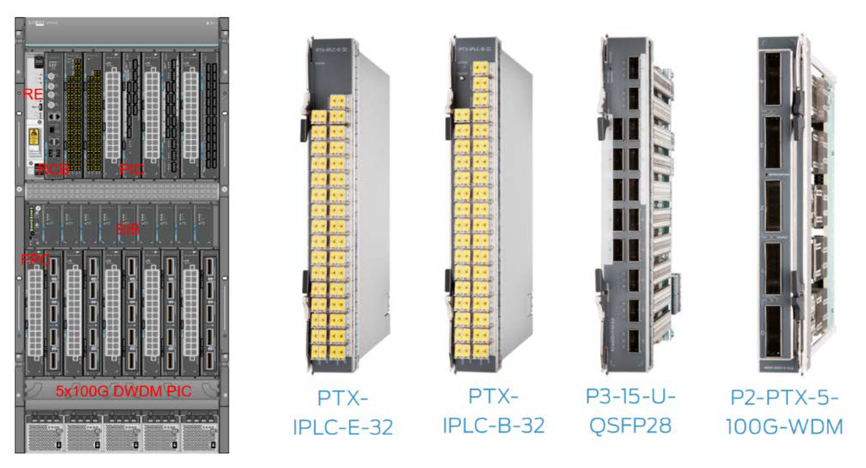
2. 400GE Pluggable Module and Host Card
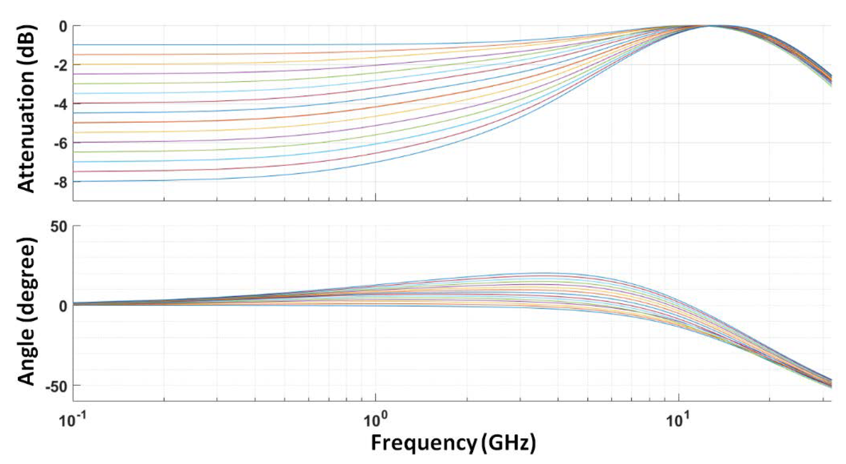
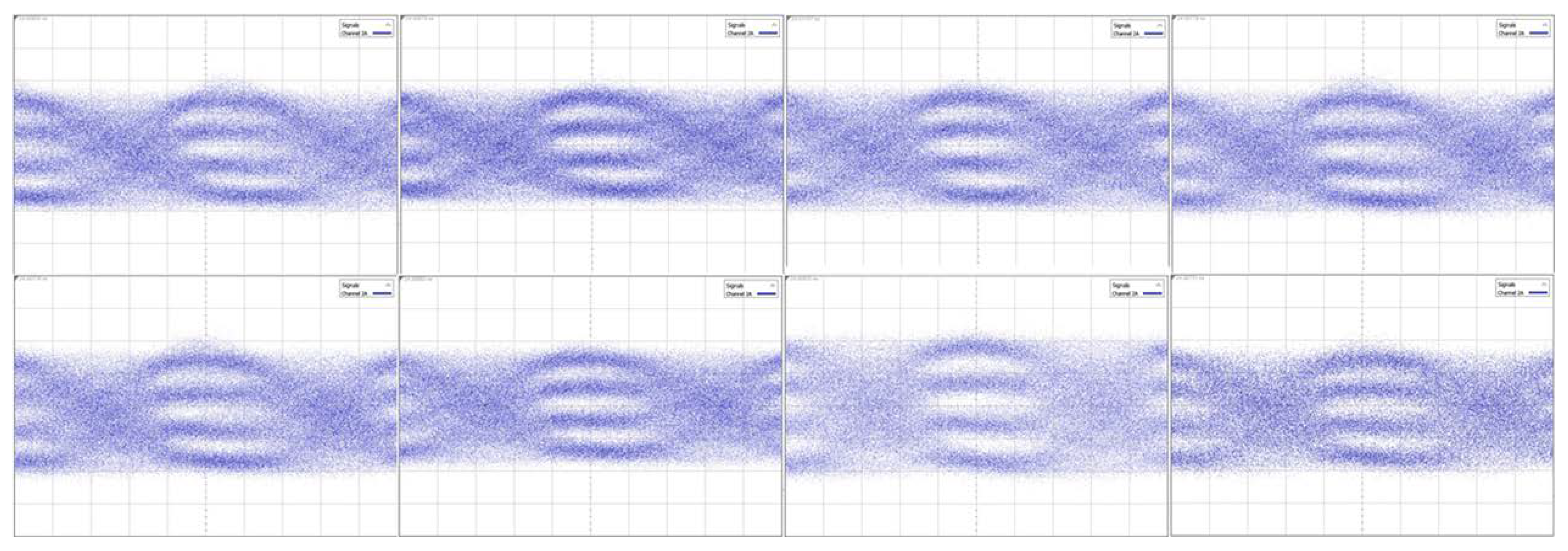
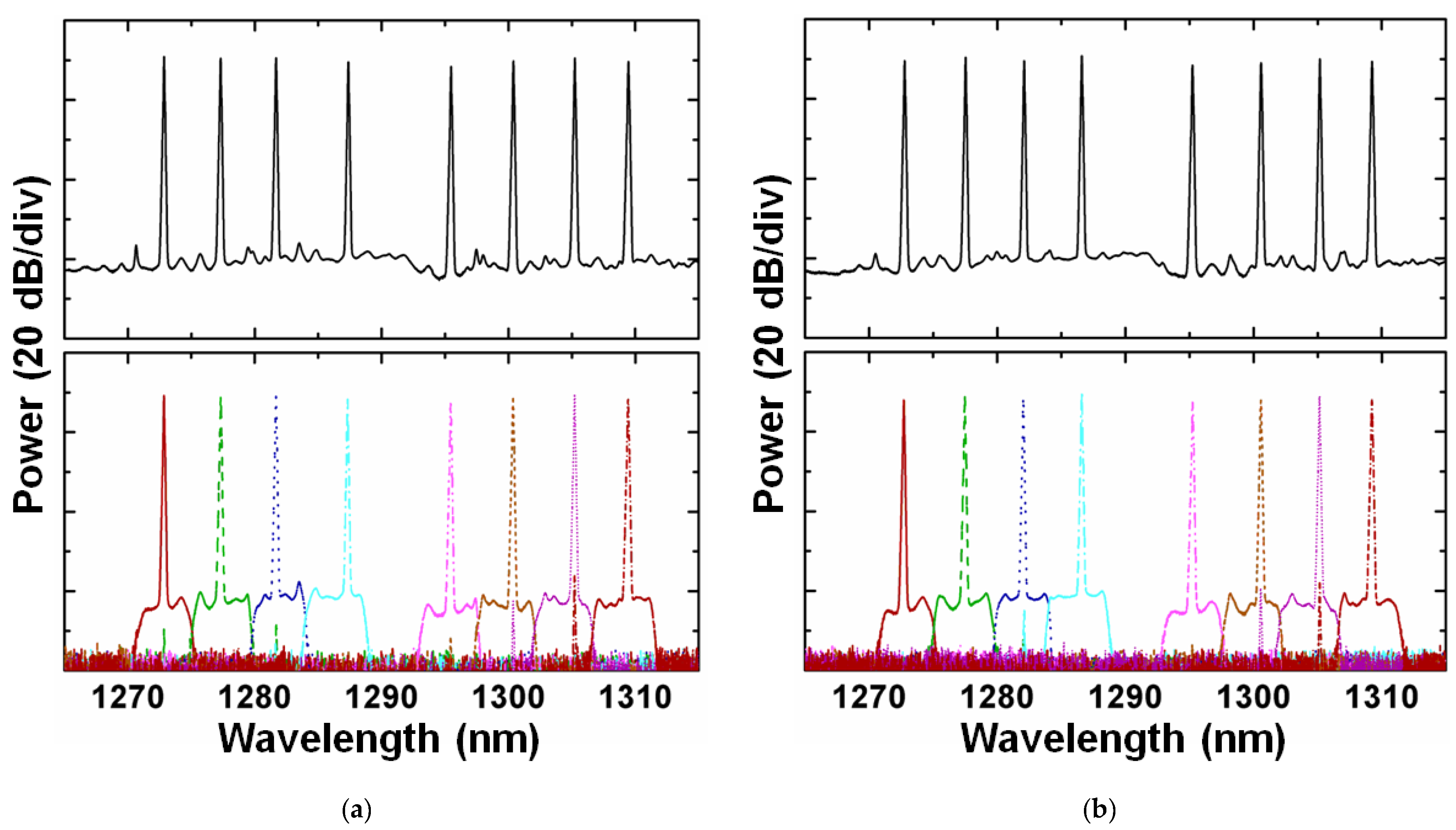
3. Transmitter Performance
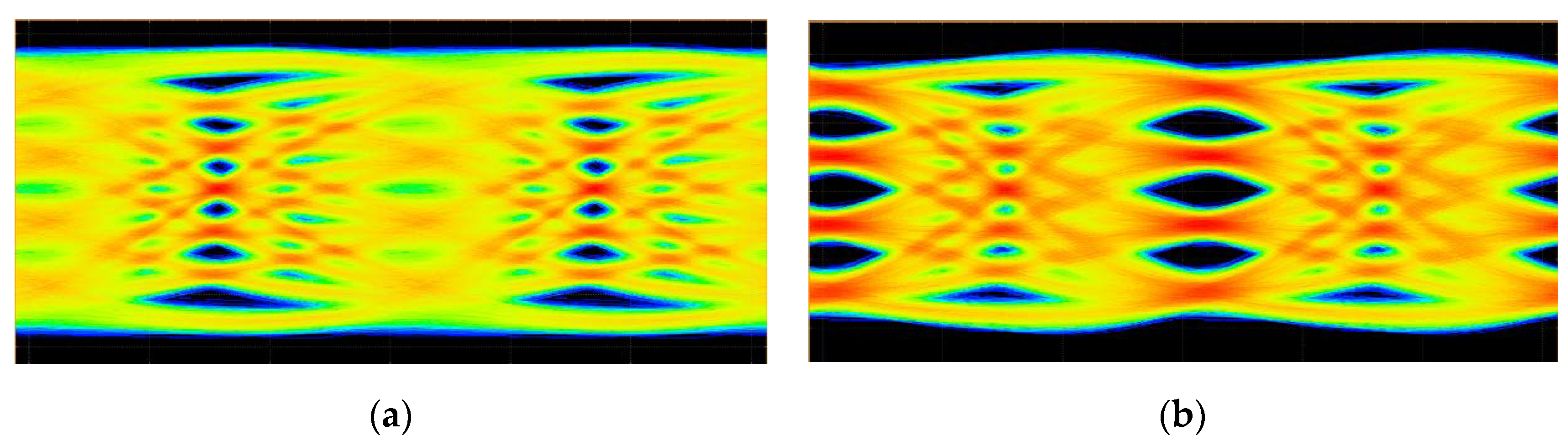
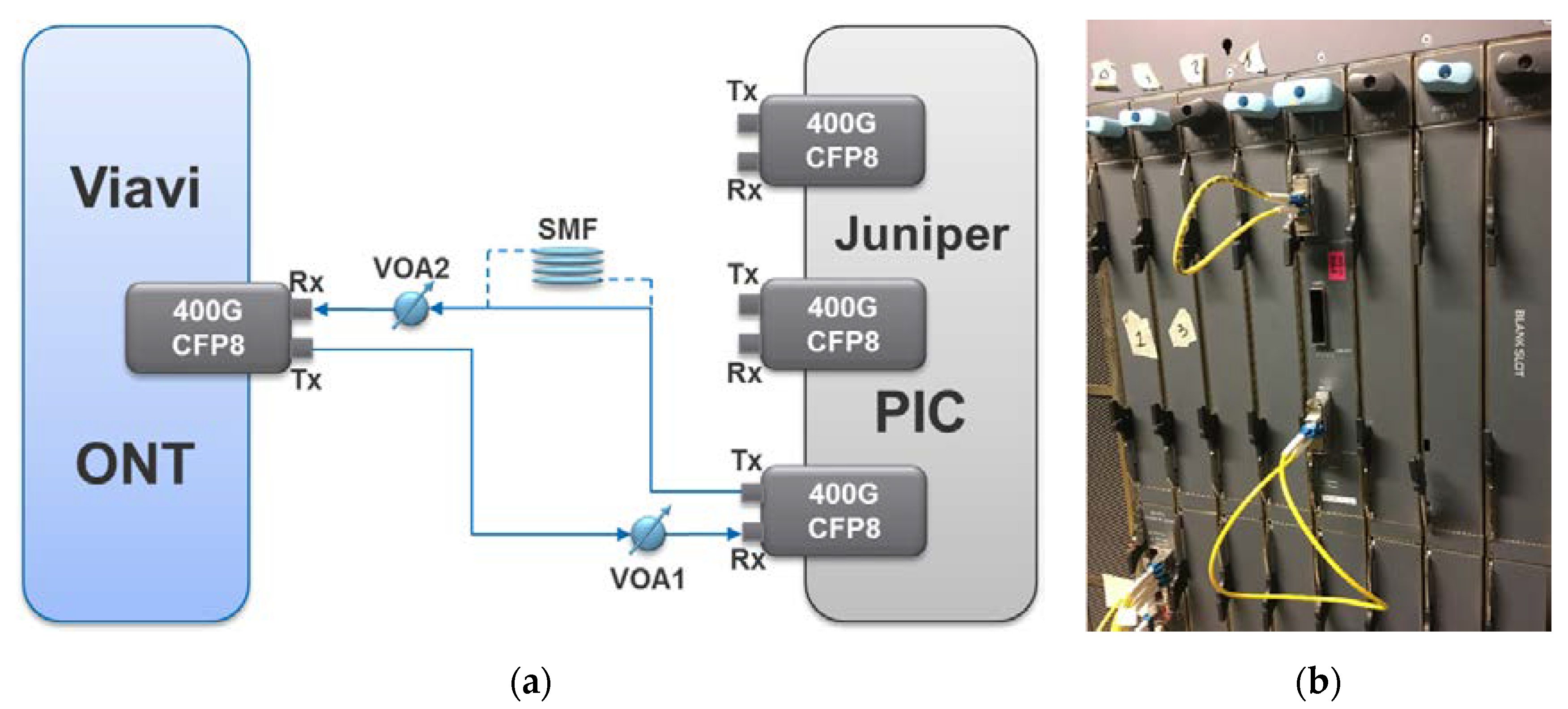
4. Link Performance
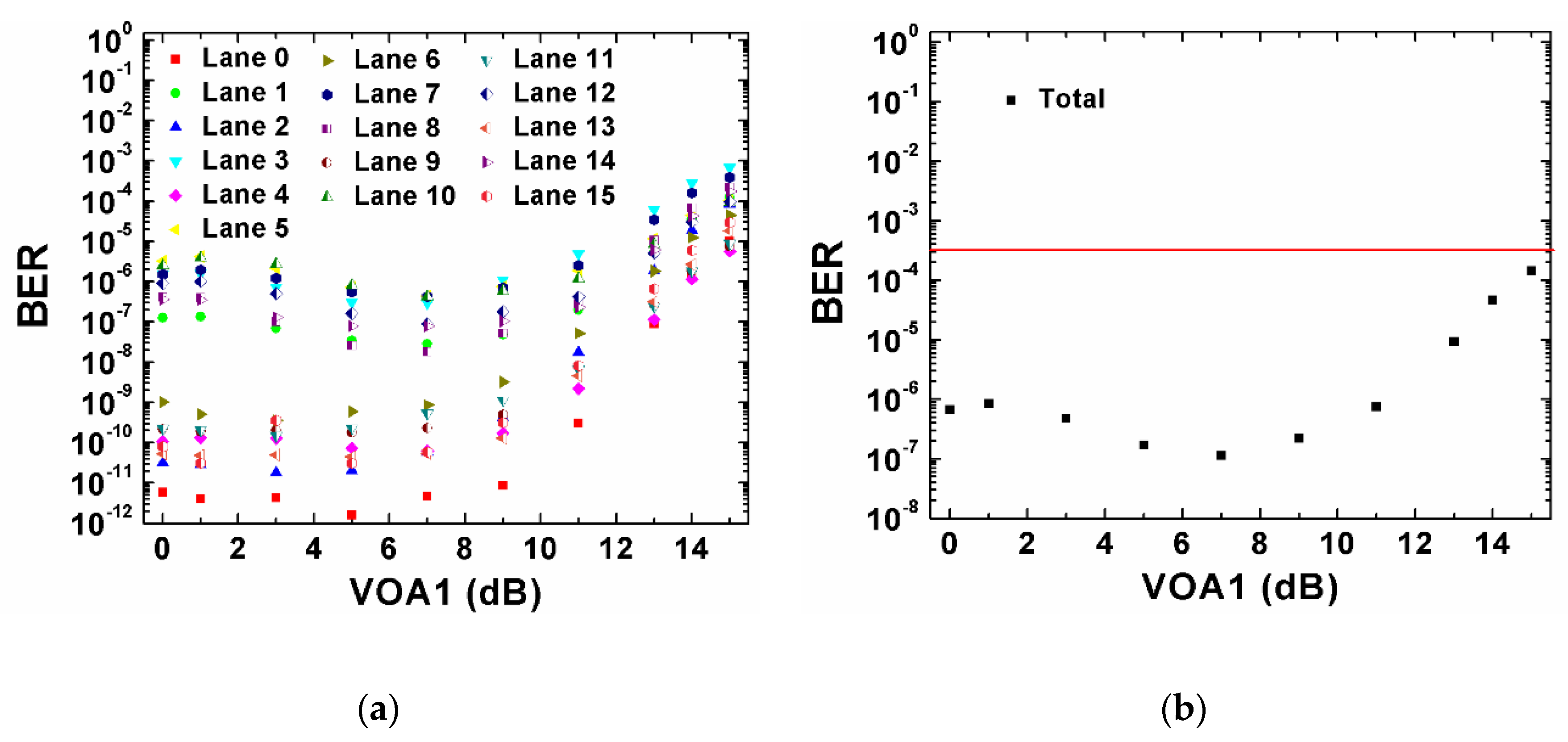
4.1. Back-to-Back Performance
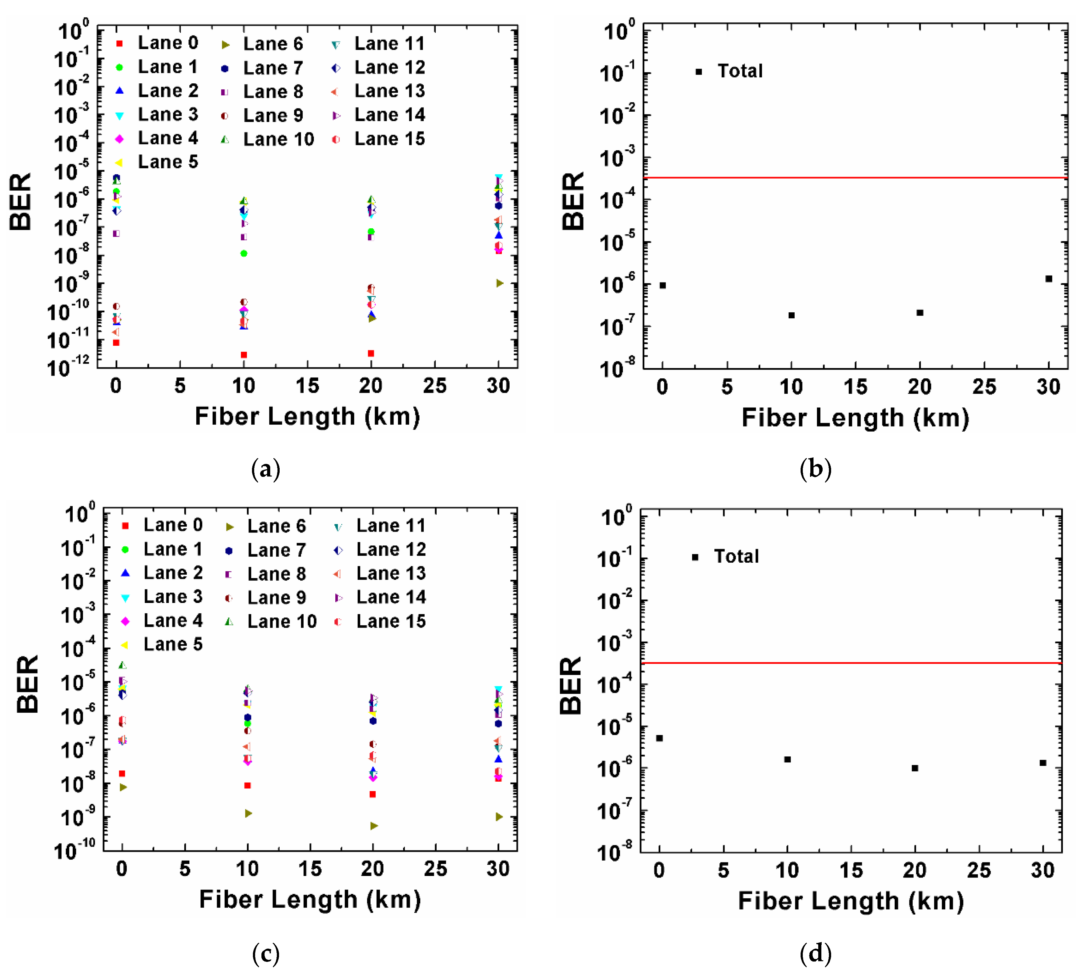
4.2. Fiber Transmission
5. Conclusions
Author Contributions
Funding
Acknowledgments
Conflicts of Interest
References
- Kaminow, I.; Li, T.; Willner, A.E. Optical Fiber Telecommunications, 6th ed.; Academic Press: San Diego, CA, USA, 2013; ISBN 9780123969606. [Google Scholar]
- Bozinovic, N.; Yue, Y.; Ren, Y.; Tur, M.; Kristensen, P.; Huang, H.; Willner, A.; Ramachandran, S. Terabit-scale orbital angular momentum mode division multiplexing in fibers. Science 2013, 340, 1545–1548. [Google Scholar] [CrossRef] [PubMed]
- Winzer, P.J. Making spatial multiplexing a reality. Nat. Photonics 2014, 8, 345–348. [Google Scholar] [CrossRef]
- IEEE P802.3bs 400 Gb/s Ethernet Task Force. Available online: www.ieee802.org/3/bs/ (accessed on 1 September 2018).
- Rokkas, T.; Neokosmidis, I.; Tomkos, I. Cost and Power Consumption Comparison of 400 Gbps Intra-Datacenter Transceiver Modules. In Proceedings of the 2018 International Conference on Transparent Optical Networks (ICTON), Bucharest, Romania, 1–5 July 2018. [Google Scholar]
- Nelson, L.E.; Zhang, G.; Padi, N.; Skolnick, C.; Benson, K.; Kaylor, T.; Iwamatsu, S.; Inderst, R.; Marques, F.; Fonseca, D.; et al. SDN-Controlled 400GbE end-to-end service using a CFP8 client over a deployed, commercial flexible ROADM system. In Proceedings of the 2017 Optical Fiber Communications Conference and Exposition (OFC), Los Angeles, CA, USA, 19–23 March 2017. [Google Scholar]
- Birk, M.; Nelson, L.E.; Zhang, G.; Cole, C.; Yu, C.; Akashi, M.; Hiramoto, K.; Fu, X.; Brooks, P.; Schubert, A.; et al. First 400GBASE-LR8 interoperability using CFP8 modules. In Proceedings of the 2017 Optical Fiber Communications Conference and Exposition (OFC), Los Angeles, CA, USA, 19–23 March 2017. [Google Scholar]
- Nelson, L.E. Advances in 400 Gigabit Ethernet Field Trials. In Proceedings of the 2018 Optical Fiber Communications Conference and Exposition (OFC), San Diego, CA, USA, 11–15 March 2018. [Google Scholar]
- CFP-MSA. Available online: http://www.cfp-msa.org/ (accessed on 1 September 2018).
- SFF Committee. Available online: http://www.sffcommittee.com/ie/ (accessed on 1 September 2018).
- OSFP. Available online: http://osfpmsa.org/index.html (accessed on 1 September 2018).
- QSFP-DD. Available online: http://www.qsfp-dd.com/ (accessed on 1 September 2018).
- OIF: Optical Internetworking Forum. Available online: http://www.oiforum.com/ (accessed on 1 September 2018).
- Cole, C. Beyond 100G client optics. IEEE Commun. Mag. 2012, 50, s58–s66. [Google Scholar] [CrossRef]
- Yue, Y.; Wang, Q.; Maki, J.J.; Zhang, B.; O’Neil, J.; Vovan, A.; Anderson, J. Latest Industry Trend in Pluggable Optics. In Proceedings of the 2017 International Conference on Optical Communications and Networks (ICOCN), Wuzhen, China, 7–10 August 2017. [Google Scholar]
- Isono, H. Latest standardization trends for client and networking optical transceivers and its future directions. In Proceedings of the 2018 optoelectronics, photonic materials and devices conference (SPIE OPTO), San Francisco, CA, USA, 27 January–1 February 2018. [Google Scholar]
- Chagnon, M.; Lessard, S.; Plant, D.V. 336 Gb/s in Direct Detection below KP4 FEC Threshold for Intra Data Center Applications. IEEE Photonics Technol. Lett. 2016, 28, 2233–2236. [Google Scholar] [CrossRef]


© 2018 by the authors. Licensee MDPI, Basel, Switzerland. This article is an open access article distributed under the terms and conditions of the Creative Commons Attribution (CC BY) license (http://creativecommons.org/licenses/by/4.0/).
Share and Cite
Yue, Y.; Wang, Q.; Yao, J.; O’Neil, J.; Pudvay, D.; Anderson, J. 400GbE Technology Demonstration Using CFP8 Pluggable Modules. Appl. Sci. 2018, 8, 2055. https://doi.org/10.3390/app8112055
Yue Y, Wang Q, Yao J, O’Neil J, Pudvay D, Anderson J. 400GbE Technology Demonstration Using CFP8 Pluggable Modules. Applied Sciences. 2018; 8(11):2055. https://doi.org/10.3390/app8112055
Chicago/Turabian StyleYue, Yang, Qiang Wang, Jian Yao, Jason O’Neil, Daniel Pudvay, and Jon Anderson. 2018. "400GbE Technology Demonstration Using CFP8 Pluggable Modules" Applied Sciences 8, no. 11: 2055. https://doi.org/10.3390/app8112055
APA StyleYue, Y., Wang, Q., Yao, J., O’Neil, J., Pudvay, D., & Anderson, J. (2018). 400GbE Technology Demonstration Using CFP8 Pluggable Modules. Applied Sciences, 8(11), 2055. https://doi.org/10.3390/app8112055